
| “This site contains affiliate links for which OEMDTC may be compensated” |
CR211 – Rear Brake Hoses Replacement
XDiavel Model Year 2016-2020 (USA-CAN only) Safety Recall Campaign SRV-RCL-21-004
| Date: | May 27, 2021 |
| To: | Dealer Principal, General Manager, Service Manager, North American Dealer Network |
| From: | Richard Kenton, Technical Director Eric Bradley, Technical Training and Publications Manager |
Dear Dealers,
Ongoing product quality testing and field reports have identified a potential for the rear brake application to soften over time as a consequence of use. To correct in cases of this occurrence, new rear brake hoses (ABS control unit to rear brake master cylinder – green – and ABS control unit to rear brake caliper – yellow) will be installed to replace the rear brake hoses for the above listed model.
NOTE
All XDiavel model versions currently produced and being shipped by DMH to all destinations have already been equipped with these new brake hoses
Application
You can find the precise list of VIN numbers involved in CR211 on the DCS, in sections:
| VIN HISTORY | It is possible to search by individual frame number. | |
| CAMPAIGNS | It is possible to search for all the frame numbers that you received from Ducati Motor Holding. |
Customer Impact
All motorcycles in your inventory (to be registered or already registered) and to be delivered to final Customers must be updated during pre-delivery operations and always before delivery to the final Customer. All motorcycles already delivered to final Customers must undergo this inspection as soon as they come to your workshop.
Parts Distribution
The following components required to carry out the upgrade under this Safety Recall Campaign must be ordered for each affected frame number.
- 61911361A: ABS control unit / rear brake master cylinder hose
- 61911341A: ABS control unit / rear brake caliper hose
- 85250241A: Copper washers (8pcs)
The required self-locking ties (small (7 pcs) and large (3 pcs)) are easy to find consumables and should be sourced locally.
Warranty Reimbursement Rules
Reimbursement for work associated with this Safety Recall Campaign will be made through the regular warranty claim procedure using the “Vehicle History” section of the DCS.
The warranty claim is pre-filled and is identified as CR211.
The dealer shall be reimbursed for the parts listed for the operation; copper washers (8) part no. 85250241A, ABS control unit / rear brake master cylinder hose Part no.61911361A, ABS control unit / rear brake caliper hose Part no.61911341A), the consumable ties and DOT 4 brake fluid; and labor for 2h:54min (29 labor units) that includes the time necessary for:
- Vehicle reception
- Rear brake hose removal (ABS control unit / brake master cylinder and ABS control unit / brake caliper)
- Installation of new rear brake hose assembly (ABS control unit / brake master cylinder and ABS control unit / brake caliper)
- Filling and bleeding procedure of the rear brake system
- Soft cleaning of the vehicle
| Table of Contents | Page |
| Introduction | 1 |
| Application | 2 |
| Customer Impact | 2 |
| Parts Distribution | 2 |
| Warranty Reimbursement Rules | 2 |
| Spare Parts | 4 |
| Service Solution | 4 |
| Part 1: Vehicle Preparation | 4 |
| Part 2: Rear Brake Hose Removal | 14 |
| Part 3: Rear Brake Hose Installation – Master Cyl. to ABS control | 16 |
| Part 4: Rear Brake Hose Installation – ABS Control to Rear Caliper | 18 |
| Part 5: Rear Brake System Filling and Bleeding | 23 |
| Part 6: Vehicle Refitting | 24 |
| Additional Requirements and Notes | 33 |
| Customer Letter Example | 34 |
Spare Parts
| Part No. | Description | Picture |
| 61911361A | ABS control unit / rear brake master cylinder hose | |
| 61911341A | ABS control unit / rear brake caliper hose | |
| 85250241A | Copper washers (8pcs) | (x8) |
Service Solution
WARNING To ensure the correct execution of the operation within the provided labor time to carry out the updates, it is necessary to follow the sequence indicated in the following instructions
Part 1: Vehicle Preparation
1. Position the vehicle on the rear paddock stand
2. Drain all brake fluid contained inside the rear brake system
WARNING
Brake fluid may damage the paint or parts of the motorcycle. Wash the affected area with plenty of water in case of accidental contact. Damage due to brake fluid spillage is not a warrantable defect and is the responsibility of the repairing dealer to correct
3. Remove the seat
4. Remove the M6x20 screw (1) with washer (2) retaining fuel tank
5. Slightly lift the fuel tank, disconnect the fuel supply hose (3), the ground cable (4) and the fuel pump connector (5)
NOTE
To disconnect the fuel supply hose (3) press on the flange in point (6) and at the same time tighten the outer ring (7) in the indicated points
6. Disconnect the fuel level sensor connector (8)
7. Lift the fuel tank by pulling out the 2 pins (9) from the relevant supports (X)
8. Pull out the drain hose (10) and the canister filter breather tube (11) from the fuel tank
9. Remove the 2 M6x22 screws (12) with the relevant spacers (13) fastening RH cover (14) and LH cover (15) of the engine
10. Remove the filter cover (16) by unscrewing the 4 self-tapping screws (17)
11. Disconnect the air temperature sensor connector (18)
12. Working on vehicle LH side:
13. Working on vehicle LH side:
13.1 Remove the 2 M6x10 screws (20) securing the connector support
13.2 Remove the 2 M6x25 screws (21) securing ignition coil (22) and disconnect the relevant connector (23)
13.3 Disconnect secondary air (AIS) connector (24)
13.4 Remove the 2 spring retainers (25) and pull out the horizontal head secondary air pipe (26) and the vertical head secondary air pipe
13.5 Disconnect vertical cylinder ETV (28), injection (29) and horizontal cylinder ETV (30) connectors
13.6 Remove tie (31) and pull out Airbox drain hose (32)
14. Working on vehicle RH side:
14.1 Pull out horizontal cylinder head pressure sensor pipe (33) acting on clamp (34)
14.2 Disconnect horizontal cylinder head pressure sensor connector (35)
14.3 Pull out blow-by hose (36) from the Airbox by loosening tie (37)
15. Working on vehicle LH side, loosen tie (38) positioned on the horizontal cylinder head and tie (39) positioned on the vertical cylinder head
15.1 Remove the Airbox from the vehicle
15.2 Protect the engine with a cloth near the ABS control unit and cover the intake manifolds as shown in the figure to avoid the possible penetration of brake fluid or impurities inside the manifolds.
WARNING
Brake fluid may damage the paint or parts of the motorcycle. Wash the affected area with plenty of water in case of accidental contact. Damage due to brake fluid spillage is not a warrantable defect and is the responsibility of the repairing dealer to correct
16. Remove the rear wheel (See Sec. 7: “Chassis – Rear wheel” of the Workshop Manual)
17. Remove the rear mudguard (See Sec.5: “Fairing installation – Rear and front mudguard” of the Workshop Manual)
18. Before carrying out the removal of: hose (40) connecting the ABS control unit to the rear brake master cylinder, hose (41) connecting the ABS control unit to the rear brake caliper it is necessary to perform the following:
19. Pull out the brake hose (40) from the relevant tabs (42) present on the coolant radiator
20. Pull out the brake hose (41) from cable guide (43)
21. Remove 3 L.39mm button ties (44) joining the brake hose (41) to the speed sensor cable and rear turn indicator cable\
22. Remove 3 small self-locking ties (45) joining the brake hose (41) to the speed sensor cable and rear turn indicator cable
23. Pull out the brake hose (41) from the 2 teeth (46) present on the rear shock absorber reservoir support
24. Remove the 2 hose grommets (47) on swinging arm
25. Remove 4 small self-locking ties (48) joining the brake hose (41), the speed sensor cable and rear turn indicator cable
26. Remove 3 big self-locking ties (49) joining the brake hose (41), the speed sensor cable and rear turn indicator cable
27. Remove the 3 M6x18 screws (50) securing the air conveyor to the horizontal belt cover
NOTE
It is recommended to remove the air conveyor on horizontal belt cover to make the removal and installation operation of the brake hose connecting the ABS control unit to the rear brake master cylinder easier.
Part 2: Rear Brake Hose Removal
1. Working on the ABS control unit, remove the special screw (51) with the 2 copper washers (52) securing brake hose (40) to ABS control unit.
WARNING
Brake fluid may damage the paint or parts of the motorcycle. Wash the affected area with plenty of water in case of accidental contact. Damage due to brake fluid spillage is not a warrantable defect and is the responsibility of the repairing dealer to correct
2. Working on the rear brake master cylinder, remove the special screw (53) with the 2 copper washers (54) securing brake hose (40) to rear brake master cylinder
3. Pull out brake hose (40) starting from the rear brake master cylinder fitting
4. Working on the ABS control unit, remove the special screw (55) with the 2 copper washers (56) securing brake hose (41) to ABS control unit
5. Working on the rear brake caliper, remove the special screw (57) with the 2 copper washers (58) securing brake hose (41) to rear brake caliper
6. Pull out brake hose (41) by first routing the ABS control unit fitting below the rear subframe jointing bracket and then pulling it out starting from the ABS control unit fitting
Part 3: New Rear Brake Hose Installation – Brake hose connecting the ABS control unit to the rear brake master cylinder
1. Take the new brake hose (A) connecting the ABS control unit to the rear brake master cylinder
NOTE
The new brake hose can be identified by the different chamfering that characterizes the end part of the fittings.
2. Insert the ABS control unit fitting of the brake hose (A) between the coolant radiator and the horizontal head cover and route it inside the frame until reaching the ABS control unit, as shown in the figure
3. Route hose (A) between the 2 tabs (42) present on the coolant radiator
4. Position the seal (59) inside hose grommet (60) present on frame
5. Fasten the ABS control unit fitting to the control unit as shown in the figure, using 2 new copper washers (B) and tighten the special screw (51) to 25 Nm ± 5% with certification
6. Fasten the rear brake master cylinder fitting as shown in the figure using 2 new copper washers (C) and tighten the special screw (53) to 25 Nm ± 5% with certification
Part 4: New Rear Brake Hose Installation – Brake hose connecting the ABS control unit to the rear brake caliper
1. Take the new brake hose (D) connecting the ABS control unit to the rear brake caliper.
NOTE
The new brake hose can be recognized by the different chamfering that characterizes the end part of the fittings.
2. Install the brake hose (D) as indicated below:
2.1 Route the ABS control unit fitting below the rear subframe jointing bracket
2.2 Insert the rear brake caliper fitting of the brake hose (D) between the rear subframe and the vertical head exhaust manifold
2.3 Route the brake hose (D) between the footrest holder plate and the swinging arm
3. Fasten the fitting to the ABS control unit as shown in the figure, using 2 new copper washers (E) and tighten the special screw (55) to 25 Nm ± 5% with certification
4. Fasten the rear brake caliper fitting as shown in the figure using 2 new copper washers (F) and tighten the special screw (57) to 25 Nm ± 5% with certification
WARNING
Make sure that brake hose (A) and brake hose (D) fittings are aimed on the ABS control unit as shown in the figure and check also that there are no interferences.
WARNING
Make sure that brake hose (A) and brake hose (D) fittings are respectively aimed on the brake master cylinder and brake caliper as shown in the figure.
5. Fasten the new brake hose (D) connecting the ABS control unit to the rear brake caliper, as shown below:
5.1 Insert brake hose (D) inside the cable guide (43)
5.2 Join the brake hose (D) to the speed sensor cable and the rear turn indicator cable using the 2 L.39mm button ties (44)
5.3 Join the brake hose (D) to the speed sensor cable connector and the rear turn indicator wiring branch using the L.39mm button tie (63)
5.4 Join the brake hose (D) to the speed sensor cable and the rear turn indicator cable using the 3 small self-locking ties (64)
5.5 Insert the brake hose (D) inside the 2 teeth (46) present on the rear shock absorber reservoir support
5.6 Fasten brake hose (D) to the swinging arm using 2 hose grommets (47) and tighten the relevant retaining screws to 8 Nm ± 10%
5.7 Install 4 small self-locking ties (65) joining the brake hose (D), the speed sensor cable and rear turn indicator cable
5.8 Install 3 big self-locking ties (66) joining the brake hose (D), the speed sensor cable and rear turn indicator cable in the following two locations:
- the tie (66A) in correspondence of the clip on the swinging arm;
- the tie (66B) in correspondence of the drive belt protection.
Part 5: Rear Brake System Filling and Bleeding
1. Proceed with the DOT4 fluid filling inside the rear brake system and bleed the system following the procedure indicated in the bulletin SRV-TTB-17-001 valid for the XDiavel model. The video of the bleeding procedure can be watched at the following link: https://youtu.be/hQo1FHPA6–U.

WARNING
Brake fluid may damage the paint or parts of the motorcycle. Wash the affected area with plenty of water in case of accidental contact. Damage due to brake fluid spillage is not a warrantable defect and is the responsibility of the repairing dealer to correct
Part 6: Vehicle Refitting
1. Fit the rear mudguard (See Sec.5: “Fairing installation – Front and rear mudguard”)
2. Refit the rear wheel (See Sec. 7: “Chassis – Rear wheel” of the Workshop Manual)
3. Fit the air conveyor on the horizontal belt cover and tighten the 3 M6x18 screws (50) to 10 Nm ± 10%
4. Remove the adhesive tape from the intake manifolds and apply soapy water on the rubber profile for intake manifold connection at the bottom of the Airbox
5. Install the Airbox on the vehicle making sure that the two intake manifolds are perfectly fitted inside it
6. Working on vehicle LH side, fasten the Airbox using tie (38) at the horizontal cylinder head and tie (39) positioned on the vertical cylinder head and tighten to 5 Nm ± 10%
7. Working on vehicle RH side:
7.1 install horizontal cylinder head pressure sensor pipe (33) and secure it with clamp (34)
7.2 connect horizontal cylinder head pressure sensor connector (35)
7.3 connect Airbox blow-by hose (35) and secure it with tie (36)
8. Working on vehicle LH side
8.1 Connect secondary air (AIS) connector (24)
8.2 Connect the ignition coil connector (23) and fasten the coil (22) to the relevant support by tightening the 2 M6x25 screws (21) to 9 Nm ±10%
8.3 Install the connector support tightening 2 M6x10 screws (20) to 6 Nm ± 10% with LOCTITE 243 applied along the threads
8.4 Install horizontal head secondary air pipe (26) and vertical head secondary air pipe (27) in correspondence of the actuator and fasten them using 2 spring retainers (25)
8.5 Connect vertical cylinder ETV (28), injection (29) and horizontal cylinder ETV (30) connectors
8.6 Connect the Airbox drain hose (32) and secure it with tie (31)
8.7 Install RH cover (14) and LH cover (15) with relevant spacers (13) tightening the 2 M6x22 screws (12) to 1 Nm ± 10%
8.8 Connect the air temperature sensor connector (18)
8.9 Fit the filter cover (16) and tighten the 4 self-tapping screws (17) to 3 Nm ± 10%
NOTE
Before carrying on with the tightening, start the self-tapping screws (17) taking care to start them in the original thread already present.
9. Install the coolant filling plug support and tighten the retaining self-tapping screw (19) to 3 Nm ± 10%
NOTE
Before carrying on with the tightening, start the self-tapping screw (19) taking care to start it in the original thread already present.
10. Install the fuel tank by inserting the 2 pins (9) in the relevant supports (X)
11. Connect the drain hose (10) and the breather tube of the canister filter (11)
12. Connect the fuel level sensor connector (8)
13. Connect the fuel supply hose (3), the ground cable (4) and the fuel pump connector (5)
14. Fasten the fuel tank and tighten the M6x20 screw (1) with the relevant washer (2) to 10 Nm ± 10%
15. Start the engine and keep it at idle until reaching the fan activation condition
16. Connect the DDS 2.0 diagnosis instrument and run a Global Scan
17. Mount the seat
18. Measure height (A1) between rear brake lever lower end and load-bearing surface; brake lever must be in rest position (upper limit stop)
19. Slowly position the 8 kg weight onto rear brake lever; then measure height (B1) between rear brake lever lower end and load-bearing surface
- Note the difference between the measured heights (A1) and (B1)
Rear brake lever stroke 1 = (A1) – (B1)
21. Road test the vehicle on the road at a speed of about 30 mph/ 50 Kph and, by operating only the rear brake, brake until the ABS is engaged at least 10 times
22. Measure again the rear brake lever stroke as referred to under Part 6, step 18
WARNING
The measurement of the rear brake lever stroke required in point (22) must be taken with the same temperature conditions of point (18). Therefore, if the measurement was taken with cold engine, it will be necessary to wait for 2 hours before proceeding.
- Note the difference between the measured heights (A2) and (B2)
Rear brake lever stroke 2 = (A2) – (B2)
24. Compare the 2 stroke values of the rear brake lever
25. If a stroke increase of the rear brake lever is detected, repeat the whole bleed procedure from Part 5,
26. Once the new bleeding procedure is completed, check that the stroke of the rear brake lever has not increased
27. Perform a soft cleaning of the vehicle before delivering it to the Customer
Campaign Authorization
Ducati North America, Inc. will mail a notification letter to all known owners. If a customer does not present this notification letter, it is important that you confirm the eligibility for recall status on the DCS before you commence work. Reimbursement requests for duplicate recall campaign repairs will not be accepted.
Dealer Obligation
This program is designed to complete the necessary repairs and to achieve owner satisfaction. Therefore, we ask that you to take prompt and courteous action in accordance with these directives. Please provide a copy of this communication to every person in your dealership who has recall-related responsibilities. Please direct any questions or concerns to your Service Area Manager.
Thank you for your cooperation.
Service Department Ducati North America, Inc.
For questions on this Safety Recall Campaign, please contact your Service Area Manager.
IMPORTANT SAFETY RECALL
This notice applies to your vehicle: VIN XXXXXXXXXXXXXXXXX NHTSA Recall No. 21V-XXX
May 27, 2021
Customer Name
Customer Address
City, St, Zip Code
Subject:
Ducati Motorcycle: XDiavel MY 2016-2020 all model versions (USA and CAN only)
NHTSA Campaign I.D. Number: 21V-XXX
Dealer Bulletin: SRV-RCL-21-004
Dear Ducati Owner,
This notice is sent to you in accordance with the requirements of the U.S. National Traffic and Motor Vehicle Safety Act. Ducati Motor Holding S.P.A. has decided that a defect which relates to motor vehicle safety exists in certain XDiavel MY 2016-2020 all versions (USA and CAN only). Our records indicate that you are the owner of a Ducati motorcycle affected by this safety recall campaign. Please take the time to read this letter and help us take the appropriate steps to ensure that your vehicle is operating properly.
What is wrong?
It has been determined that due to brake system architecture, there is a potential for greater susceptibility for air permeation through the rear brake hoses into the rear brake system, reducing rear brake effectiveness. If this issue develops during normal use, it develops gradually, providing sufficient warning to the operator that rear braking performance may be degrading. If this issue develops after long periods of time without using the motorcycle, the rider during the pre-ride check (as recommended in the Owner’s manual) would be warned by an increase of the rear brake pedal stroke. If this condition remains undetected, a rider who relies on rear braking may experience extended stopping distances, increasing the risk of a crash.
The front and rear brake system for this motorcycle are hydraulically independent; therefore, performance of the front brake, which provides full stopping ability, is NOT affected by the rear brake system.
What will Ducati do?
An official Ducati dealer will replace the rear brake hoses free of charge. The repair will take approximately 3 hours to complete. Service time will vary depending on dealer scheduling.
Please, contact your local Ducati Service center as soon as possible to schedule an appointment for the repair. You may continue to operate your motorcycle to reach your Ducati authorized dealer. If your rear brake system is inoperable, or if you feel uncomfortable riding the motorcycle, please discontinue operating the vehicle, then contact our roadside assistance provider at 800-234-1353 to facilitate a tow service to your nearest Ducati dealer.
To locate your nearest authorized Ducati dealer, please go to www.ducati.com, and select the “dealer locator” or you may call toll free from the U.S. 1-888-391-5446.
Federal regulations require that any lessor receiving this recall notice must forward a copy of this notice to the lessee within ten days.
Service Problem Help:
If you believe that your dealer has failed or is unable to remedy the defect without charge, or within a reasonable period of time, please contact Ducati North America Customer Care at 1 (888) 391-5446.
If you cannot obtain satisfaction, please use the following options:
For USA Customers:
If you are still having difficulty getting your vehicle repaired in a reasonable time or without charge, you may write the Administrator, National Highway Traffic Safety Administration, 1200 New Jersey Ave. S.E., Washington, D.C. 20590
Or call the toll-free Vehicle Safety Hotline at 1-888-327-4236 (TTY 1- 800-424-9153),or go to www.safercar.gov.
For Canadian Customers:
Please contact Ducati customer service at 1-888-391-5446 or for additional information about the recall you, can contact Transport Canada at 1-800-333-0510.
TREAD ACT CUSTOMER REIMBURSEMENT PLAN
If you have paid for the repair described in the attached letter, and you would like to be considered for reimbursement, please contact your authorized Ducati dealer. Expenses from repair facilities outside of the authorized Ducati dealer network will be considered; however, the procedure must meet Ducati North America’s standards.
Your authorized Ducati retailer will request a copy of your owner notification letter, as well as, a copy of your previously paid invoice. They will inspect the vehicle, if still in your possession, prior to submitting a claim on your behalf to Ducati North America, Inc. for reimbursement. Only a repair involving this safety recall campaign is reimbursable. Ducati North America, Inc will not reimburse consequential expenses such as towing, rental, and accommodations.
We recommend that your authorized Ducati dealer be your primary contact on this issue. We anticipate that your authorized Ducati dealer will be able to answer any questions that you may have regarding your qualifications for reimbursement of a previous repair; additionally, our Customer Relations Dept. may be contacted at 888-391-5446 for any special assistance required.
What if you no longer own the vehicle?
If you no longer own the vehicle, please e-mail your change of ownership information to ContactUs@ducati.com or contact Ducati North America Customer Care at 1 (888) 391-5446.
We regret any inconvenience to you from this action; however, your safety and satisfaction are important to us.
Sincerely,
Richard Kenton
Technical Director – Ducati North America
Safety Bulletin re CR211 – Rear Brake Hoses Replacement XDiavel Model Year 2016-2020 (USA-CAN only) Safety Recall Campaign SRV-RCL-21-004
RCSB-21V315-7346.pdf 4334.561KB
 Loading...
ISSUED Owner Notification Letter(Part 577)
RCONL-21V315-4719.pdf 245.132KB
Loading...
- Made using high pressure die cast alluminium platforms with bonded brake linings
- All shoes are radius ground and edge trimmed
- Features lead in and lead out chamfers at lining ends
- Original equipment style brake shoe springs included

- Made using high pressure die cast alluminium platforms with bonded brake linings
- All shoes are radius ground and edge trimmed
- Features lead in and lead out chamfers at lining ends
- Original equipment style brake shoe springs included
- Fits: Harley Davidson FLHX Street Glide 2008-2013, FLHX Street Glide 2014-2015, FLHXS Street Glide Special 2015
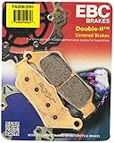
- Complete Double-H Sintered Brake Pad Change Kit includes 2 EBC FA409HH Front Brake Pads and 1 EBC FA409HH Rear Brake Pad
- Double-H Sintered Brake Pads deliver high performance and are well known as the EBC flagship sintered high-performance brake pad
- ECE R 90 brake safety approved and TUV tested, these ultra high friction HH rated brake pads remain a market leader above the rest as nothing else beats the performance of the Double-H Sintered Brake Pad
- Manufactured in the US in the state-of-the-art sintering plant in Ohio, Double-H Sintered Brake Pads perform well in all weather conditions be it dry or wet and have a high longevity lasting for many miles

- Features the highest friction HH rating for maximum stopping power, made in the USA from sintered copper alloy like original pads for longer life and perfect braking
- Stainless steel radiator plates are fitted to reduce heat transfer into bikes hydraulics where required
- The unique double segment vented design improves braking under all riding conditions, keeping the pads cooler and preventing pad drag and overheat or fade
- EBC removed the iron powders commonly used in many sintered pads that cause the pad to weld to the disc under corrosion when the bike is parked and replaced it with stainless powder
- Uses EBCs SB101C friction material which completely eliminates brake noise, improves the pads heat cycling capability and improves feel at the lever

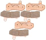
- 【Fitment】Fit for Harley Davidson Motorcycle ▶ Electra Glide FLHT 2008-2020 ▶ Night Rod VRSCD 2006-2011 ▶ Road Glide FLTR 2008-2020 ▶ Road King FLHR 2008-2020
- 【Fitment】 ▶ Street Glide FLHX 2008-2020 ▶ Street Rod VRSCR 2006-2007 ▶ Tri Glide FLHTCUTG 2008-2013 2019-2020 ▶ Ultra Limited FLHTK 2014-2020 ▶ V-Rod VRSC 2005-2017
- 【Material】1. With copper plating base is good for dissipation 2.Sintered by copper and tin formula compound is designed to any poor condictions.
- 【OEM#】41854-08 42850-06 42897-06 42897-08 FA409. 【Repalcement OEM#】42850-06A 42897-06A
- 【Package】Brake Pads Set x 3. Not included instruction manual. Easy to install

- Premium Brake Pads for Your Motorcycle or ATV: Brake Pads fit for 2008-2022 FLHR Road King FLHX Street Glide + 2008-2020 FLHTCU Ultra Classic Electra Glide & FLHRC Road King Classic & VRSCDX Night Rod, 2015-2022 Road Glide FLTRX Limited & FLHXS Street Glide Special & FLTRXS Road Glide Special + 2015-2021 FLHTK Electra Glide Ultra LTD & FLHTKL Electra Glide Ultra LTD Low, 2016-2020 FLTRU Road Glide Ultra + 2007-2020 VRSCDX Night Rod Special + 2009-2020 VRSCF V-Rod Muscle
- High-Performance Braking: Our brake pads are made from the highest quality Carbon Fiber materials and are designed to provide superior stopping power, ensuring that you can stop your motorcycle or ATV safely and quickly when you need to.
- Quiet and Durable: ECCPP brake pads are designed to be quiet and long-lasting, so you can enjoy a smooth and noise-free ride while also getting the most out of your investment.
- Easy to Install: Installing our brake pads is a breeze, and can be done by anyone without the need for any special tools. We've designed our brake pads to fit perfectly onto your motorcycle or ATV, so you can get back on the road in no time.
- Satisfaction Guaranteed: We're confident that you'll love ECCPP brake pads, and we stand behind them with our satisfaction guarantee. If for any reason you're not completely satisfied, we offer a hassle-free return policy.

- All shoes are radius ground and edge trimmed
- Package Dimensions: 15.748 H x 1.016 L x 12.192 W (centimetres)
- Package Weight: 0.227 kilograms
- Country of Origin : Wales
- Made using high pressure die cast alluminium platforms with bonded brake linings
 Brakes FA409HH Disc Brake Pad Set" />
- Made using high pressure die cast alluminium platforms with bonded brake linings
- All shoes are radius ground and edge trimmed
- Features lead in and lead out chamfers at lining ends
- Original equipment style brake shoe springs included

- Premium Brake Pads for Your Motorcycle or ATV: Brake Pads fit for SUZUKI GSXR600 GSXR750 GSXR 600 GSXR 750 K6/K7/K8/K9/L0 2006 2007 2008 2009 2010; GSXR1000 K7/K8 2007 2008 2009 2010; GSX1300 RK8/RK9/RL0/RL1/RL2 2008 2009 2010 2011 2012 Fitment: for SUZUKI DL1000 AL4/AL5/AL6/AL7/AL8/AL9 V-Strom(ABS) 2014 2015 2016 2017 2018 2019 2020; DL1000XT XAL8/XAL9 V-Strom(ABS) 2018 2019 2020
- High-Performance Braking: Our brake pads or brake shoes are made from the highest quality Carbon Fiber materials and are designed to provide superior stopping power, ensuring that you can stop your motorcycle or ATV safely and quickly when you need to.
- Quiet and Durable: ECCPP brake pads are designed to be quiet and long-lasting, so you can enjoy a smooth and noise-free ride while also getting the most out of your investment.
- Easy to Install: Installing our brake pads is a breeze, and can be done by anyone without the need for any special tools. We've designed our brake pads to fit perfectly onto your motorcycle or ATV, so you can get back on the road in no time.
- Satisfaction Guaranteed: We're confident that you'll love ECCPP brake pads, and we stand behind them with our satisfaction guarantee. If for any reason you're not completely satisfied, we offer a hassle-free return policy.

- Made using high pressure die cast alluminium platforms with bonded brake linings
- All shoes are radius ground and edge trimmed
- Features lead in and lead out chamfers at lining ends
- Original equipment style brake shoe springs included
Last update on 2024-04-12 / Affiliate links / Images from Amazon Product Advertising API
This product presentation was made with AAWP plugin.