
| “This site contains affiliate links for which OEMDTC may be compensated” |
NHTSA ID Number: 10165596
Manufacturer Communication Number: 059-Z01-23
Summary
Dexter DX7.5 (Formally Model 750E) Brake Actuator Installation Instructions
1 Affected Product
Equipment
| BRAND | PART NO. | PRODUCTION DATES |
| DEXTER AXLE CO | DEXTER AXLE CO | |
INSTALLATION INSTRUCTIONS
Dexter DX7.5 (Formally Model 750E) Brake Actuator
| # | TDE Part # | DX Part # | Description |
| 1A | 70519K -Disc
70519KD -Drum |
K68-525-20 | Brake Master Cylinder Kit: master cylinder and cap, 4 mounting screws with washers, 2 rollers with matching nuts and bolts |
| 1B | 11286 | 054-239-00 | Disc Brake Solenoid – used with Disc Brake Actuators |
| 2 | 70412 | 068-563-00 | Latch Kit Assembly, with Drop-NGo™ Coupler,(for serial numbers 17927 and above) |
| 3 | 50317 | 074-485-00 | Emergency Stop Cable (E-stop/Breakaway) |
| 4 | 50301 | 074-477-00 | Safety Cable with stainless steel pin – Includes mounting screw |
| 5 | 70462K | K68-524-00 | Actuator Covers, Includes: front and rear cover plates and 4 mounting screws |
| 6 | 48986A | 068-572-00 | Master Cylinder Fill Cap with internal bladder, 2.25” Opening (E-Models) |
| 7 | 48845 | 074-472-00 | Safety Spring with two mounting screws |
IMPORTANT: READ AND UNDERSTAND THE ENTIRE INSTRUCTION/ASSEMBLY PROCEDURE BEFORE INSTALLATION.
The DX7.5 works by the “surge” or “push” of the trailer toward the tow vehicle. This automatically synchronizes the trailer brakes with the tow vehicle axle brakes. When the trailer pushes against the tow vehicle, the actuator telescopes together and applies the force to the master cylinder, supplying hydraulic pressure to the brakes. The built in dampening shock absorber retards the telescoping shock against the hitch ball.
| CAUTION |
| Brake laws sometimes are minimum standards and you may wish to add additional brakes to your trailer. Read your tow vehicles owner’s manual on towing capacity and other towing recommendations before installing brakes or this actuator. |
Read your vehicle’s owner manual on towing capacity and other towing recommendations before installing brakes or this actuator. The DX7.5 Actuator is completely assembled and ready to bolt into place, if not already installed. Manufactured for tongue sizes: 3”x 3”, 3”x 4” & 3”x 5”.
- Bolt the actuator to the tongue-using grade 5 bolts 1/2 inch in diameter, 4 inches long. Lightweight tongues, less than 11 gauge, require spacer tubes inside the tongue for reinforcement. Attachment strength should equal or exceed 1-1/2 times trailer G.V.W.R.
- Hydraulic brake lines should be installed on the trailer as described in the installation manual supplied with the brakes. Note: Some disc brakes require the use of flexible brake lines at the connection point on the brake caliper. Follow brake manufacturer instructions.
| CAUTION |
|
- Use a pressure type brake bleeder to bleed brakes following manufacturer’s directions. Or, manually bleed the brakes following the instructions on page 3. Check with your state motor vehicle department for laws concerning minimum trailer brake requirements. Some states may require brakes on all axles.
- Road test trailer a short distance to activate the actuator several times. Check fluid level again. Remember, low brake fluid levels will result in hitch ball knocking.
| CAUTION |
| AVOID sharp turns, which can cause the actuator to bind or jackknife against the tow vehicle or cause a bend in the tongue. Either can damage the actuator causing brake failure. AVOID towing trailer across large bumps or dips that may over stress the connection between the trailer and tow vehicle, as this could result in damage to the actuator. |
RATED CAPACITY: Maximum Actuator Capacity: 7500 lbs. Gross Load, 750 lbs. Maximum Tongue Load.
The actual in-service rating is limited to that of the ball and hitch being used or the trailer manufacturer’s G.V.W.R. shown on the certification label, whichever is lower (Note: G.V.W.R. is the Gross Vehicle Weight Rating which includes the trailer and the load weight as a Total Gross Weight).
| CAUTION |
| A minimum of 5% tongue weight and a maximum 10% tongue weight of the trailer G.V.W.R must be located on the hitch ball. The Trailer tongue should be parallel to the ground. Too much weight can cause premature brake actuation and loss of control of the towing vehicle. Too little tongue weight can cause the trailer to fishtail, resulting in loss of control of the tow vehicle and trailer (total trailer weight G.V.W.R. includes weight of the trailer plus load). |
Hitching The Trailer
- DX7.5 will accept 2” or 50mm trailer hitch balls only. Trailer balls larger than 2.00” (50mm) or out of round will not fit the coupler or may result in coupler failure. Balls smaller than 1.95” can cause shock loading and sudden disconnection. Make certain ball latch is in correct position to retain the hitch ball. Push latch until safety latch engages plate below latch. Insert safety pin into forward hole as a safety lock for the hitch ball coupler prior to towing. Do not tow trailer if coupler is damaged.
| CAUTION |
|
- Connect safety cables or chains using crossed pattern under tongue, or follow trailer manufacturer’s directions.
| CAUTION |
| Never allow the coupler latch safety pin to remain in the reverse lockout position hole. After reverse maneuvering, always insert coupler latch safety pin back into coupler latch. FAILURE TO REMOVE SAFETY PIN FROM REVERSE LOCK OUT POSITION HOLE WILL PREVENT FORWARD MOVEMENT BREAKING WHICH CAN RESULT IN SERIOUS PROPERTY DAMAGE, INJURY OR DEATH. |
- Connect actuator breakaway cable S-hook to the tow vehicle only. Do not connect S-hook to the safety cables or chains.
- The breakaway system is designed to only operate after the trailer detaches from the tow vehicle and the safety chains have failed. The breakaway is not a parking brake. Do not use as such.
- If the breakaway is accidentally applied, insert a flat bladed screwdriver into the spring clip on the side of the actuator and pry sideways pressure to release.
| CAUTION |
|
- Any control devices that restrict operation of the actuator cannot be used. This includes certain sway control devices. The actuator must be free to telescope in response to braking requirements.
- Equalizing or weight distributing hitches may be used, that are designed to use with surge brake actuators, allow six to eight inches free chain length.
| CAUTION |
| Failure to remove pin will also prevent forward braking. Pin must be in the lower, forward hole as a safety lock for the hitch ball coupler latch when towing at all times. |
- The actuator is designed for use with Free-Backing trailer brakes. To block braking action, (in order to back up) with other types of brakes including disc brakes, use an electric solenoid. For trailer movement when brakes are not required, place the safety pin in the hole on the side of the actuator housing to block movement of the actuator.
Directions Vehicle Wiring – Brake Solenoid
- Disconnect trailer hitch and any wiring connectors from the vehicle.
- Connect a 14 gauge wire to the backup (reverse) light wire of the vehicle. This wire should be of sufficient length to attach to the existing vehicle/trailer wire receptacle. The end of this wire will require a female end that will match the solenoid male connector wire. Your vehicle may have a 5 wire connection for this purpose.
- For ease of use, tape or band the end of the reverse light wire to the vehicle’s trailer electrical connector.
Maintenance
| CAUTION |
| The exterior of the actuator and brakes should always be rinsed with fresh water after use in corrosive conditions. Before storing trailer, clean brakes and repack the bearings. Failure to properly maintain the actuator could cause serious damage, injury or death. |
- Always check the brake fluid reservoir before using trailer. Make sure it is at least half full. If not, re-fill to ³⁄₈” below the top of the reservoir with DOT 3 brake fluid. Do not use DOT 5 brake fluid. Check for leaks and repair as required. Never reuse brake fluid.
- To extend coupler and ball life, coat both with a thin coating of grease. This will also eliminate squeaking. Wipe clean and renew film each time trailer is used.
- Examine the actuator for bent parts or wear each time the trailer is used. Replace parts as necessary.
- There are no user adjustments on the actuator.
- Actuator travel (shown by coupler roller path) over one inch indicates a need to adjust the brakes or add fluid to the reservoir or a need to bleed the brakes and check connections for leaks. Adjust per instructions found in brake installation manual. In general, back-off adjusters on drum brakes from locked position, as required. Adjust Free-Backing brakes by rotating in forward direction only. Failure to adjust may result in loss of braking. Disc brakes do not require adjustment, check for pad wear.
Bleeding Instructions
- To bleed master cylinder and brakes, install bleeder hose on first wheel cylinder to be bled; if tandem axle trailer, bleed closest axle first, and the closest brake on that axle first. Use a loose end of hose from the bleeder valve submerged in a glass container of brake fluid to observe bubbling (hose must be submerged into clean brake fluid to keep air from traveling back into the brake cylinder). Loosen the bleeder screw located in the wheel cylinder one turn, the system is now open to the atmosphere.
- To pump master cylinder, insert a flat tip screwdriver into the bleeding access port on top, near the front of the actuator cover (See 1A).
- The screwdriver should be at the lowest angle possible to the actuator so that it slides in front of the e-stop bracket (See 1B).
- Screwdriver tip MUST BE IN FRONT of the e-stop bracket and NOT in the slot on the e-stop bracket (See 2A).
- Push the screwdriver forward and back to pump the master cylinder. (See 2B).
- The bleeding operation for that brake is complete when bubbling stops. Be sure to tighten bleeder screw securely. Each wheel cylinder must be bleed until all air is out of the lines. Replenish the brake fluid during the bleeding process so the level does not fall below half full level in the master cylinder reservoir.
- When bleeding and testing is completed, make sure master cylinder is filled to ³⁄₈” below the top of the reservoir and filler cap is securely in place.
Emergency Button Stop
Shown in normal operating position
If button stop cable is showing DO NOT TOW TRAILER. Release emergency stop cable by prying spring out with a flat blade screw driver.
059-Z01-23 2019.09 | 08164-2
059-Z01-23
https://www.nhtsa.gov/recalls?nhtsaId=10165596
https://static.nhtsa.gov/odi/tsbs/2019/MC-10165596-0001.pdf
 Loading...
059-Z01-23
https://www.nhtsa.gov/recalls?nhtsaId=10164361
https://static.nhtsa.gov/odi/tsbs/2019/MC-10164361-0001.pdf
Loading...


- Self-Adjusting Electric Brake: Say goodbye to manual adjustments! Dive into the world of 12" x 2" electric trailer brake assemblies that self-adjust. It's not just smart; it's efficient and gives your trailer that smooth braking touch.
- Hassle-Free Installation: DIY's best friend! Our electric trailer brake is straightforward and a breeze to install. It's ready to install right out of the box and boasts high compatibility. Wherever you are, installation is just a few steps away.
- Built for the Long Haul: Keep on rolling! With a lifespan of up to 30,000 kilometers, these trailer brakes are in it for the long haul, designed for your trailer's daily adventures. Constructed from premium materials, our brakes promise robust durability and resistance to wear and tear.
- Versatility at Its Best: The trailer brake kit has a broad range of applications, including towing trailers, transporting goods, camping trips, and more. It's compatible with Dexter, AL-KO (a brand under the former), and other trailer axles.
- Top-Notch Packaging: When it comes to packaging, we don't just box; we care. Our trailer electric brake kit is packaged above industry standards. Every brake is meticulously checked and wrapped to ensure what you get is nothing short of perfect.
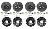
- 4 x trailer 5 on 4.5" hub drum kits + 4 x 10"x2-1/4" electric brakes for Dexter and other brands 3,500 lbs trailer axle
- Drum Bolt pattern: 5 on 4.5", bearing races and 1/2"-20 studs installed, Ref part #. 008-247-05, 84546
- Kits also includ: 4x L68149 inner cone bearings and 4x L44649 outer cone bearings, 4x Grease seals 1.719" x 2.565", 4x E Z lube grease caps with rubber plug; 20 cone wheel nuts 1/2"-20 thread
- Also include: 2 left + 2 right 10"x2-1/4" electric brakes with 3" center bore and 4" mounting bolts circle diamter

- Compatible with: Fit For Alko/ for Dexter/ for Quality, and other brands 3,500lbs trailer axle
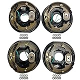
- Kit Includes: 2x 10" x 2-1/4" left electric brake assemblies, 2x 10" x 2-1/4" right electric brake assemblies, 16x spring pad, 16x nut
- Production and Installation: Strictly follow automotive standards and comply with the G3000 standard in the US; Easy to install
- Product Introduction: The AEagle electronic brake features non-asbestos brake linings for superior friction performance, ensuring longevity and enhanced braking capabilities.
- Quality Assurance: 12-month warranty! Tested before shipping.

- Compatible with : For Alko/ for Dexter/ for Quality, and other brands 5,200 lbs 6,000 lbs, and 7,000lbs trailer axle
- Kit Includes: 1x 12" x 2" left electric brake, 1x 12" x 2" right electric brake, 10x bolt, 10x spring pad, 10x nut
- Production and Installation: Strictly follow automotive standards and comply with the G3000 standard in the US; Easy to install
- Product Introduction: The AEagle electronic brake features non-asbestos brake linings for superior friction performance, ensuring longevity and enhanced braking capabilities.
- Quality Assurance: 12-month warranty! Tested before shipping.

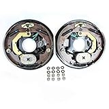
- 10" x 2.25"electric trailer brake assembly (left & right side), fit most 3500lbs - 4000lbs trailer axle; 4-hole mount w/mounting bolt
- Fits the wheel bolt pattern 4 lug,fits spline size #84 steel drum; center hole diameter: 3" ; bolt circle diameter: 4"
- Replace 023-026-00 and 023-027-00;77-10-2;23-105, 23-106,296649;replace Dexter Lippert Al-Ko,etc brake assemblies
- The electric brakes are NOT self adjusting, unlike most drum brakes on cars and trucks,need to be done when installed and periodically thereafter.If you cannot adjust yourself, please find a professional adjustment
- JADODE electric and hydraulic trailer brake parts Making it an Ideal Choice for Travelers Seeking a Hassle-Free Power Solution

- Premium LIBRA OE 12" x 2" self adjusting electric trailer brake assemblies (2 left + 2 right) for two axle
- works with most 5,200 - 7,000 lbs trailer axles in the market
- Center Hole Diameter: 3-1/4", 5 holes mounting,
- Exchange with Dexter brake # 023-180-00/023-181-00
- Self adjusting, no more manual adjusting

- 2-Pack of TruRyde 12" x 2" self-adjusting electric brake assemblies. Contains 2 left and 2 right brake assembly.
- 5 Hole mounting for 5,200 lbs., 6,000 lbs., and 7,000 lbs. trailer axles.
- Comes with mounting bolts, nuts, and lock washers
- Works with Al-Ko, Dexter, Lippert,and Quality Trailer Axles
- Geniune TruRyde Brakes. TruRyde parts are manufactured to automotive standard in ISO/TS-16949 registered factory.
- Pair of 10" x 2.25" TruRdye electric trailer brake assemblies with parts.
- 4 Hole mounting, comes with mounting bolts, nuts, and lock washers
- For Alko, Dexter, Quality, or other popular trailer axle manufacturers.
- TruRyde Brakes
- TruRyde parts are manufactured to automotive standard in ISO/TS-16949 registered factory.
Last update on 2024-06-11 / Affiliate links / Images from Amazon Product Advertising API
This product presentation was made with AAWP plugin.