
| “This site contains affiliate links for which OEMDTC may be compensated” |
January 28, 2021 NHTSA CAMPAIGN NUMBER: 21V029000
Locking Tabs May Break Off During Operation
A damaged positional waterway trolley can become disconnected from the ladder and drop to the ground, increasing the risk of injury or death.
NHTSA Campaign Number: 21V029
Manufacturer Smeal Holding, LLC
Components EQUIPMENT
Potential Number of Units Affected 616
Summary
Smeal Holding, LLC (Smeal) is recalling certain 2009-2020 Aerial Fire Apparatus vehicles equipped with a positional waterway trolley. If the operator attempts to both extend the ladder, and shift from one mode to the other at the same time, the locking tabs can be broken off the locking arms.
Remedy
Smeal will notify owners, and dealers will adjust the proximity switches for those units equipped with a positional waterway mode shift timer interlock system, free of charge. The recall began on March 25, 2021. Owners may contact Smeal customer service at 1-800-867-6478.
Notes
Owners may also contact the National Highway Traffic Safety Administration Vehicle Safety Hotline at 1-888-327-4236 (TTY 1-800-424-9153), or go to www.safercar.gov.
SEOCONTENT-START
Recall Service Bulletin
RSB21-900-001
Page 1 of 8 CPS-FR-0010
Rev: 1.0
21-02
Service Bulletins are intended for use by Professional Technicians only. They are written to guide Professional Technicians in performing service to
vehicles of specific nature in conjunction with industry standards. Professional Technicians are appropriately trained on industry standards and have
the tools and equipment to perform procedures safely and properly.
DATE: 3/10/2021
APPLIES TO: This service bulletin applies to certain 2008 through 2020 model year
Smeal Aerial Fire Apparatus built between January 15, 2009 and January
14, 2021, equipped with a positional waterway and shift timer.
NHTSA/TC Id:
CONDITION: Smeal aerial positional waterway proximity switch out of adjustment
CORRECTION: Adjust proximity switch in accordance with instructions provided below.
LABOR ALLOCATION: 1 hour
CLASSIFICATION: E3
PARTS NEEDED: None
GENERAL INSTRUCTIONS:
Thoroughly review entire service bulletin before starting work. If there are questions or concerns
with steps defined in this service bulletin, contact Spartan Fire LLC. Customer & Product Support
Group.
All applicable industry safety standards must be followed when performing work identified in this
procedure.
Warning: The procedure listed in this work instruction must be performed by a qualified
technician.
Read and follow safety instructions in the operator manual prior to beginning work.
All steps must be completed prior to returning apparatus to service.
Failure to comply with safety instructions may lead to injury or death.
Recall Service Bulletin
RSB21-900-001
Page 2 of 8 CPS-FR-0010
Rev: 1.0
21-02
Service Bulletins are intended for use by Professional Technicians only. They are written to guide Professional Technicians in performing service to
vehicles of specific nature in conjunction with industry standards. Professional Technicians are appropriately trained on industry standards and have
the tools and equipment to perform procedures safely and properly.
Positional Waterway Shift System Description.
The positional waterway monitor is mounted to a trolley that slides on the fly section of the ladder. The
trolley is always locked to either the fly section (water tower mode) or the next lower section (rescue mode)
using a pair of locking tabs on locking arms. The arms are moved by a motor actuator linkage mechanism.
Two proximity switches set to sense the location of a Z-bracket attached to the locking arm linkage
mechanism (prox 1 -water tower, and prox 2-rescue mode).
A third proximity switch (prox 3) is used to sense that the ladder is retracted. Only in the fully retracted
condition is it physically possible for the mode shift to occur and the control logic allows the motor actuator
to move the locking arms and locking tabs from one locking pocket to the other.
When the operator desires to shift between one mode and the other, he/she retracts the ladder, and moves
the mode switch. If prox 3 senses a fully retracted ladder, then the motor actuator begins moving the locking
arm linkage mechanism. Once the Z-bracket moves out of the range of prox 1 or prox 2 a timer is initiated
energizing a blocking valve that keeps the ladder sections from extending. The timer lasts for 10 seconds to
ensure that the actuator motor has completed the mode shift. This prevents ladder extension if the operator
fails to wait for the mode indicator lights to change before moving the ladder extension joystick.
Model Year 2009 Applicability Verification Step
THIS STEP REQUIRED FOR 2009 MODEL YEAR ONLY.
This adjustment procedure is only applicable if the aerial device is equipped with a positional
waterway shift timer and blocking valve feature. The addition of this feature occurred in model
year 2009. Later model years do not require this verification. This procedure is not applicable to
Model years 2008 and earlier. The model year can be found on the FMVSS label in the cab.
Mode Indication Examples
Recall Service Bulletin
RSB21-900-001
Page 3 of 8 CPS-FR-0010
Rev: 1.0
21-02
Service Bulletins are intended for use by Professional Technicians only. They are written to guide Professional Technicians in performing service to
vehicles of specific nature in conjunction with industry standards. Professional Technicians are appropriately trained on industry standards and have
the tools and equipment to perform procedures safely and properly.
If the device you are working on is a model year 2009
Open the service panel on the control console at the turntable.
Look for two timer relays as shown in the figure.
If the timer relays are present, proceed with the next step
If the timer relays are not present, this procedure is not applicable
NOTE: A timer relay and blocking valve upgrade is available for models 2009 and earlier. See your
Smeal Service Facility for details.
Control Console Access Panel
(example shown, consoles may vary)
Timer Relays
(example shown, relay location
may vary
Recall Service Bulletin
RSB21-900-001
Page 4 of 8 CPS-FR-0010
Rev: 1.0
21-02
Service Bulletins are intended for use by Professional Technicians only. They are written to guide Professional Technicians in performing service to
vehicles of specific nature in conjunction with industry standards. Professional Technicians are appropriately trained on industry standards and have
the tools and equipment to perform procedures safely and properly.
Prepare for PROX 1 Adjustment
Park the apparatus in an area where the ladder can be raised and extended off one of the
sides.
Follow the operator manual to deploy the stabilizers
Deploy the aerial device to side of the apparatus
Fully retract the ladder
Elevate the ladder to 20 degrees or higher
Shift the positional waterway to the WATER TOWER mode.
Wait 10 seconds and ensure the WATER TOWER indication has illuminated.
Lower and extend the ladder to a position where the positional waterway trolley can be
accessed from the ground or a from a safe working platform.
Turn OFF the aerial PTO switch (leave the Aerial Master switch in the ON position).
Turn the engine IGNITION switch OFF to stop the engine.
Turn the IGNITION switch to the ON position.
Figure 1: Removing the trolley access panel.
Access Panel
Trolley
Recall Service Bulletin
RSB21-900-001
Page 5 of 8 CPS-FR-0010
Rev: 1.0
21-02
Service Bulletins are intended for use by Professional Technicians only. They are written to guide Professional Technicians in performing service to
vehicles of specific nature in conjunction with industry standards. Professional Technicians are appropriately trained on industry standards and have
the tools and equipment to perform procedures safely and properly.
PROX 1 Adjustment
Locate the positional waterway trolley that secures the waterway monitor to the ladder.
Remove the three T25 Torx screws securing the positional waterway access panel to the
trolley.
Locate the WATER TOWER mode proximity switch (PROX 1)
Loosen the PROX 1 jam nuts
While maintaining downward pressure on the head of PROX 1, observe the indicator lamp
on the tail.
If the indicator lamp is not illuminated, maintain downward pressure on the head and rotate
the upper jam nut clockwise until the light is ON.
Maintain downward pressure and rotate the upper jam nut counterclockwise until the light
goes OFF.
Maintain downward pressure and rotate the upper jam nut clockwise until the light turns
ON.
Maintain downward pressure and rotate the upper jam nut clockwise one additional turn.
Hold PROX 1 and the upper jam nut from rotating while you tighten the lower jam nut
firmly.
Figure 2: Properly adjusted PROX 1 WATER TOWER MODE Proximity Switch showing illuminated indicator light.
Head
Upper Jam Nut
Lower Jam Nut
PROX 1
Indicator Light
Recall Service Bulletin
RSB21-900-001
Page 6 of 8 CPS-FR-0010
Rev: 1.0
21-02
Service Bulletins are intended for use by Professional Technicians only. They are written to guide Professional Technicians in performing service to
vehicles of specific nature in conjunction with industry standards. Professional Technicians are appropriately trained on industry standards and have
the tools and equipment to perform procedures safely and properly.
Confirm PROX 1 Adjustment
Fully retract the ladder
Elevate the ladder to 20 degrees or higher
Shift the positional waterway to the RESCUE mode.
Wait 10 seconds and ensure the RESCUE indication has illuminated.
Shift the positional waterway to the WATER TOWER mode.
Wait 10 seconds and ensure the WATER TOWER indication has illuminated.
Shift the positional waterway to the RESCUE mode.
Wait 10 seconds and ensure the RESCUE indication has illuminated.
Leave the system in the RESCUE mode.
Recall Service Bulletin
RSB21-900-001
Page 7 of 8 CPS-FR-0010
Rev: 1.0
21-02
Service Bulletins are intended for use by Professional Technicians only. They are written to guide Professional Technicians in performing service to
vehicles of specific nature in conjunction with industry standards. Professional Technicians are appropriately trained on industry standards and have
the tools and equipment to perform procedures safely and properly.
Prepare for PROX 2 Adjustment
Lower and extend the ladder to a position where the positional waterway trolley can be
accessed from the ground or a from a safe working platform.
Turn OFF the aerial PTO switch (leave the Aerial Master switch in the ON position).
Turn the engine IGNITION switch OFF to stop the engine.
Turn the IGNITION switch to the ON position.
Figure 3: Properly adjusted PROX 2 RESCUE MODE Proximity Switch showing illuminated indicator light.
Head
Upper Jam Nut
Lower Jam Nut
PROX 2
Indicator Light
Recall Service Bulletin
RSB21-900-001
Page 8 of 8 CPS-FR-0010
Rev: 1.0
21-02
Service Bulletins are intended for use by Professional Technicians only. They are written to guide Professional Technicians in performing service to
vehicles of specific nature in conjunction with industry standards. Professional Technicians are appropriately trained on industry standards and have
the tools and equipment to perform procedures safely and properly.
PROX 2 Adjustment
Locate the RESCUE mode proximity switch (PROX 2)
Loosen the PROX 2 jam nuts
While maintaining upward pressure on the head of PROX 2, observe the indicator lamp on
the tail.
If the indicator lamp is not illuminated, maintain upward pressure on the head and rotate
the lower jam nut clockwise until the light is ON.
Maintain upward pressure and rotate the lower jam nut counterclockwise until the light
goes OFF.
Maintain upward pressure and rotate the lower jam nut clockwise until the light turns ON.
Maintain upward pressure and rotate the lower jam nut clockwise one additional turn.
Hold PROX 2 and the lower jam nut from rotating while you tighten the upper jam nut
firmly.
Secure the positional waterway access panel to the trolley using the three T25 Torx screws.
Confirm PROX 2 Adjustment
Fully retract the ladder
Elevate the ladder to 20 degrees or higher
Shift the positional waterway to the WATER TOWER mode.
Wait 10 seconds and ensure the WATER TOWER indication has illuminated.
Shift the positional waterway to the RESCUE mode.
Wait 10 seconds and ensure the RESCUE indication has illuminated.
Confirm Blocking Valve Operation
Fully retract the ladder
Elevate the ladder to 20 degrees or higher
Shift the positional waterway to the WATER TOWER mode.
Wait 10 seconds and ensure the WATER TOWER indication has illuminated.
Shift the positional waterway to the RESCUE mode.
Wait for the WATER TOWER indication to go OFF, then immediately move the extension
joystick to extend the ladder. The ladder should NOT move during the brief time that both
mode indications are OFF.
Shortly after the RESCUE mode indication has illuminated the ladder should be able to
extend.
Repeat these steps shifting from RESCUE mode to WATER TOWER mode.
Return Apparatus to Service
Shift the positional waterway as required to the desired default mode
Follow the operator manual instructions to stow the device and the stabilizers.
SEOCONTENT-END
12 Affected Products
Vehicle
| MAKE | MODEL | YEAR |
| SMEAL | AERIAL | 2009-2020 |
8 Associated Documents
Recall Quarterly Report #2, 2021-2
RCLQRT-21V029-8752.PDF 211.236KB
 Loading...
Recall Acknowledgement
RCAK-21V029-2300.pdf 645.849KB
Loading...
Recall 573 Report
RCLRPT-21V029-2102.PDF 215.084KB
Loading...
Recall Quarterly Report #1, 2021-1
RCLQRT-21V029-0615.PDF 211.134KB
Loading...
Recall 573 Report- Amendment 1
RCLRPT-21V029-6536.PDF 215.086KB
Loading...
Recall Quarterly Report #3, 2021-3
RCLQRT-21V029-1491.PDF 211.324KB
Loading...
Safety Bulletin
RCSB-21V029-1149.pdf 1092.289KB
Loading...
Recall Quarterly Report #4, 2021-4
RCLQRT-21V029-9364.PDF 211.438KB
Loading...
Latest Recalls Documents
https://www-odi.nhtsa.dot.gov/acms/cs/documentList.xhtml?docId=21V029&docType=RCL
| “This site contains affiliate links for which OEMDTC may be compensated” |

- Pushbutton Switches
- Capacitive proximity switch M30 CR30-15DN cylinder level sensor electrode long distance
- Material: paper
- Switch type: Push Button
- Color: One Color
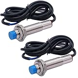
- Product Name : Inductive Proximity Switch;Model : LJ12A3-4-Z/AX;Theory : Inductive Sensor;Wire Type : 3 Wire Type (Brown, Blue, Black)
- Switch Appearance Type : Cylinder Type, Metal Shell;Output Type : NPN NC;
- Detecting Distance : 4mm(+/-10%);Supply Voltage : DC 6-36V Output Current : 300mA;Detect Object : Iron;Column Sensor Diameter : 10.4mm/0.4";Thread Diameter : 12mm/0.5"
- Total Size : 66 x 21mm/ 2.6'' x 0.8'' (L*Max.D);Cable Length : 1.16m/35.7'';External Material : Plastic, Metal
- Net Weight :100g;Color : Blue Tone, Black ;Package Content : 2 x Inductive Proximity Switch

- 🌟Inductive Proximity Switch Type: SN04-N, 3 Wire NPN NO. Detecting Distance: 4mm. Supply Voltage: 5-30VDC, Current Output: 300mA.
- 🌟LED working indicator: signal indicator, when sensing metal objects the light is on for normally open, the light is off for normally closed.
- 🌟Wiring Method: Brown connect to Positive, Blue connect to Negative, Black connect to Load (signal output).
- 🌟When proximity switch is close to some target object, it will send out control signal. Widely used for machine tool industry, frequency counters and other automatic control system, or you can use it for DIY 3D Printer.
- 🌟You will get 4pcs inductive proximity switch + 4pcs SN Bracket


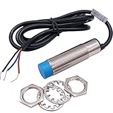
- Product Name : Inductive Proximity Switch;Model : LJ18A3-8-Z/BX;Wire Type : DC 3 Wire Type (Black, Brown, Blue);Switch Appearance Type : Cylinder Type
- Theory : Inductive Sensor;Output Type: NPN NO(Normal Open);Thread diameter: 18mm : 18mm;Detecting Distance : 8mm
- Supply Voltage : DC 6-36V;Current Output : 300mA;Detect Object : Iron
- Operating Temperature : -25C to +55C (Non-freezing Condition);Size : 7 x 3cm/2.8'' x 1.2'' (L*Max. Dia);Cable Length : 103cm / 40.55"
- External Material : Plastic, Alloy;Net Weight : 160g;Package Content : 2 x Inductive Proximity Switch

- 【Product Name】:Inductive Proximity Switch; Wire Type : DC 3 Wire Type (Black, Brown, Blue);Switch Appearance Type : Cylinder Type.
- 【Supply Voltage】 : DC12-24V;Current Output : 300mA;Detect Object : Iron,When proximity switch is close to some target object, it will send out control signal.
- 【Theory】 : Inductive Sensor;Output Type : NPN NO(Normal Open);Thread Diameter : 10.5mm/0.41";Head Diameter : 11.8mm/0.46".
- 【LED working indicator】: signal indicator, when sensing metal objects the light is on for normally open, the light is off for normally closed.
- 【Applied Range】:It is widely used in machine, paper making, light industry for limiting station, orientation taking count, speeding trial ect.

- LJ12A3-4-Z/AX inductive proximity switch; Theory: Inductive sensor; Wire Type: 3 wire type (brown, blue, black)
- Switch appearance type : Cylinder type, metal shell; Output type : NPN NC (Normally Closed); Detecting distance: 4mm(+/-10%)
- Supply voltage: DC 10-30V output current : 200mA; Respond Frequency: 0.5KHZ
- Detect object: Iron; Column sensor diameter: 10.4mm/0.4""""; Thread diameter: 12mm/0.5"""", Total size : 66 x 21mm/ 2.6'' x 0.8'' (L*Max.D); Cable length : 115.5cm/45''
- LJ12A3-4-Z/AX is a component widely used for detecting, controlling and non-contact switching
- Special attention: After the switch is installed, the sensing distance needs to be adjusted, otherwise, there will be no response when the switch is turned on.There are two friends recently. The reaction product does not work, First note: our products are 100 % tested before they leave the factory. Solution: 1. Turn Switch control sensing distance behind the product; 2 .Send us an email and we will send you a new one.
- Product Name : Capacitive Proximity Switch; Model : LJC18A3-H-Z/BX;Wire Type : DC 3 Wire Type (Brown, Black, Blue);Theory : Capacitance Sensor; Output Type : NPN NO(Normal Open);Diameter of Head : 16mm; Thread Diameter:18mm; Detecting Distance : 1-10mm
- Operating Temperature : -25 to +65 Celsius (Non-freezing Condition);Size : 7.5 x 3cm / 3"x 1.2"(L*Max. Dia);Cable Length : 120cm/47";External Material : Plastic, Alloy
- Detecting Object : Metal or Nonmetal Material; Supply Voltage : DC 6-36V;Current Output : 300mA;Response Frequency : 100Hz
- Net Weight : 85g;Color : Silver Tone, blue, Gray; Package Content : 1 x Capacitive Proximity Switch

- This proximity sensor has excellent performance, high sensitivity, good linearity, fast response, and can detect high-speed moving targets.
- This proximity sensor is not affected by external electromagnetic field interference when working, has strong anti-interference performance, and can detect all types of target materials.
- This proximity switch can choose NPN/PNP/NC/NO multiple output modes to meet different selection requirements
- This proximity switch adopts non-contact working mode, which will not scratch or damage the target surface due to contact, and has a long service life.
- This proximity sensor has a simple and compact mechanical structure, small size, and easy integration and installation.
Last update on 2024-06-18 / Affiliate links / Images from Amazon Product Advertising API
This product presentation was made with AAWP plugin.