| “This site contains affiliate links for which OEMDTC may be compensated” |
October 19, 2020 NHTSA CAMPAIGN NUMBER: 20V643000
Outriggers may Bend Affecting Handling
If the outriggers bend, it can negatively affect vehicle handling, increasing the risk of a crash.
NHTSA Campaign Number: 20V643
Manufacturer Heartland Recreational Vehicles, LLC
Components STRUCTURE
Potential Number of Units Affected 104
Summary
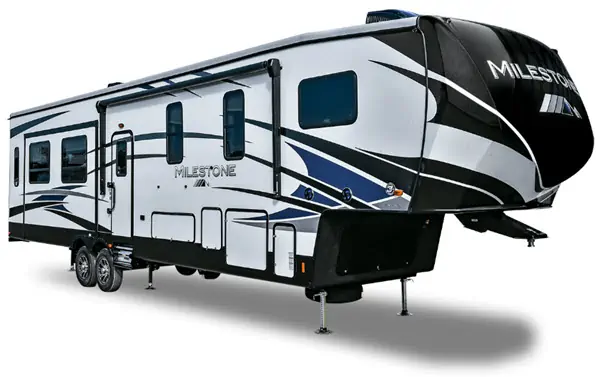
Heartland Recreational Vehicles, LLC (Heartland) is recalling certain 2019-2020 Milestone fifth-wheel trailers. The outriggers may bend due to loading within the rear storage area.
Remedy
Heartland will notify owners, and dealers will reinforce the frame, free of charge. The recall began December 4, 2020. Owners may contact Heartland customer service at 1-877-262-8032.
Notes
Owners may also contact the National Highway Traffic Safety Administration Vehicle Safety Hotline at 1-888-327-4236 (TTY 1-800-424-9153), or go to www.safercar.gov.
Purpose
This document refers to the chassis of the models listed to add reinforcement supports to key areas lacking wall structure, outrigger bending and negative effects on the frame’s camber.
Safety
Read and understand all instructions before installing or operating this product. Adhere to all safety labels. This document provides general instructions. Many variables can change the circumstances of any procedure, i.e. the degree of difficulty involved in the service operation and the ability level of the individual performing the operation. This document cannot begin to plot out procedures for every possibility, but will provide the general instructions for effectively installing, removing or servicing the system. In the event the skill level required is too advanced or the procedure too difficult, a certified technician should be consulted before performing the necessary operation. Failure to correctly install, remove or service the system may result in voiding the warranty, inflicting injury or even death.
SEOCONTENT-START
Rev: 11.13.20 Page 1 CCD-0004048
Recall Number: 20V643
Product: 360RD Frame Fix
HEARTLAND MILESTONE RECALL 20V643
360RD FRAME FIX
Purpose
This document refers to the chassis of the models listed to add reinforcement supports to key areas lacking
wall structure, outrigger bending and negative effects on the frame’s camber.
Safety
Read and understand all instructions before installing or operating this product. Adhere to all safety labels.
This document provides general instructions. Many variables can change the circumstances of any
procedure, i.e. the degree of difficulty involved in the service operation and the ability level of the individual
performing the operation. This document cannot begin to plot out procedures for every possibility, but will
provide the general instructions for effectively installing, removing or servicing the system. In the event the
skill level required is too advanced or the procedure too difficult, a certified technician should be consulted
before performing the necessary operation. Failure to correctly install, remove or service the system may
result in voiding the warranty, inflicting injury or even death.
The “WARNING” symbol above is a sign that a procedure has a safety risk involved and may cause
death, serious personal injury, severe product and/or property damage if not performed safely and
within the parameters set forth in this document.
The “CAUTION” symbol above is a sign that a procedure has a safety risk involved and may cause
personal injury, product and/or property damage if not performed safely and within the parameters
set forth in this document.
Failure to remove flammable objects or obstructions may result in death, serious injury or
property damage.
Lift the trailer by the chassis. Do not go under the trailer unless it is properly supported.
Unsupported trailers can fall and may result in death, serious injury or property damage.
Moving parts can pinch, crush or cut. Keep clear and use caution.
Rev: 11.13.20 Page 2 CCD-0004048
Recall Number: 20V643
Product: 360RD Frame Fix
HEARTLAND MILESTONE RECALL 20V643
360RD FRAME FIX
All outrigger and hanger location dimensions are measured from the top rail of the I-beam.
Do NOT measure from the bottom I-beam rail.
Measuring from the bottom I-beam rail will off-set the axles by an inch or more.
Outrigger Location Dimensioning
Hanger Location Dimensioning
I-beam Top Rail
Outriggers
Front
Rev: 11.13.20 Page 3 CCD-0004048
Recall Number: 20V643
Product: 360RD Frame Fix
HEARTLAND MILESTONE RECALL 20V643
360RD FRAME FIX
Preparation
Note: Solid ORANGE lines in this document refer to using a plasma cutter/blow torch to remove
components. Solid RED/BLK lines refer to using a welder to add frame components per instructions
and image references. Solid WHT/BLK lines in this document refer to making marks on the frame
with a non-permanent marker. Dashed BLUE lines indicate the centerline of an area. GREEN lines
indicate a designated area.
Resources Required
Tools Required
• Proper protective equipment
for welding
• Welder
• Floor jacks
• Jack stands
• Pinbox tripod
• Tape measure
• Non-permanent marker
• Grinder
• Blow torch/plasma cutter
• Fire blankets
• Fire extinguisher
• Lint-free wipes
• Black spray paint
Components Required
Heartland Milestone 360RD Service Kits
Callout Part# Description Qty
A 2020135537 Heartland Milestone 360RD 11 Ga Kit (Include B, E-I) 1
B 742307 Crush Tube, 2″ x 4″ x 1/8″ – L156″ (11 Ga) 2
C 2020135538 Heartland Milestone 360RD 7 Ga Kit (Includes D, E-I) 1
D 2020135536 Crush Tube, 2″ x 4″ x 3/16″ – L156″ (7 Ga) 2
11 Ga and 7 Ga Service Kit Common Parts
E 742307 Cross-member Tube, 2″ x 3″ x 1/8″ – L66 1/2″ (12 Ga) 3
F 106183 Long Hanger, 2 3/8″ x 3 7/8″ x 3 7/8″ x 1/4″ – L3″ (4 Ga) 2
G 106181 Short Hanger, 3″ x 2 35/64″ x 1 55/64″ x 1 55/64″ (4 Ga) 4
H 102403 Outrigger (Roadside), 1 1/2″ x 6 15/16″ x 5/64″ – L13 3/8″ (14 Ga) 7
I 102404 Outrigger (Curbside), 1 1/2″ x 6 15/16″ x 5/64″ – L13 3/8″ (14 Ga) 7
Always lift trailer by the frame, never the axle or suspension. Do not go under the trailer unless it
is properly supported by jack stands. Unsupported trailers can fall causing death or serious injury.
This repair should only be completed by an authorized service technician.
1. Use a pinbox tripod to support the 5th Wheel pin.
2. Lift front and rear of chassis/frame with floor jacks and stabilize with jack stands according to
manufacturer’s recommendations.
Note: LCI recommends rear jack stands should be 12”-24” from rear of the trailer and front jack stands
should be at least 12” from the landing gear.
Rev: 11.13.20 Page 4 CCD-0004048
Recall Number: 20V643
Product: 360RD Frame Fix
HEARTLAND MILESTONE RECALL 20V643
360RD FRAME FIX
Failure to remove flammable objects, obstructions, tires, axles or additional suspension
components may result in death, serious injury or property damage.
3. Remove all screws from the underbelly material and remove underbelly material.
4. Remove any wires, heat ducts, gas lines, water/holding tanks and underbelly material that is against
the I-beams or that might cause a fire hazard.
Note: If an item cannot be removed, protect it with a fire barrier.
5. Cover tires and exposed floor with a barrier to protect from welding heat and splatter.
Procedure
Note: Some chassis components in the following images are not shown for clarity.
See figure 1 for affected area of chassis.
Fig. 1
Affected Area
Inspection
Area
Inspection of Frame
Inspect the bottom flange of the I-beam from the center spring hanger to three feet behind the rear spring
hanger.
1. If there are any kinks or significant waves/buckles, then order the 7 Ga kit.
2. All other applications should use the 11 Ga kit.
Rev: 11.13.20 Page 5 CCD-0004048
Recall Number: 20V643
Product: 360RD Frame Fix
HEARTLAND MILESTONE RECALL 20V643
360RD FRAME FIX
Fig. 2
Removal of Existing Hangers
On the curbside and roadside of the chassis:
1. With a non-permanent marker, mark the center location of each hanger (Fig. 2).
2. Use a blow torch or plasma cutter to remove the old hangers from the I-beams (Fig. 2). Use care not to
damage the I-beam during the cutting process.
3. Use a grinder to smooth the cut area on the I-beam.
Installation of Service Kit
Note: Refer to Heartland Milestone 360RD Service Kits chart for appropriate crush tube usage.
1. Place two crush tubes on sawhorses or other supports.
2. From one end of the tube, measure to the center of the tube (59″) and mark the location (Fig. 3).
3. From the center mark, measure out in each direction 30 1/2″. Mark each new location (Fig. 3).
Curbside Chassis with Hangers
Roadside Chassis with Hangers
Do NOT damage the I-beam when cutting. Damage to the I-beam can cause irreparable damage,
rendering the trailer unsafe.
Inspection Area – 3 ft
Inspection Area – 3 ft
Center of Existing Hangers
Cut Lines
Rev: 11.13.20 Page 6 CCD-0004048
Recall Number: 20V643
Product: 360RD Frame Fix
HEARTLAND MILESTONE RECALL 20V643
360RD FRAME FIX
4. Clamp new 4 Ga long hanger (Callout F) at the center mark made in step 2 (Fig. 3). Align center of
hanger’s through-hole with the crush tube’s center mark.
5. Clamp two new 4 Ga short hangers (Callout G), one at each 30 1/2″ mark made in step 3 (Fig.3). Align
center of each hanger’s through-hole with the crush tube’s mark.
6. Check to make sure the hanger centerline markings made on the crush tube align with the old hanger
centerline markings made on the I-beam.
Fig. 3
59″
30 1/2″ 30 1/2″
Markings Long Hanger
Short Hangers (x2)
7. Fully weld the hangers to the tube (Fig. 4).
Fig. 4
Weld All Around Hangers
Cross-Member Tube Locations
With the crush tube weldments still supported on sawhorses, use a tape measure and non-permanent
marker to mark on the crush tubes the locations of the three 12 Ga (Callout E) cross-member tubes.
Note: Cross-member tube markings should mirror each other—roadside to curbside.
1. Locate the first cross-member tube (Fig. 5A) as follows:
A. Measure back from the front end of each weldment 1/4″ (Fig. 5) and mark the location.
B. Measure up from the bottom of each weldment 1/4″ (Fig. 5) and mark the location.
2. Locate the second cross-member tube (Fig. 5B) as follows:
A. Measure back from the front of the first cross-member tube 88 1/4″ (Fig. 5) and mark the location.
B. Measure up from the bottom of each weldment 1/4″ (Fig. 5) and mark the location.
Rev: 11.13.20 Page 7 CCD-0004048
Recall Number: 20V643
Product: 360RD Frame Fix
HEARTLAND MILESTONE RECALL 20V643
360RD FRAME FIX
Fig. 5
Roadside Crush Tube Weldment Front
1/4″ 1/4″
65 1/4″ 88 1/4″
C B A
Marking
Lines
3. Locate the third cross-member tube (Fig. 5C) as follows:
A. Measure back from the front of the second cross-member tube 65 1/4″ (Fig. 5) and mark
the location.
B. Measure up from the bottom of each weldment 1/4″ (Fig. 5) and mark the location.
Crush Tube Installation
Install crush tube weldments as follows:
1. From the front of the curbside I-beam rail, measure 177″ towards the rear (Fig. 6). Mark the location on
the I-beam.
2. Place one end of a crush tube weldment at the mark (Fig. 7)—making sure the short hanger closest to
the end of the tube is oriented towards the front of the chassis (Fig. 3)—center the length of the tube
along the bottom flange of the I-beam, then clamp in‑place.
Rev: 11.13.20 Page 8 CCD-0004048
Recall Number: 20V643
Product: 360RD Frame Fix
HEARTLAND MILESTONE RECALL 20V643
360RD FRAME FIX
Curbside View 177″
Fig. 6
3. From the front of the roadside I-beam rail, measure 177″ towards the rear. Mark the location on the
I-beam.
4. Place one end of the second crush tube weldment at the mark (Fig. 7)—making sure the short hanger
closest to the end of the tube is oriented towards the front of the chassis (Fig. 3)—center the length of
the tube along the bottom flange of the I-beam, then clamp in‑place.
Fig. 7
Crush Tube Weldment
Location Mark
I-beam Bottom Flange
Curbside View
Curbside Jack
Mounting Bracket
Roadside Jack
Mounting Bracket
Rev: 11.13.20 Page 9 CCD-0004048
Recall Number: 20V643
Product: 360RD Frame Fix
HEARTLAND MILESTONE RECALL 20V643
360RD FRAME FIX
T-2
W-2
X-1
X-2
W-1
T-1
Axle Hanger
on Center
Axle Hanger
on Center
Fig. 8
5. Check the alignment to make sure crush tube weldments are square (Fig. 8), and adjust if necessary.
Refer to TI-058 Axle Hanger Measurement Procedure – Double Axle for additional information. Go to
https://lci-support-doc.s3.amazonaws.com/technical-information-sheets/axles-and-suspension/ccd-
0001920.pdf. Make sure that the curbside and roadside hangers are aligned with each other.
Rev: 11.13.20 Page 10 CCD-0004048
Recall Number: 20V643
Product: 360RD Frame Fix
HEARTLAND MILESTONE RECALL 20V643
360RD FRAME FIX
Curbside View
Wrap Weld
Around Corners
Weld Tube
to Jack
Mounting
Bracket Tab
Wrap Weld
Around Corners
6. Stitch weld 3″ every 12″ – 15″, both inside and outside along the I-beam (Fig. 9), on both the curbside
and roadside crush tube weldments.
7. Tube must be welded fully on both ends. Wrap 5″ weld around all four corners (Fig. 9).
Note: Tube MUST also be fully welded above hangers on both sides.
Fig. 9
Rev: 11.13.20 Page 11 CCD-0004048
Recall Number: 20V643
Product: 360RD Frame Fix
HEARTLAND MILESTONE RECALL 20V643
360RD FRAME FIX
Fig. 10
Curbside Roadside
Weld All Around
Cross-Member Tube Installation
1. Install the first 12 Ga (Callout E) cross-member tube as follows:
A. Align both ends of the cross-member tube with the measurement markings on the curbside and
roadside crush tube weldments (Figs. 5A and 10). Clamp tube in-place.
B. Fully weld each end of the cross-member tube to the crush tube weldments (Fig. 11).
Fig. 11
I-beam
12 Ga Crossmember
Tube Crush Tube
Jack Mounting Weldment
Bracket
Front
Measurement
Markings
Rev: 11.13.20 Page 12 CCD-0004048
Recall Number: 20V643
Product: 360RD Frame Fix
HEARTLAND MILESTONE RECALL 20V643
360RD FRAME FIX
Fig. 12
Front
Crush Tube
Weldment
Crossmember
Tube
2. Install the second 12 Ga (Callout E) cross-member tube as follows:
A. Align both ends of the cross-member tube with the markings on the curbside and roadside crush
tube weldments (Figs. 5B and 12). Clamp tube in-place.
B. Fully weld each end of the cross-member tube to the crush tube weldments (Fig. 11).
3. Install the third 12 Ga (Callout E) cross-member tube as follows:
A. Align both ends of the cross-member tube with the markings on the curbside and roadside crush
tube weldments (Figs. 5C and 13). Clamp in-place.
B. Fully weld each end of the cross-member tube to the crush tube weldments (Fig. 11).
Measurement
Markings
Fig. 13
Crush Tube
Weldment
I-beam
Rear
Crossmember
Tube
Measurement
Markings
Rev: 11.13.20 Page 13 CCD-0004048
Recall Number: 20V643
Product: 360RD Frame Fix
HEARTLAND MILESTONE RECALL 20V643
360RD FRAME FIX
Outrigger Replacement and Reinforcement
Install four 14 Ga curbside outriggers (Callout I) as follows:
1. From the top and front of the curbside I-beam rail, use a tape measure to measure towards the rear the
following dimensions (Fig. 14) and mark with a non-permanent marker the locations on the I-beam:
A. 199 3/4″
B. 236 3/4″
C. 269 3/4″
D. 310 1/2″
Fig. 14
2. Replace any bent/damaged outriggers.
A. Unfasten damaged outrigger from floor. Save fastening hardware for later reuse.
B. Cut (Fig. 15A), grind and clean areas of removed outriggers.
C. Install appropriate replacement outrigger (Callout H or I) at its previously marked (step 1) location.
I. Cut enough tab from the replacement outrigger such that the underside of the cut tab is flush
with the top of the I-beam’s rail (Fig. 16A). This will keep the outrigger’s mounting surface
flush to the floor.
II. Fully weld along the outside and bottom of the replaced outrigger (Fig. 16B).
III. Weld the underside edge of the cut tab to the outside edge of the rail (Fig. 17A).
3. Clamp a new 14 Ga outrigger back-to-back (Fig. 18) to an existing outrigger.
Note: Whenever possible, slide the new outrigger’s tab between the I-beam rail and the floor (Fig. 18A).
When not possible, cut enough tab from the outrigger (Fig. 18B) such that the underside of the cut
tab is flush with the top of the I-beam’s rail.
A. Make sure the tops of the mated outriggers are flush to one another (Fig. 19A) and their underside
surfaces are flush to the top of the I-beam rail.
B. Fully weld along the outside and bottom of the mated outrigger (Fig. 19B).
C. Fully weld along the underside of the outrigger’s tab and rail (Fig. 19C).
310 1/2″
236 3/4″
199 3/4″
269 3/4″
Curbside
Front
Rev: 11.13.20 Page 14 CCD-0004048
Recall Number: 20V643
Product: 360RD Frame Fix
HEARTLAND MILESTONE RECALL 20V643
360RD FRAME FIX
A
A
Fig. 15
Fig. 16 Fig. 17
A
B
A
Rev: 11.13.20 Page 15 CCD-0004048
Recall Number: 20V643
Product: 360RD Frame Fix
HEARTLAND MILESTONE RECALL 20V643
360RD FRAME FIX
A B
Added
Outrigger
Fig. 18
Fig. 19
C
Existing
Outrigger
A
Added
Outrigger
B
4. Clamp a new 14 Ga outrigger back-to-back (Fig. 16) to a replaced outrigger.
Note: Whenever possible, slide the new outrigger’s tab between the I-beam rail and the floor. When not
possible, cut enough tab from the outrigger (Fig. 20A) such that the underside of the cut tab is flush
with the top of the I-beam’s rail.
A. Make sure the tops of the mated outriggers are flush to one another (Fig. 20B) and their underside
surfaces are flush to the top of the I-beam rail.
B. Fully weld along the outside and bottom of the mated outrigger (Fig. 20C).
C. Fully weld along the underside of the outrigger’s tab and rail (Fig. 20D).
Rev: 11.13.20 Page 16 CCD-0004048
Recall Number: 20V643
Product: 360RD Frame Fix
HEARTLAND MILESTONE RECALL 20V643
360RD FRAME FIX
Fig. 20
Install three new 14 Ga roadside outriggers (Callout H) as follows:
1. From the top and front of the roadside I-beam rail, use a tape measure to measure towards the rear the
following dimensions (Fig. 21) and mark with a non-permanent marker the locations on the I-beam:
A. 236 3/4″
B. 269 3/4″
C. 310 1/2″
Roadside
236 3/4″
269 3/4″
310 1/2″
B
Added
Outrigger
B
Replaced
Outrigger
A
C
D
Fig. 21
Rev: 11.13.20 Page 17 CCD-0004048
As a supplier of components to the RV industry, safety, education and customer satisfaction are our primary concerns. Should you
have any questions, please do not hesitate to contact us at (574) 537-8900 or by email at customerservice@lci1.com. Self-help tips,
technical documents, product videos and a training class schedule are available at lci1.com or by downloading the MyLCI app.
HEARTLAND MILESTONE 360RD FRAME FIX
TSB Number: 03-001-20
Product: Frames and Chassis
Date: 09.15.20
2. Replace any bent/damaged outriggers.
A. Unfasten damaged outrigger from floor. Save fastening hardware for later reuse.
B. Cut (Fig. 15A), grind and clean areas of removed outriggers.
C. Install appropriate replacement outrigger (Callout H or I) at its previously marked (step 1) location.
I. Cut enough tab from the replacement outrigger such that the underside of the cut tab is flush
with the top of the I-beam’s rail (Fig. 16A). This will keep the outrigger’s mounting surface
flush to the floor.
II. Fully weld along the outside and bottom of the replaced outrigger (Fig. 16B).
III. Weld the underside edge of the cut tab to the outside edge of the rail (Fig. 17A).
3. Follow the curbside outrigger installation instructions to install roadside outriggers. Refer to steps 3
and 4 and figures 15 and 16 in the curbside outrigger installation instructions.
Post Service Kit Installation Procedure
1. Allow all new welded areas to completely cool.
2. Clean new welded area with a stiff wire brush to remove any weld and paint flakes.
3. Wipe new weld areas with clean, lint-free wipes.
4. Apply black spray paint to new weld areas.
5. Allow paint to fully dry before removing any protective coverings.
6. Remove all protective coverings.
7. Re-attach floor to outriggers with previously removed hardware.
8. Reinstall any wires, heat ducts, gas lines, water/holding tanks, screws and underbelly material that was
previously removed.
9. Lift front and rear of chassis/frame with floor jacks to remove jack stands and pinbox tripod.
10. Carefully lower chassis/frame to ground.
SEOCONTENT-END
2 Affected Products
Vehicle
| MAKE | MODEL | YEAR |
| HEARTLAND | MILESTONE | 2019-2020 |
8 Associated Documents
Recall Quarterly Report #3, 2021-2
RCLQRT-20V643-2845.PDF 211.317KB
 Loading...
Recall 573 Report – Amendment 1
RCLRPT-20V643-3869.PDF 214.362KB
Loading...
Remedy Instructions and TSB
RCRIT-20V643-1158.pdf 4101.274KB
Loading...
Recall Quarterly Report #2, 2021-1
RCLQRT-20V643-7600.PDF 211.237KB
Loading...
Recall Acknowledgement
RCAK-20V643-1821.pdf 244.903KB
Loading...
Defect Notice 573 Report
RCLRPT-20V643-7842.PDF 214.344KB
Loading...
Recall Quarterly Report #1, 2020-4
RCLQRT-20V643-9848.PDF 211.134KB
Loading...
Recall Quarterly Report #4, 2021-3
RCLQRT-20V643-7786.PDF 211.42KB
Loading...
Latest Recalls Documents
For the Latest and Most Recent Recalls Information Visit the link below…
https://www-odi.nhtsa.dot.gov/acms/cs/documentList.xhtml?docId=20V643&docType=RCL
| “This site contains affiliate links for which OEMDTC may be compensated” |

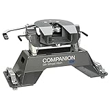
- Compatible with the Ford OEM hitch platform
- Fully articulating head allows front to back and side to side pivoting. Cam action latching handle for easy release, even when parked on unlevel sites.
- Cam action latching handle for easy release, even when parked on unlevel sites.
- 25,000 lb GTW/6,250 lb VTW
- Made in America with a Limited Lifetime Warranty

- Fully articulating head allows front to back and side to side pivoting.
- Cam action latching handle for easy release, even when parked on unlevel sites.
- Polyurethane bushings provide a quiet, rattle-free towing experience.
- 20,000 lb GTW/5,000 lb VTW
- Made in America with a Limited Lifetime Warranty

- DUAL-PIVOT HEAD. This CURT 5th wheel hitch features a dual-pivoting head that provides 10 degrees of lateral movement to promote smooth, stable towing
- AUTO-LOCK. The coupler of this 5th wheel hitch has an automatic locking feature to make the coupling process easier and more secure
- ANTI-RATTLE. To help reduce rattling and vibration at the coupling point, this 5th wheel hitch is equipped with an anti-rattle skid plate
- TESTED SAFETY. This 16K 5th wheel hitch is tested according to SAE J2638 specifications for safety and is rated to tow up to 16,000 lbs. gross trailer weight and 4,000 lbs. vertical load (limited to lowest-rated towing component)
- VERSATILE FIT. This 5th wheel hitch comes with standard legs to easily and securely mount onto any industry-standard 5th wheel base rails, such as CURT base rails #16104 and #16204 (base rails and brackets sold separately)

- Compatible with the 2020-2024 Chevrolet/GM OEM hitch platform
- 12" of slide for additional turning clearance
- Fully articulating head allows front to back and side to side pivoting. Cam action latching handle for easy release, even when parked on unlevel sites. Polyurethane bushings provide a quiet, rattle-free towing experience.
- 20,000 lb GTW/5,000 lb VTW
- Made in America with a Limited Lifetime Warranty

- Compatible with the 2020-2024 Chevrolet/GM OEM hitch platform
- Fully articulating head allows front to back and side to side pivoting. Cam action latching handle for easy release, even when parked on unlevel sites.
- Cam action latching handle for easy release, even when parked on unlevel sites.
- 25,000 lb GTW/6,250 lb VTW
- Made in America with a Limited Lifetime Warranty
- Compatible with the Ford OEM hitch platform
- Fully articulating head allows front to back and side to side pivoting. Cam action latching handle for easy release, even when parked on unlevel sites.
- Cam action latching handle for easy release, even when parked on unlevel sites.
- 20,000 lb GTW/5,000 lb VTW
- Made in America with a Limited Lifetime Warranty
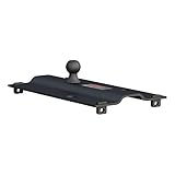
- MAXIMUM FUNCTIONALITY. This unique gooseneck hitch is a 5th wheel to gooseneck adapter. It is designed to drop into existing 5th wheel base rails in your truck bed and enable gooseneck towing
- 5TH WHEEL FIT. For versatile application, this gooseneck 5th wheel hitch fits any industry-standard 5th wheel rails. It provides a standard 2-5/16-inch gooseneck ball for ready coupling of a gooseneck trailer
- DEPENDABLE TOWING. This 5th wheel gooseneck hitch is tested and rated to tow 25,000 lbs. gross trailer weight and 6,250 lbs. vertical load (limited to lowest-rated towing component)
- CORROSION-RESISTANT. For reliable weather resistance, this gooseneck hitch adapter is shielded in a highly durable carbide powder coat finish. This tough finish easily outlasts exposure to rain, snow, dirt and other corrosive elements
- EASY TO INSTALL. This 5th wheel to gooseneck hitch adapter easily drops into the 5th wheel hitch rails and is secured with 4 included hitch pins. It can be positioned over the truck axle or flipped and set for 3 inches of rearward displacement

- SELF-RESETTING - This A-series 5th wheel hitch features a unique, ergonomic handle and extra-wide head to make coupling your 5th wheel trailer easier than ever. After uncoupling, the handle self-resets to the ready-to-couple position
- FULL ARTICULATION - This 5th wheel hitch provides controlled towing of your 5th wheel camper with its patented head technology. The head is built on a cast yoke with poly-torsion inserts that reduce shock loads, chucking and noise at the coupling point
- COUPLING INDICATOR - Built into this 5th wheel hitch is a 3-position indicator that shows the coupling status. It conveniently shows if the 5th wheel hitch is coupled, uncoupled or ready to tow
- TESTED STRENGTH - This 5th wheel hitch is tested and rated for 25,000 lbs. gross trailer weight and 6,250 lbs. vertical load (limited to lowest-rated towing component). It is tested according to SAE J2638 specifications
- VERSATILE FIT - This 5th wheel kit fits select model years of the Chevrolet Silverado and GMC Sierra 2500 HD and 3500 HD and Ford F-250, F-350 and F-450 Super Duty with 5th wheel prep package
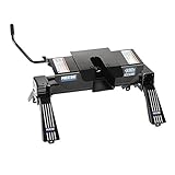
- Item may ship in more than one box and may arrive separately
- 16,000 lbs. Capacity; 4,000 lbs. pin weight capacity
- 6" side-to-side pivot to better accommodate hook-ups on uneven ground and easier towing
- Adjustment heights from 14 1/2" to 18", fore-and-aft and side-to-side pivot
- Two-jaw locking system with locking jaw handle

- TESTED 20K STRENGTH - Unlike other light-duty 5th wheels, CrossWing is built with steel versus aluminum, allowing it to provide a 20K rating, tested to SAE J2638 specs (Lippert trailer chassis approved. Will not void warranty)
- 65% LIGHTER - Even with its robust 20,000-pound rating, CrossWing is still much lighter weight than traditional 5th wheel hitches, with the main body only weighing 60 pounds
- INCREASED COMFORT - Engineered with ShockDrop technology, CrossWing features a cushioned isolator that helps deter jerking, jarring, vibrations and rattling for a more comfortable ride while towing
- NO GUESSWORK - Hooking up with the CrossWing hitch is made simple with its unique coupling system. It eliminates guesswork by offering a visible contact surface while the head channel guides the kingpin into place
- ONE-PERSON INSTALL - With its lightweight design and the strategic placement of grip points for added comfort, this light-duty 5th wheel hitch can be installed in the truck bed with just one person (fits industry-standard rails; will not fit X5)
Last update on 2024-04-14 / Affiliate links / Images from Amazon Product Advertising API
This product presentation was made with AAWP plugin.