| “This site contains affiliate links for which OEMDTC may be compensated” |
August 28, 2020 NHTSA CAMPAIGN NUMBER: 20V524000
Brake Lever/Pedal Travel Required To Decelerate
Hydrogen in the braking system can reduce the brake lever’s ability to activate the brakes, increasing the risk of a crash.
NHTSA Campaign Number: 20V524
Manufacturer Piaggio Group Americas. Inc.
Components SERVICE BRAKES, HYDRAULIC
Potential Number of Units Affected 123
Summary
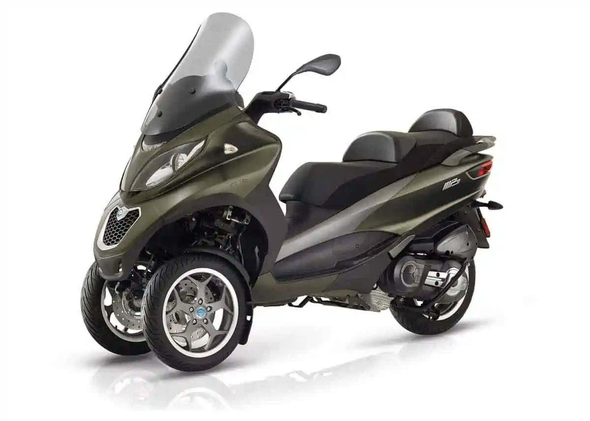
Piaggio Group Americas, Inc. (Piaggio) is recalling certain 2019-2020 MP3 500 motorcycles. The brake lines may have been improperly galvanized, allowing hydrogen to be released into the brake fluid.
Remedy
Piaggio will notify owners, and dealers will perform a complete brake system flush, free of charge. The recall began September 10, 2020. Owners may contact Piaggio customer service at 1-212-380-4433. Piaggio’s number for this recall is PP2ZZQ1904_MP3.
Notes
Owners may also contact the National Highway Traffic Safety Administration Vehicle Safety Hotline at 1-888-327-4236 (TTY 1-800-424-9153), or go to www.safercar.gov.
Date: September 18, 2020
Contact: Technical Services
Subject: NHTSA Recall 20V524 – Brake bleeding campaign
Recall Communication: Campaign Code: PP2ZZQ2002
Affected Models: A specific range of:
2019 MP3 500
2020 MP3 500
Concern: Piaggio USA has identified the possibility of non-conformity in the zinc plating surface treatment on the brake hose terminal fittings. This can cause a chemical reaction with the brake fluid itself and result in excessive travel from the front or rear brake lever. This situation can cause reduced braking or stopping ability and can lead to a loss of control or a crash, increasing the risk of injury.
Cause: A non-conforming zinc plating process on the brake hose fittings causes hydrogen gas to escape into the brake fluid, leading to a loss of braking ability.
Correction: A brake system fluid replacement with comprehensive bleed (if necessary) must be performed based on the results of an initial test described in this bulletin. Two different claiming coupons are available based on the test results. If a vehicle passes the test, only a limited bleed procedure to replace the brake fluid is required (Coupon 1). If a vehicle fails the test, a comprehensive bleed procedure and fluid replacement is required (Coupon 2)
Please prioritize the repair following the guidelines below:
Customer vehicles: Perform recall at first available opportunity
Vehicles in stock: Perform recall at the PDI stage before sale to customer
Please note that after the initial test is performed and the repair made under either Coupon 1 or Coupon 2, the vehicle must be left alone for 24 hours and the test repeated to verify results and document with final photos. Six photos are required when finishing each claim;
( 3 “before” photos taken during the initial test and 3 “after” photos taken during the final test after repairs)
All affected vehicles are blocked from warranty registration until the campaign has been completed in the PWM warranty system.
Note: It is imperative to perform this recall before the vehicle is sold and/or leaves the dealership. Using the PWM warranty system, click on “Campaigns”, then “Campaign Reports” to view ALL VINS in your inventory that require a technical update or recall. This list can be filtered by searching for a specific Campaign Description, a Frame number, the Campaign start date or Coupon state. This recall has the description, “Brake Fluid Replacement and brake system bleeding”. Customers can also check for themselves if their vehicle is subject to this recall by using this site: https://static.piaggio.com/recall/form–piaggio_en.html
Checking your entire inventory for campaigns:
Owner Notification: Each owner of a vehicle included in this recall will be notified by first class mail. In this letter Piaggio USA will describe the details of the concern, the cause, and the correction addressed by this recall. In addition, Piaggio USA asks that each owner contact their respective Piaggio/Vespa dealer to arrange for an appointment to have the parts and labor required of this recall completed.
Please make every effort to accommodate your recall customers within your existing service schedule. In addition, Piaggio USA has provided each recall customer with details of the TREAD Act Reimbursement program. In short, this program provides a plan to reimburse a customer who has already paid for the same repair or update as described in the recall documents. A copy of the Owner Notification and the TREAD Act Reimbursement letters are included at the end of this bulletin.
Important Note: Under the National Traffic and Safety Act of 1966 as amended, if there has been a recall campaign, dealers must assure that all new vehicles and new items of replacement equipment are free of safety defects and comply with all applicable Federal Motor Vehicle Safety Standards at the time of delivery to the customer. This means that dealers may not deliver new motor vehicles or new items of replacement equipment to consumers unless the safety defect or noncompliance has been remedied before delivery.
VIN Identification (For individual VINS):
- Go to the Dealer Portal https://dealerportal.piaggiocom/ and enter your Username and Password. From the left hand menu, click on “Piaggio Business Service”
- Select “Other functions” in left-hand main menu, then “Vehicle History” in the sub-menu.
- Enter the VIN number next to “Frame number” and click “Retrieve Data”
- Click the box next to “Active Campaigns” to view any recalls or technical updates that apply to the VIN. This recall has the description, “Brake fluid replacement and brake system bleeding”.
- The status of the campaign can be determined from the status column. Status examples are shown below:
TO DO: a claim for the campaign has not be entered
SUSPENDED: a dealer in the network has entered a claim for the campaign, but has not “carried out” the claim. Please contact the warranty administrator-ihenry@piaggiogroupamericas.com
PERFORMED: a claim for the campaign has been entered and carried out by a dealer
Warranty Claiming:
- From the PWM warranty system menu, click on “Campaigns”. Under the heading “Enter Campaigns” enter the VIN next to “Frame number” and click “Search”.
- Under “Campaign Code”, click on the underlined ID code for this campaign.
- Brake fluid replacement and brake system bleeding
Please choose either Coupon 1 or 2 based on test results on page 5 of this bulletin
- Under “ Coup. Data”, enter the KM/Mi. of the vehicle.
- Click the “SAVE” icon at the top of the claim.
Important note: In order to begin the payment process, Campaign submission must be followed by “Carrying-Out” the recall or technical update campaign. This is the last step in the claim process, confirming that the work was actually performed by your dealer. “Carrying-out” recalls or updates is done under the function “State Management” in PWM. On claims found under State Management, you must click on the Wrench icon under the column “Perform work” for the respective claim. All types of claims (Normal warranty claims/ Technical update claims /Recall claims) are carried out under State Management.
Labor reimbursement and necessary parts:
Coupon 1 Brake fluid replacement (Passes initial test) service coupon for replacement of the brake fluid, (reimbursement of brake fluid, the O-Ring and the labor required)
- Minutes of labor: 110 minutes
- Reimbursement for brake fluid and O-Ring: $OIL150*
Pages 8-23 refer to brake fluid replacement for all three masters (front, rear, pedal)
Coupon 2 Replacing brake fluid and bleeding brake system (Fails initial test) service coupon for the replacement of the brake fluid and comprehensive bleeding of the brake system,
(reimbursement of the brake fluid, the O-Ring and the labor required)
- Minutes of labor: 335 minutes
- Reimbursement for brake fluid and O-Ring: $OIL150*
Pages 24-45 -Bodywork removal and foot pedal pushrod check/adjustment
Pages 45-57-Component removal and Rear brake bleeding
Pages 57-64 -Component removal and Front brake bleeding
Pages 65-68- Activation of ABS module with PADS with manual bleed afterwards.
Pages 68-69- Pedal master cylinder bleeding
Pages 69-73 -Brake fluid replacement (front master, rear master, pedal master)
* Piaggio has included a flat rate of $8.28 in the service coupon, identified by the code $OIL150, to cover the cost for the purchase of approximately 500 cc of brake fluid and O-Ring. We also remind you that the O-Rings to carry out the tests (one per vehicle) will be sent to the dealer by P&C.
IMPORTANT
The service coupons must include a number of photos included as attachments. Instructions for each photo are given in the procedure. 6 photos are required when finalizing each claim in STATE MANAGEMENT ( 3 “Before” and 3 “After” photos). Photos are not entered when the claim is first submitted, only when finishing the claim to declare the work is complete.
TEST PROCEDURE
Below is an operational diagram to aid workshop operations
Test OK -> All three checks must be met to test OK.
1. Distance measured to the right-hand lever ≥ 95 mm
2. Distance measured to the left-hand lever ≥ 95 mm
3. Brake pedal consistent
Test not OK -> If ANY of the three measures fail
* The dealer will be responsible for analyzing the outcome of the test.
** If the customer cannot leave the vehicle immediately in the workshop, schedule the intervention within a maximum of 6 days; illustrating to the customer, as also reported in the online use and maintenance booklet (https://dealerportal.piaggiogroup.com), that the efficiency of the braking system must be checked before each use.
*** The bleeding procedure must only be performed on the part of the system that did not pass the Test; e.g.:
1. Left-hand lever + Right-hand lever + Pedal-> NOT OK -> perform the complete procedure + fluid replacement
2. Left-hand lever -> NOT OK -> Bleeding of rear brake + complete replacement of fluid
3. Right-hand lever -> NOT OK -> Bleeding of front brake + complete replacement of fluid
4. Pedal -> NOT OK -> Bleeding of combined braking system + complete replacement of fluid
Warning: for points 2 and 3 (one of the two levers NOT OK ) the control must always be performed on the pedal after having restored the manual circuit.
TEST –Brake levers and pedal (Required for both coupons)
Pull the rear brake lever and hold in position by fitting the O-ring, p/n 006731, onto the lever and handgrip as shown in the photo.
Hold the fixed jaw of the vernier calliper against the handgrip as shown in the photo.
N.B: To show the position of the vernier calliper more clearly, this photo has been taken with the counterweight removed.
Measure the distance between the outer edge of the handgrip and the end of the brake lever.
Minimum permissible distance: 95 mm
N.B: The measurement must be made with the vernier calliper perfectly aligned with the direction of movement of the lever.
NOTE: Take a photo of the position of the left hand lever when pulled completely before any repairs and attach to the service coupon when finalizing claim.
Repeat the procedure for the front brake lever to measure the distance between the outer edge of the handgrip and the end of the lever when the lever is pulled completely.
Minimum permissible distance: 95 mm
NOTE: Take a photo of the position of the right hand lever when pulled completely before any repairs and attach to the service coupon when finalizing claim.
If possible, pull the two levers of the manual brake master cylinders forcefully at the same time.
While holding the levers, check the travel of the combined braking system pedal.
N.B: To ensure accurate test results, the pressure in the combined braking system circuit must not exceed the pressure values in the manual braking circuits to the levers.
With an efficient pedal, the perceived actuation stroke will essentially correlate to taking up mechanical play and a very short stroke of the piston.
This means that the hydraulic compression of the pedal will be barely noticeable.
NOTE: Take a photo of the position of the combined braking system pedal when pressed completely before any repairs, and attach to the service coupon when finalizing the claim. The photos for the preliminary checks described above were taken on a vehicle in proper working order.
Brake fluid replacement (Preparation steps for Coupon 1)
Remove the windscreen, removing the 4 fastener screws with the relative spacers.
Remove the 4 fastener screws and the protective grille of the radiator.
Remove the Y-shaped cover, detach the respective fastener lugs.
Remove the 2 fastener screws and the lower cover of the windscreen mount.
Open the glove box and unscrew the 2 fastener screws indicated.
Remove the 2 front fastener screws of the windscreen mount complete with the relative washers.
Remove the windscreen mount, removing the remaining 4 fastener screws with the relative shaped spacers.
Remove the fastener screw and remove the right hand centre access panel.
Remove the silencer guard, unscrewing and removing the 2 fastener screws with the relative metal flange rings.
Loosen the screw of the metal clamp fastening the silencer to the exhaust pipe.
Loosen the check nut of the silencer fastener system.
Remove the fastener screw of the bracket.
Remove the pin and remove the retainer bracket.
Remove the mounting screw of the silencer with the relative washers, and detach and remove the silencer from the exhaust pipe.
Remove the split pin and the relative cap.
Engage the parking brake and remove the nut with the spacer.
Remove the lower fastener bolt of the shock absorber.
Remove the upper fastener bolt of the shock absorber.
Remove the right hand shock absorber with the 4 spacers.
Remove the screw with the washer.
Remove the plastic guard panel, unscrewing the remaining 2 upper screws.
Remove the speed sensor, unscrewing the 2 fastener screws.
Remove the second fastener screw of the stand.
Remove the 2 fastener nuts of the carrier arm.
Lift the mudguard and detach and remove the carrier arm.
Remove the rear wheel, unscrewing and removing the 5 fastener screws with the relative washers.
Rear brake fluid replacement (left lever) Coupon 1
Connect the container for collecting brake fluid to the rear calliper bleed nipple.
Remove the 2 screws and the lid of the reservoir complete with gasket.
Operate the rear brake lever repeatedly.
Keep the master cylinder under pressure.
Open the bleed nipple of the rear calliper, discharging the fluid under pressure.
Tighten the bleed nipple.
Operate the master cylinder and repeat the bleeding sequence, draining the original brake fluid.
Keep an eye on the brake fluid level in the reservoir to avoid the intake of air.
Continue filling the rear brake circuit until approximately 120 cc has been drained into the collector container.
Fill the rear master cylinder reservoir to the max. level.
Fit the cover of the rear reservoir.
Front brake fluid replacement (Right lever ) Coupon 1
Open the reservoir of the front master cylinder.
Change the brake fluid in the left hand front brake circuit (working on Left front wheel)
Refill the right hand master cylinder reservoir, draining the used fluid under pressure from the bleed nipple of the left hand front calliper.
N.B: Do not operate the lever of the master cylinder repeatedly while the bleed nipple is open.
Continue filling the left hand front brake circuit until approximately 120 cc has been drained into the collector container.
N.B: The photo illustrates the position of the steering where the reservoir of the front master cylinder offers the best filling conditions.
Next, change the brake fluid in the right hand front circuit. (working on Right front wheel)
Refill the right hand master cylinder reservoir, draining the used fluid under pressure from the bleed nipple of the right hand front calliper.
N.B: Do not operate the lever of the master cylinder repeatedly while the bleed nipple is open.
Continue filling the right hand front brake circuit until approximately 120 cc has been drained into the collector container.
N.B: The photo illustrates the position of the steering where the reservoir of the front master cylinder offers the best filling conditions.
Combined braking system fluid replacement (Foot pedal master cylinder) Coupon 1
Remove the fastener screw of the combined braking system master cylinder reservoir and top up to the max. level.
Pull the two brake levers forcefully and hold to pressurise the manual brake master cylinders.
At the same time, press the combined braking system master cylinder pedal.
Then, bleed the front servo pump.
Replace the brake fluid.
Fill the combined braking system master cylinder reservoir, adding 4 times the volume of new fluid necessary to fill the reservoir system to flush the system, draining the fluid contained in the circuit under pressure from the bleed nipple of the front brake servo pump.
N.B: Do not operate the pedal repeatedly while the bleed nipple is open.
Refit the rear wheel with the 5 screws and the relative washers.
Tighten the screws to a torque of 20-25 Nm.
Continue with the reassembly of the carrier arm, paying attention to the correct application of all the tightening torques.
Pay attention to the correct positioning of the gasket and to the correct fastening of the slip joint clamp screw.
Tightening torque 16÷18 Nm.
N.B: Lack of torque leads to sealing problems.
Excessive torque blocks the joint with abnormal stresses on the exhaust system.
Refit the remaining bodywork components.
Once the operations are completed, the vehicle must be kept in the workshop for 24 hours without moving it or operating the brake levers or pedals.
At the end of the 24 hours, the repeat the checks (Tests) already performed at the beginning of this procedure, in order to document the outcome of the test and obtain the final photos needed to finish the claim.
TEST – Final checks
1. Take a photo illustrating the travel measured for the RH lever with the vernier calliper (minimum permissible value 95 mm), and attach to the service coupon when finalizing claim.
2. Take a photo illustrating the travel measured for the LH lever with the vernier calliper (minimum permissible value 95 mm), and attach to the service coupon when finalizing claim.
3. Carry out the pedal firmness test, taking a photo of the values measured and attaching it to the service coupon when finalizing claim.
If the required values of not attained, technical support must be contacted to determine the cause of the problem.
Brake fluid bleeding and replacement operation- COUPON 2
Pages 24-45 -Bodywork removal and foot pedal pushrod check/adjustment
Pages 45-57-Component removal and Rear brake bleeding
Pages 57-64 -Component removal and Front brake bleeding
Pages 65-68- Activation of ABS module with PADS with manual bleed afterwards.
Pages 68-69- Pedal master cylinder bleeding
Pages 69-73 -Brake fluid replacement (front master, rear master, pedal master)
Remove the windscreen, removing the 4 fastener screws with the relative spacers.
Remove the 4 fastener screws and the protective grill of the radiator.
Remove the front fastener screw of the 2 mudguard.
Remove the 2 fastener screws of the front cover, situated inside the wheel housings.
Remove the 2 upper screws fastening the front cover.
Remove the front cover, unscrewing the 2 Torx screws.
Remove the 2 upper screws fastening the bodywork mount.
Remove the bodywork mount, unscrewing the remaining 2 Torx screws.
Remove the rear fastener screw of both mudguards.
Remove the upper fastener screw of both mudguards.
Remove both front mudguards, pushing towards the front of the vehicle to detach all the fastener lugs.
Remove the Y-shaped cover, detach the respective fastener lugs.
Remove the 2 fastener screws and the lower cover of the windscreen mount.
Open the glove box and unscrew the 2 fastener screws indicated.
Remove the 2 front fastener screws of the windscreen mount complete with the relative washers.
Remove the windscreen mount, removing the remaining 4 fastener screws with the relative shaped spacers.
Remove the 2 mounting brackets, unscrewing the 4 fastener screws and removing the screws together with the relative washers.
Disconnect the headlamp unit connector, releasing the safety lock clip.
Remove the front headlamp unit, unscrewing the 4 fastener screws.
Disconnect the 2 connectors of the front turn indicators.
Remove the 2 lower fastener screws of the front leg shield.
Remove the 2 upper fastener screws of the leg shield.
Remove the front leg shield, unscrewing the remaining 4 fastener screws.
Remove the rear view mirrors, unscrewing and removing the fastener nuts with the relative washers.
Remove the center cover panel of the handlebar carefully, lifting it up from the rear.
Remove the fastener screws and disconnect and remove the handlebar switchgear sets.
Remove the fastener screws of the handlebar cover, situated in the space under the handlebar switchgear sets
Remove the 3 fastener screws of the handlebar cover, situated in the space under the center cover panel
Remove the upper handlebar cover, disengaging the 4 fastener tabs.
Disconnect the connector of the ambient temperature sensor.
Remove the lower handlebar cover, loosening the 4 fastener screws.
Remove the dashboard trim panel, unscrewing the 2 fastener screws.
Remove the 2 fastener screws of the button panel.
Release the 2 clips and disconnect the button panel, disconnecting the 4 electrical connectors.
Remove the cover of the bag holder hook, unscrewing the 2 fastener screws.
Remove the center fastener screw of the cover panel.
Remove the cover panel with the knee pads, unscrewing the 4 screws situated inside the suspension compartment.
Remove the fastener screw of the expansion tank cap access cover.
Unscrew the expansion tank cap.
Remove and remove the fastener screw of the expansion tank with the relative washers.
Release the fastener clip of the reverse switch cable.
Remove the 2 rear fastener screws of the dashboard.
Using a pair of circlip pliers, turn the bezel of the ignition switch anticlockwise to align the word ‘ON’ with the key slot.
Remove the bezel of the ignition switch complete with metal ring.
Release the lock tab and disconnect the power connector of the USB port.
Release the lock tab and disconnect the flying lead connector of the dashboard connector.
Release the lock tab and disconnect the dashboard connector.
Remove the complete dashboard, turning it towards the right hand side of the vehicle.
Remove the 3 fastener screws and the battery compartment cover.
Remove the 2 screws fastening the saddle support system.
Remove the fastener screw and the cover of the internal saddle sensor.
Disconnect the sensor connector.
Remove the seat, undoing the 2 fixing screws.
Remove the grab handle cover, unscrewing and removing the 4 fastener screws with the relative washers.
Use a screwdriver to prise out the 2 blanking plugs of the holes for the 2 front fastener screws of the grab handle.
Remove the rear grab handle, undoing and removing the 5 screws with the relative washers.
Remove the 2 screws fastening the rear cover.
Remove the rear cover, detaching the 2 spring clips.
Remove the lower screws of both side covers.
Remove the upper screws of both side covers.
Remove the central screws of the side covers.
Remove the rear screws of both flanks.
On both flanks, remove the 2 screws near the passenger footpegs.
Remove the 2 screws fastening the center cover, near the saddle.
Remove the side covers, detaching the 5 clips.
Disconnect the electrical connector of each rear light unit.
Remove the fastener screw and remove the right hand center access panel.
Remove the 2 fastener screws of the right hand center cover.
Remove the fastener screw and remove the left hand center access panel.
Remove the 2 fastener screws of the left hand center cover.
Remove the fuel cap.
Remove the center cover, detaching the cable for internal saddle sensor and the fuel filler cover release cable.
Remove the fastener plate of the right hand floor mat, unscrewing the 3 fastener screws.
Remove the right hand floor mat with the 6 spacers for the fastener plate screws.
Remove the front fastener screw of the right hand footboard.
Remove the lower fastener screw of the right hand footboard.
Remove the rear M6 fastener screw of the right hand footboard.
Remove the upper M6 fastener screw of the right hand footboard with the relative washer.
Remove the right hand rear footrest platform, unscrewing the clamp screw and unscrewing and removing the 2 Torx screws complete with the relative washers.
Remove the 4 screws connecting the underside of the footboard to the footboard.
Lift up the gaiter and remove the upper part of the combined braking system pedal, unscrewing the 2 fastener screws.
Separate the two parts of the footboard and remove from the vehicle.
Check that the combined braking system pedal is against the retainer bracket of the brake light switch when the pedal itself in the rest position.
Press the pedal to release the brake light switch and reveal the clearance created between the pedal arm and the actuator pin of the brake light switch
This photo illustrates an incorrectly adjusted pedal with excessive clearance between the pedal arm and brake light switch( pushrod too short)
It is more serious, however, if there is no clearance between pedal arm and brake light switch when the pedal is in the rest position. (pushrod too long)
This is extremely dangerous as it may cause the rear brake circuit to remain under pressure even when the pedal is released.
In case of an incorrectly adjusted combined braking system pedal, move the boot out of the way, loosen the check nut and adjust the length of the master cylinder pushrod with pliers.
Adjust the length of the pushrod so that the brake light actuator pin has no remaining clearance with the pedal arm at a distance of approximately 0.40 mm from the end stop rest. ( adjust pushrod so pedal arm just touches the end of the switch pin, with the .40mm gauge installed between the switch retainer bracket and pedal arm)
Refit the boot correctly after adjusting.
Remove the silencer guard, unscrewing and removing the 2 fastener screws with the relative metal flange rings.
Loosen the screw of the metal clamp fastening the silencer to the exhaust pipe.
Loosen the check nut of the silencer fastener system.
Remove the fastener screw of the bracket.
Remove the pin and remove the retainer bracket.
Remove the mounting screw of the silencer with the relative washers, and detach and remove the silencer from the exhaust pipe.
Remove the split pin and the relative cap.
Engage the parking brake and remove the nut with the spacer.
Remove the lower fastener bolt of the shock absorber.
Remove the upper fastener bolt of the shock absorber.
Remove the right hand shock absorber with the 4 spacers.
Remove the screw with the washer.
Remove the plastic guard panel, unscrewing the remaining 2 upper screws.
Remove the speed sensor, unscrewing the 2 fastener screws.
Remove the second fastener screw of the stand.
Remove the 2 fastener nuts of the carrier arm.
Lift the mudguard and detach and remove the carrier arm.
Remove the rear wheel, unscrewing and removing the 5 fastener screws with the relative washers.
Remove the fastener screw of the air filter box, situated inside the vehicle.
Remove the 2 remaining fastener screws of the air filter box.
Lift the air filter box and support it adequately in a position allowing easier access to the fasteners of the brake calliper mounting bracket.
Use a screwdriver to straighten the anti-rotation tabs of the fastener screws of the calliper mounting bracket.
Remove the 2 fastener screws complete with anti- rotation devices.
Remove the fastener screw of the pipe retainer bracket.
Detach the callipers from the disc and place them in the position shown in the photo.
Pull the rear brake lever repeatedly to bring the brake pads into contact with each other.
N.B: This procedure cannot be carried out with very worn pads.
Connect the container for collecting fluid to the rear calliper bleed nipple.
Cut the cable tie fastening the wiring harness in the zone next to left hand master cylinder handlebar clamp.
Loosen the left hand master cylinder handlebar clamp and adjust provisionally to bring the brake fluid reservoir as close as possible to the horizontal position.
Remove the 2 screws and the lid of the reservoir complete with gasket.
Top up the brake fluid level in the reservoir if necessary.
Pull the rear brake lever repeatedly to generate pressure in the circuit.
Stop pulling the brake lever once the master cylinder is pressurised or if the lever reaches the handgrip.
Open the bleed nipple of the rear calliper and check the escaping fluid for air bubbles.
Tighten the bleed nipple.
N.B: Hold the calliper in the position shown to keep the bleed nipple at the top and expel air trapped air correctly.
Pull the lever to operate the master cylinder and repeat the bleed sequence while observing the fluid drained from the calliper bleed nipple to check for air bubbles.
Keep an eye of the fluid level in the reservoir and top up whenever necessary so that it does not drop below the minimum level.
Once the fluid drained contains no more air bubbles, separate the pads with a circlip pliers (Beta 1458) or an equivalent tool.
N.B: Make sure that there is enough space in the reservoir to receive the volume of fluid sent back from the calliper.
For the best results, separate the pads in one quick movement.
Operate the rear brake master cylinder slowly to bring the pads back into contact with each other.
Separate the pads again in one, quick and firm movement.
Provisionally fit the callipers onto the rear disc. Operate the rear master cylinder to set take up the clearance between the pads and the disc.
Fill the rear master cylinder reservoir to the max. level.
Fit the lid of the rear master cylinder reservoir, wiping off any spilt brake fluid.
N.B: This procedure ensures that the reservoir is filled to the optimum level.
Disconnect the connectors of the brake switch. Remove the 2 screws and the handlebar clamp U-bolt.
Hold the rear brake master cylinder in a vertical position.
Pull the brake lever repeatedly while tilting the master cylinder slightly away from the vertical in all directions.
Continue until there is the available travel of the lever reduces perceptibly.
N.B: Pull the lever completely, starting each time from the rest position.
Refit the rear master cylinder onto the handlebar, making sure that the handlebar clamp U-bolt is fitted the right way around and that the clamp itself is adjusted correctly.
The handlebar clamp U-bolt can only fit in one position onto the upper part of the clamp, and the adjustment of the respective fastener screws affects the inclination of the master cylinder unit and the lever relative to the handlebar.
The mount of the master cylinder must be parallel with the handlebar clamp U-bolt.
Manually check the effective travel of the rear brake lever.
Connect the wires to the brake light switch.
Pull the rear brake lever and hold in position by fitting the O-ring, p/n 006731, onto the lever and handgrip as shown in the photo.
Hold the fixed jaw of the vernier calliper against the handgrip as shown in the photo.
N.B: To show the position of the vernier calliper more clearly, this photo has been taken with the counterweight removed.
Measure the distance between the outer edge of the handgrip and the end of the brake lever.
The brake is adjusted correctly if the value measured is equal to or over 95 mm.
N.B: The measurement must be made with the vernier calliper perfectly aligned with the direction of movement of the lever.
Support the vehicle adequately and remove both front wheels, removing the 10 fastener screws and the relative washers.
Cut the cable tie fastening the wiring harness in the zone next to front brake master cylinder handlebar clamp.
Adjust the fastener screws of the handlebar clamp U-bolt to bring the brake fluid reservoir as close as possible to the horizontal position.
Open the lid of the reservoir and top up the fluid level if necessary.
Connect the brake fluid collector container to the front bleed nipple for the left hand circuit.
Pump the lever a few times and check for air bubbles in the drained fluid.
Top up the reservoir and bleed using the bottom nipple for the right hand circuit.
Remove the upper fasteners of both front callipers and restrain the callipers temporarily in a vertical position.
N.B: Move the brake disc as necessary to attain this position.
Connect the brake fluid collector container to left hand calliper.
Pump the lever a few times and check for air bubbles in the drained fluid.
Repeat the procedure for the right hand calliper.
Remove the fastener screw of the left hand calliper pipe retainer clamp.
Remove the lower fastener screw of the left hand calliper and separate the pads, pushing the pistons to their respective end stops.
Secure the pads using the shim specific tool 005127Y (alternatively a spacer of 7 mm).
Hold the left hand calliper in a vertical position and pressurise the master cylinder.
While maintaining the pressure, bleed the calliper while holding it in the position shown.
Refit the left hand calliper, tightening the 2 screws to a torque of 22 – 27 Nm.
Fit the pipe retainer clamp and fasten with the relative screw.
Remove the fastener screw of the right hand calliper hose retainer clamp.
Remove the lower fastener screw of the right hand calliper and separate the pads, pushing the pistons to their respective end stops.
Secure the pads using the shim specific tool 005127Y (alternatively a spacer of 7 mm).
Hold the right hand calliper in a vertical position and pressurise the master cylinder.
While maintaining the pressure, bleed the calliper while holding it in the position shown.
Refit the right hand calliper, tightening the 2 screws to a torque of 22 – 27 Nm.
Fit the pipe retainer clamp and fasten with the relative screw.
For greater safety, repeat the step to check if the fluid drained from the upper bleed nipple of the
left hand circuit contains air bubbles.
Repeat the step to check if the fluid drained from the lower bleed nipple of the right hand circuit contains air bubbles.
Top the fluid in the right hand reservoir up to the max. level.
Close the lid of the reservoir, wiping off any spilt fluid.
N.B: This procedure ensures that the reservoir is filled to the optimum level.
Disconnect the connectors of the brake light switch and loosen the fastener nut of the throttle cable sheath.
Remove the 2 screws and the handlebar clamp U- bolt of the right hand master cylinder.
Rotate the right hand master cylinder into a vertical position.
Pull the brake lever repeatedly while tilting the master cylinder slightly away from the vertical in all directions.
Continue until there is the available travel of the lever reduces perceptibly.
N.B: Pull the lever completely, starting each time from the rest position.
Refit the front master cylinder onto the handlebar, making sure that the handlebar clamp U-bolt is fitted the right way around and that the clamp itself is adjusted correctly.
The handlebar clamp U-bolt can only fit in one position onto the upper part of the clamp, and the adjustment of the respective fastener screws affects the inclination of the master cylinder unit and the lever relative to the handlebar.
The mount of the master cylinder must be parallel with the handlebar clamp U-bolt.
Manually check the effective travel of the front brake lever.
Pull the front brake lever and hold in position by fitting the O-ring, p/n 006731, onto the lever and handgrip as shown in the photo.
Hold the fixed jaw of the vernier calliper against the handgrip as shown in the photo.
N.B: To show the position of the vernier calliper more clearly, this photo has been taken with the counterweight removed.
Measure the distance between the outer edge of the handgrip and the end of the brake lever.
The brake is adjusted correctly if the value measured is equal to or over 95 mm.
N.B: The measurement must be made with the vernier calliper perfectly aligned with the direction of movement of the lever.
Connect the brake light switch and tighten the fastener nut of the throttle cable.
Connect PADS to the vehicle’s diagnostic socket.
Select ABS diagnosis.
Select adjustments.
Select rear bleeding.
Before accessing the activation of the ABS modulator, a message intended to prevent any unaware use of the modulator bleeding phase is displayed.
The ABS modulator activities must be linked to pulling the brake lever as described below.
Command the activation of the valves of the rear channel.
When the electric pump is activated and the brake control is soft, perform complete activations of the master cylinder control lever.
When the valves block the delivery of the manual pump, keep the system under pressure.
When the pressure of the electric pump prevails over the manual pump, maintain the pressure by reducing the stroke of the lever as necessary.
At the end of the test, the electric pump stops and when everything is efficient, the manual pump control returns to normal operation.
For added safety, repeat the bleeding procedure a few times.
If the ABS modulator had had air inside, this would have been transferred into the brake lines. In this case, if necessary, repeat the bleeding of the rear line starting from the removal of the calliper from the disc, up to the bleeding of the vertical axis master cylinder.
The front brake master cylinder feeds the ABS modulator which in turn feeds the callipers via dedicated lines.
Activate the valves of each front channel.
The behavior of the brake lever during the activation of the front channels is similar to the rear channel, but with less evident effects.
If the modulator had air inside and this would have transferred into the brake lines, remove air by bleeding from the fittings of the upper branches.
Remove the right hand footboard, unscrewing the 4 fastener screws.
Remove the connector of the brake light switch and the 3 fastener screws of the combined braking system master cylinder bracket.
Hold the combined braking system master cylinder in a vertical position so that the pedal can be operated manually.
Connect the fluid collector container to the bleed nipple of the front brake servo pump and pump the pedal a few times while checking for air bubbles in the drained fluid.
Refit the bracket of the combined braking system master cylinder, tightening the 3 screws to a torque of 20 Nm.
Connect the wires to the brake light switch.
Remove the fastener screw of the combined braking system master cylinder reservoir and top up to the max. level.
Pull the two brake levers forcefully and hold them to pressurize the manual brake master cylinders.
Press the combined braking system master cylinder pedal.
Bleed the front brake servo pump until the fluid drained contains no more air bubbles.
Once the circuit has been bled completely, Replace the brake fluid in the combined braking system.
Fill the combined braking system master cylinder reservoir, adding 4 times the volume of new fluid necessary to fill the reservoir system to flush the system, draining the fluid contained in the circuit under pressure from the bleed nipple of the front brake servo pump.
N.B: Do not operate the pedal repeatedly while the bleed nipple is open.
Replace the brake fluid in the rear circuit. Refill the left hand master cylinder reservoir, draining the used fluid under pressure from the bleed nipple of the rear calliper.
N.B: Do not operate the lever of the master cylinder repeatedly while the bleed nipple is open.
Continue filling the rear brake circuit until approximately 120 cc has been drained into the collector container.
Replace the brake fluid in the left hand front circuit.
Refill the right hand master cylinder reservoir, draining the used fluid under pressure from the bleed nipple of the left hand front calliper.
N.B: Do not operate the lever of the master cylinder repeatedly while the bleed nipple is open.
Continue filling the left hand front brake circuit until approximately 120 cc has been drained into the collector container.
Replace the brake fluid in the right hand front circuit.
Refill the right hand master cylinder reservoir, draining the used fluid under pressure from the bleed nipple of the right hand front calliper.
N.B: Do not operate the lever of the master cylinder repeatedly while the bleed nipple is open.
Continue filling the right hand front brake circuit until approximately 120 cc has been drained into the collector container.
The vehicle must be kept in the service center without moving it or operating the brake levers or pedals for 24 hours.
At the end of the 24 hours, the checks (Tests) already performed at the beginning of this procedure must be repeated, in order to document the outcome of the test and attach the photos when finalizing the coupon.
TEST – Final checks
1. Take a photo illustrating the travel measured for the RH lever with the vernier calliper (minimum permissible value 95 mm), and attach to the service
2. Take a photo illustrating the travel measured for the LH lever with the vernier calliper (minimum permissible value 95 mm), and attach to the service
3. Carry out the pedal firmness test, taking a photo of the values measured and attaching it the service
If the required values of not attained, technical support must be contacted to determine the cause of the problem.
After bleeding the braking circuits and changing the brake fluid and obtaining successful results, reassemble the parts removed from the vehicle by following the steps for removal in reverse order.
Note that six (6) photos in total must be attached to the service coupon relative to the recall campaign (when finalizing claim in STATE MANAGEMENT): specifically, photos of the measurements of the two levers and of the measurement of pedal firmness taken before repairs and also at the end of the 24 hour wait period after the repairs.
Best regards, Piaggio & C. S.p.A
Spare Parts, Accessories and Aftersales Technical Service / Service BU
Copy of Customer Letter and Tread Act information
Dear Valued Customer:
IMPORTANT SAFETY RECALL
Regarding your: 2019 or 2020 MP3 500
THIS NOTICE APPLIES TO YOUR VEHICLE VIN:_
This notice is sent to you in accordance with the requirements of the National Traffic and Motor Vehicle Safety Act. The NHTSA identification number of this recall is 20V-524
REASON FOR THIS RECALL
Piaggio USA has decided that a defect, which relates to motor vehicle safety, exists in a specific range of Piaggio scooters as noted below
- Select 2019 MP3 500
- Select 2020 MP3 500
In the affected range, Piaggio USA has identified the possibility of a non-conformity in the zinc plating surface treatment on the brake hose terminal fittings. This can cause a chemical reaction with the brake fluid itself and result in excessive travel from the front or rear brake lever/pedal. This situation can cause reduced braking and stopping ability and can lead to a loss of control or a crash, increasing the risk of injury. According to vehicle registration records; you are the owner of a vehicle that falls within this affected VIN range.
WHAT WE WILL DO
To address this situation, Piaggio USA will conduct a recall of the aforementioned models within the affected VIN range. Piaggio USA, through the qualified dealer network will perform a complete brake system flush. This repair campaign will eliminate any potential safety risk.
The work required by this recall may be completed by your qualified Piaggio/Vespa dealer at no charge to you for the required parts and labor.
WHAT YOU SHOULD DO
With the receipt of this letter, please contact your authorized Piaggio/Vespa dealership as soon as possible to schedule an appointment to have the recall completed. Instructions for this recall have been sent to your dealer. Your dealer is best equipped to provide service to ensure that your vehicle is corrected as promptly as possible. Please ensure that these instructions are followed by anyone that uses your vehicle.
If you take your vehicle to your dealer on the agreed service date and they do not remedy this condition on that date or within three (3) days, we recommend you contact our Customer Care helpline at: 212-380-4433.
After contacting your dealer and the above number, if you are still not able to have the safety defect remedied without charge and within a reasonable time, you may wish to write to: The Administrator, National Highway Traffic Safety Administration, 1200 New Jersey Ave SE, Washington, DC 20590, or call the toll-free Vehicle Safety Hotline at 1-888-327-4236 (TTY: 1-800-424-9153); or go to https://www.safercar.gov.
Our Customer Care helpline (212-380-4433) is available to provide you with further information and any support you may need. Should the vehicle not be in your possession or available to you, please provide the name and address of the purchaser by contacting our Customer Care department or by filling out the form on the following page. This form can be faxed to 212-380-4459.
If you previously had the work required of this recall completed at your own expense, please refer to the attached letter (Tread Act Customer Reimbursement Plan) describing the criteria and procedure to request reimbursement.
Federal law requires any lessor who receives a notification of a determination of a safety-related defect or noncompliance pertaining to any leased motor vehicle shall send the notice to the lessee within 10 days.
We are sorry to cause this inconvenience; however, we have taken this action in the interest of your safety and continued satisfaction with our products. Thank you for your prompt attention to this important matter.
Very truly yours,
Piaggio USA
Piaggio Group Americas
SEOCONTENT-START
09/14/2020
20V-524 Chronology
1. All principal events that were the basis for the determination that the defect related to motor vehicle safety.
Details about chronology of principal events are listed here below:
Warranty monitoring; from January 2020 there have been new warranties about to excessive play in the brake levers/pedal after the vehicle has been sitting for an extended period of time.
2. A summary of all warranty claims, field or service reports,
Enclosed: summary of related warranty claims on brake . Relevance of each event is classified adding ranking 1-2-3 (1=accident; 2= clear feedback from the customer; 3= low evidence or not clear relation to the issue). Warranty no. Relevance (*) Part Number Description Vehicle Type Production Date Sales Date Country Km Warranty Date
000006009471
2
CM082902
POMPA FRENO COMPLETA
MP3 500 LT ABS
23/01/2019
12/03/2019
Germania
0
3/7/2019
000005897082
2
666726
POMPA FRENO COMPLETA
MP3 Yourban 300 LT
23/01/2019
26/02/2019
Grecia
0
3/9/2019
000005951368
2
665581
STAFFA SUPP. POMPA CPL.DI PEDALE FRENO
MP3 350 LT ABS
20/02/2019
02/04/2019
Italia
0
4/4/2019
000005949610
2
1C001261
CENTRALINA ABS
MP3 350 LT ABS
28/02/2019
14/03/2019
Francia
87
4/17/2019
000005970093
2
CM082804
VALVOLA REGOLAZIONE PRESSIONE
MP3 350 LT ABS
28/02/2019
14/03/2019
Francia
87
4/29/2019
000005982244
2
665581
STAFFA SUPP. POMPA CPL.DI PEDALE FRENO
MP3 350 LT ABS
13/02/2019
28/03/2019
Francia
450
6/12/2019
000005979955
2
B000526
SENSORE POSTERIORE ABS 394393
MP3 350 LT ABS
15/04/2019
08/05/2019
Spagna
1
6/18/2019
000005976167
2
CM086011
POMPA IDRAULICA FRENO DX
MP3 Yourban 300 LT
18/10/2018
28/06/2019
Spagna
0
7/2/2019
000006007938
2
1C003502
Ruota fonica (numero denti Z=60)
MP3 350 LT ABS
20/05/2019
28/05/2019
Italia
1
7/10/2019
000006011530
2
CM089807
POMPA IDRAULICA FRENO
MP3 500 LT ABS
02/10/2018
26/10/2018
Italia
5200
7/18/2019
000005953669
2
CM081216
POMPA IDR.FRENO SX
MP3 Yourban 300 LT
28/01/2019
28/06/2019
Italia
0
7/19/2019
000005983604
2
CM294801
PINZA FRENO (HENG TONG)
MP3 500 LT ABS
15/11/2018
01/04/2019
Spagna
228
7/31/2019
000005983582
2
CM086011
POMPA IDRAULICA FRENO DX
MP3 Yourban 300 LT
27/11/2018
18/12/2018
Francia
1582
8/1/2019
000005983602
2
CM068315
PINZA FRENO DX
MP3 Yourban 300 LT
28/01/2019
16/04/2019
Francia
2396
8/13/2019
000005983572
2
666726
POMPA FRENO COMPLETA
MP3 Yourban 300 LT
19/10/2018
02/11/2018
Italia
2700
8/21/2019
000005983583
2
CM086011
POMPA IDRAULICA FRENO DX
MP3 Yourban 300 LT
22/10/2018
01/11/2018
Grecia
2168
8/31/2019
000005983616
2
CM290507
POMPA IDRAULICA FRENO
MP3 350 LT ABS
19/11/2018
05/12/2018
Francia
2374
8/31/2019
000005983469
2
CM081216
POMPA IDR.FRENO SX
MP3 Yourban 300 LT
18/10/2018
07/03/2019
Spagna
445
9/4/2019
000005983513
2
CM089807
POMPA IDRAULICA FRENO
MP3 350 LT ABS
30/10/2018
21/02/2019
Italia
1208
9/4/2019
000005983536
2
CM290507
POMPA IDRAULICA FRENO
MP3 350 LT ABS
18/01/2019
08/02/2019
Francia
2826
9/4/2019
000005983611
2
B000526
SENSORE POSTERIORE ABS 394393
MP3 350 LT ABS
06/06/2019
31/07/2019
Francia
15
9/5/2019
000005983481
2
CM081216
POMPA IDR.FRENO SX
MP3 Yourban 300 LT
29/11/2018
27/12/2018
Spagna
1609
9/5/2019
000005983615
2
CM082804
VALVOLA REGOLAZIONE PRESSIONE
MP3 500 LT ABS
17/10/2018
22/03/2019
Germania
655
9/6/2019
000005983592
2
CM290507
POMPA IDRAULICA FRENO
MP3 500 LT ABS
30/11/2018
12/04/2019
Francia
3006
9/9/2019
000005983590
2
$WARV004
MANODOPERA SU IMPIANTO FRENANTE
MP3 350 LT ABS
13/03/2019
05/04/2019
Italia
800
9/12/2019
000005983518
2
1C001261
CENTRALINA ABS
MP3 500 LT ABS
16/10/2018
26/10/2018
Monaco
503
9/17/2019
000005983537
2
1C001261
CENTRALINA ABS
MP3 350 LT ABS
05/07/2019
24/07/2019
Lituania
621
9/17/2019
000005983517
2
1C004440
TUBAZ. FRENO (POMPA PEDALE -VALV.POST.)
MP3 500 LT ABS
28/08/2019
25/09/2019
Austria
0
9/18/2019
000005983500
2
CM290507
POMPA IDRAULICA FRENO
MP3 500 LT ABS
07/03/2019
20/03/2019
Germania
112
9/18/2019
000005983482
2
CM290507
POMPA IDRAULICA FRENO
MP3 350 LT ABS
23/10/2018
13/06/2019
Italia
1414
9/18/2019
000005983581
2
649563
TUBO RACC.SERB. OLIO-POMPA D.ANTIROLLIO
MP3 350 LT ABS
17/05/2019
25/07/2019
Francia
3384
9/20/2019
000005983515
2
1C004078
PINZA IDRAULICA FRENO SX
MP3 500 LT ABS
14/11/2018
05/04/2019
Germania
2700
9/23/2019
000005983600
2
CM086011
POMPA IDRAULICA FRENO DX
MP3 Yourban 300 LT
19/10/2018
07/11/2018
Spagna
2801
9/25/2019
000005983577
2
CM086011
POMPA IDRAULICA FRENO DX
MP3 Yourban 300 LT
24/01/2019
05/04/2019
Gran Bretagna
1055
9/26/2019
000005983475
2
B000526
SENSORE POSTERIORE ABS 394393
MP3 350 LT ABS
08/02/2019
05/03/2019
Francia
244
9/27/2019
000005983585
2
1C001491R
TUBAZIONE FRENO VALVOLA ANT – ABS HECU
MP3 350 LT ABS
23/10/2018
02/11/2018
Francia
2068
10/3/2019
000005983589
2
CM290507
POMPA IDRAULICA FRENO
MP3 350 LT ABS
31/10/2018
08/12/2018
Belgio
1236
10/3/2019
000005983551
2
CM294404
PINZA FRENO SX
MP3 500 LT ABS
11/03/2019
11/07/2019
Francia
1174
10/3/2019
000005983561
2
$WARV004
MANODOPERA SU IMPIANTO FRENANTE
MP3 350 LT ABS
16/10/2018
24/01/2019
Italia
2182
10/8/2019
000005983587
2
CM086011
POMPA IDRAULICA FRENO DX
MP3 Yourban 300 LT
22/10/2018
05/11/2018
Grecia
3560
10/9/2019
000005983555
2
648798
POMPA FRENO COMPLETA(DIAM.16)
MP3 350 LT ABS
01/03/2019
26/04/2019
Spagna
166
10/11/2019
000005983514
2
CM290507
POMPA IDRAULICA FRENO
MP3 500 LT ABS
06/11/2018
21/02/2019
Francia
13551
10/15/2019
000005983564
2
CM290507
POMPA IDRAULICA FRENO
MP3 500 LT ABS
05/11/2018
08/02/2019
Francia
1358
10/18/2019
000005983549
2
$WARV004
MANODOPERA SU IMPIANTO FRENANTE
MP3 Yourban 300 LT
18/10/2018
07/03/2019
Spagna
617
10/18/2019
000005983473
2
CM294801
PINZA FRENO (HENG TONG)
MP3 500 LT ABS
11/03/2019
09/05/2019
Germania
1330
10/22/2019
000005983546
2
649663
TRASM. COMPL. COM. FRENO ANTIROLLIO
MP3 300 HPE
26/04/2019
06/11/2019
Francia
875
10/23/2019
000005983529
2
CM082902
POMPA FRENO COMPLETA
MP3 500 LT ABS
20/11/2018
30/06/2019
Israele
4
11/4/2019
000005983480
2
CM082902
POMPA FRENO COMPLETA
MP3 500 LT ABS
21/11/2018
30/06/2019
Israele
16
11/4/2019
000005983597
2
CM082902
POMPA FRENO COMPLETA
MP3 500 LT ABS
21/11/2018
30/06/2019
Israele
1
11/4/2019
000005983553
2
CM082902
POMPA FRENO COMPLETA
MP3 500 LT ABS
21/11/2018
30/06/2019
Israele
1
11/4/2019
000005983541
2
CM082902
POMPA FRENO COMPLETA
MP3 500 LT ABS
26/11/2018
30/06/2019
Israele
1
11/4/2019
000005983520
2
CM082902
POMPA FRENO COMPLETA
MP3 500 LT ABS
21/11/2018
30/07/2019
Israele
1
11/4/2019
000005983556
2
CM082902
POMPA FRENO COMPLETA
MP3 500 LT ABS
28/11/2018
30/07/2019
Israele
1
11/4/2019
000005983497
2
CM082902
POMPA FRENO COMPLETA
MP3 500 LT ABS
21/11/2018
30/06/2019
Israele
1
11/5/2019
000005983598
2
CM082902
POMPA FRENO COMPLETA
MP3 500 LT ABS
21/11/2018
30/07/2019
Israele
4
11/5/2019
000005983510
2
CM082902
POMPA FRENO COMPLETA
MP3 500 LT ABS
21/11/2018
30/07/2019
Israele
1
11/5/2019
000005983495
2
CM082902
POMPA FRENO COMPLETA
MP3 500 LT ABS
21/11/2018
30/07/2019
Israele
1
11/5/2019
000005983512
2
CM082902
POMPA FRENO COMPLETA
MP3 500 LT ABS
22/11/2018
30/07/2019
Israele
1
11/5/2019
000005983571
2
CM082902
POMPA FRENO COMPLETA
MP3 500 LT ABS
11/06/2019
04/08/2019
Israele
1
11/5/2019
000005983594
2
CM081216
POMPA IDR.FRENO SX
MP3 Yourban 300 LT
27/11/2018
30/09/2019
Francia
394
11/6/2019
000005983596
2
CM082902
POMPA FRENO COMPLETA
MP3 500 LT ABS
21/11/2018
30/06/2019
Israele
1
11/6/2019
000005983613
2
CM082902
POMPA FRENO COMPLETA
MP3 500 LT ABS
21/11/2018
30/06/2019
Israele
1
11/6/2019
000005983479
2
CM082902
POMPA FRENO COMPLETA
MP3 500 LT ABS
21/11/2018
30/06/2019
Israele
1
11/6/2019
000005983505
2
CM082902
POMPA FRENO COMPLETA
MP3 500 LT ABS
21/11/2018
30/06/2019
Israele
1
11/6/2019
000005983580
2
CM082902
POMPA FRENO COMPLETA
MP3 500 LT ABS
21/11/2018
30/06/2019
Israele
1
11/6/2019
000005983498
2
CM082902
POMPA FRENO COMPLETA
MP3 500 LT ABS
21/11/2018
30/06/2019
Israele
1
11/6/2019
000005983502
2
CM082902
POMPA FRENO COMPLETA
MP3 500 LT ABS
21/11/2018
30/06/2019
Israele
1
11/6/2019
000005983584
2
CM082902
POMPA FRENO COMPLETA
MP3 500 LT ABS
21/11/2018
30/06/2019
Israele
1
11/6/2019
000005983548
2
CM082902
POMPA FRENO COMPLETA
MP3 500 LT ABS
21/11/2018
30/06/2019
Israele
1
11/6/2019
000005983516
2
CM082902
POMPA FRENO COMPLETA
MP3 500 LT ABS
21/11/2018
30/06/2019
Israele
1
11/6/2019
000005983608
2
CM082902
POMPA FRENO COMPLETA
MP3 500 LT ABS
21/11/2018
30/06/2019
Israele
1
11/6/2019
000005983507
2
CM082902
POMPA FRENO COMPLETA
MP3 500 LT ABS
21/11/2018
30/06/2019
Israele
1
11/6/2019
000005983575
2
CM082902
POMPA FRENO COMPLETA
MP3 500 LT ABS
21/11/2018
30/06/2019
Israele
1
11/6/2019
000005983558
2
CM290507
POMPA IDRAULICA FRENO
MP3 350 LT ABS
18/01/2019
01/03/2019
Francia
3512
11/7/2019
000005983574
2
$WARV004
MANODOPERA SU IMPIANTO FRENANTE
MP3 500 LT ABS
16/01/2019
29/01/2019
Italia
710
11/7/2019
000005983568
2
1C004341
(*) CENTRALINA ABS (RICAMBI)
MP3 300 HPE
30/05/2019
11/07/2019
Italia
1
11/8/2019
000005983562
2
CM086011
POMPA IDRAULICA FRENO DX
MP3 Yourban 300 LT
24/01/2019
17/10/2019
Spagna
10
11/13/2019
000005983557
2
CM082902
POMPA FRENO COMPLETA
MP3 500 LT ABS
21/11/2018
30/06/2019
Israele
1
11/14/2019
000005983588
2
CM089807
POMPA IDRAULICA FRENO
MP3 500 LT ABS
31/10/2018
13/05/2019
Germania
3069
11/18/2019
000005983607
2
CM082804
VALVOLA REGOLAZIONE PRESSIONE
MP3 500 LT ABS
23/10/2018
28/03/2019
Germania
2228
11/19/2019
000005983554
2
CM082804
VALVOLA REGOLAZIONE PRESSIONE
MP3 500 LT ABS
08/07/2019
05/09/2019
Germania
0
11/19/2019
000005983484
2
CM086011
POMPA IDRAULICA FRENO DX
MP3 Yourban 300 LT
18/10/2018
05/04/2019
Germania
738
11/20/2019
000005983605
2
CM086011
POMPA IDRAULICA FRENO DX
MP3 Yourban 300 LT
23/01/2019
06/03/2019
Francia
1212
11/21/2019
000005983570
2
CM290507
POMPA IDRAULICA FRENO
MP3 500 LT ABS
16/01/2019
17/07/2019
Svizzera
0
11/25/2019
000005983538
2
CM086011
POMPA IDRAULICA FRENO DX
MP3 Yourban 300 LT
29/11/2018
22/03/2019
Spagna
1189
11/27/2019
000005983539
2
1C004341
(*) CENTRALINA ABS (RICAMBI)
MP3 300 HPE
30/05/2019
17/06/2019
Polonia
7
11/28/2019
000005983606
2
$WARV004
MANODOPERA SU IMPIANTO FRENANTE
MP3 500 LT ABS
26/02/2019
05/11/2019
Francia
1
11/28/2019
000005983543
2
$WARV004
MANODOPERA SU IMPIANTO FRENANTE
MP3 Yourban 300 LT
22/11/2018
03/01/2019
Italia
628
11/28/2019
000005983501
2
CM081216
POMPA IDR.FRENO SX
MP3 Yourban 300 LT
26/11/2018
31/07/2019
Italia
926
11/29/2019
000005983490
2
CM086011
POMPA IDRAULICA FRENO DX
MP3 Yourban 300 LT
26/11/2018
31/07/2019
Italia
926
11/29/2019
000005983526
2
CM086011
POMPA IDRAULICA FRENO DX
MP3 Yourban 300 LT
26/11/2018
18/12/2019
Spagna
5063
12/3/2019
000005983474
2
1C004079
PINZA IDRAULICA FRENO DX
MP3 350 LT ABS
19/11/2018
05/12/2018
Francia
2917
12/5/2019
000005983578
2
CM290507
POMPA IDRAULICA FRENO
MP3 350 LT ABS
15/02/2019
31/10/2019
Nuova Zelanda
0
12/5/2019
000005983525
2
1C001261
CENTRALINA ABS
MP3 500 LT ABS
11/03/2019
05/04/2019
Svizzera
1350
12/10/2019
000005983476
2
CM290507
POMPA IDRAULICA FRENO
MP3 350 LT ABS
01/03/2019
09/04/2019
Francia
12471
12/11/2019
000005983593
2
$WARV004
MANODOPERA SU IMPIANTO FRENANTE
MP3 500 LT ABS
07/03/2019
26/07/2019
Francia
1
12/11/2019
000005983540
2
$WARV004
MANODOPERA SU IMPIANTO FRENANTE
MP3 Yourban 300 LT
19/02/2019
30/10/2019
Spagna
231
12/12/2019
000005983567
2
$WARV004
MANODOPERA SU IMPIANTO FRENANTE
MP3 500 LT ABS
30/10/2018
03/04/2019
Spagna
4800
12/16/2019
000005983530
2
CM086011
POMPA IDRAULICA FRENO DX
MP3 Yourban 300 LT
27/11/2018
15/02/2019
Spagna
2137
12/17/2019
000005983560
2
1C001261
CENTRALINA ABS
MP3 500 LT ABS
19/04/2019
14/06/2019
Monaco
2673
12/18/2019
000005983599
2
648798
POMPA FRENO COMPLETA(DIAM.16)
MP3 350 LT ABS
17/05/2019
19/06/2019
Israele
5200
12/23/2019
000005983544
2
648798
POMPA FRENO COMPLETA(DIAM.16)
MP3 500 LT ABS
21/11/2018
30/06/2019
Israele
1
12/23/2019
000005983601
2
648798
POMPA FRENO COMPLETA(DIAM.16)
MP3 500 LT ABS
21/11/2018
30/06/2019
Israele
4761
12/23/2019
000005983552
2
648798
POMPA FRENO COMPLETA(DIAM.16)
MP3 500 LT ABS
21/11/2018
30/06/2019
Israele
1
12/23/2019
000005983586
2
648798
POMPA FRENO COMPLETA(DIAM.16)
MP3 300 HPE
17/07/2019
14/11/2019
Israele
1
12/23/2019
000005983603
2
$WARV004
MANODOPERA SU IMPIANTO FRENANTE
MP3 500 LT ABS
18/10/2018
10/05/2019
Spagna
2800
12/23/2019
000005983559
2
1C001261
CENTRALINA ABS
MP3 500 LT ABS
05/02/2019
08/03/2019
Spagna
1839
12/30/2019
000005983569
2
648798
POMPA FRENO COMPLETA(DIAM.16)
MP3 500 LT ABS
20/11/2018
30/06/2019
Israele
1
12/30/2019
000005983576
2
648798
POMPA FRENO COMPLETA(DIAM.16)
MP3 500 LT ABS
20/11/2018
30/06/2019
Israele
1
12/30/2019
000005983504
2
648798
POMPA FRENO COMPLETA(DIAM.16)
MP3 500 LT ABS
20/11/2018
30/06/2019
Israele
1
12/30/2019
000005983563
2
648798
POMPA FRENO COMPLETA(DIAM.16)
MP3 500 LT ABS
21/11/2018
30/06/2019
Israele
1
12/30/2019
000005983550
2
648798
POMPA FRENO COMPLETA(DIAM.16)
MP3 500 LT ABS
21/11/2018
30/06/2019
Israele
1
12/30/2019
000005983521
2
648798
POMPA FRENO COMPLETA(DIAM.16)
MP3 500 LT ABS
21/11/2018
30/06/2019
Israele
1
12/30/2019
000005983485
2
CM290507
POMPA IDRAULICA FRENO
MP3 500 LT ABS
05/02/2019
08/03/2019
Spagna
1839
12/30/2019
000005983470
2
$WARV004
MANODOPERA SU IMPIANTO FRENANTE
MP3 500 LT ABS
12/03/2019
18/12/2019
Spagna
1
12/30/2019
000005983565
2
648798
POMPA FRENO COMPLETA(DIAM.16)
MP3 500 LT ABS
21/11/2018
09/01/2019
Israele
1
12/31/2019
000005983472
2
CM086011
POMPA IDRAULICA FRENO DX
MP3 Yourban 300 LT
26/11/2018
17/04/2019
Spagna
4968
12/31/2019
000005983524
2
CM290508
POMPA IDRAULICA FRENO
MP3 500 LT ABS
05/11/2018
08/02/2019
Francia
3526
12/31/2019
000006016379
2
648798
POMPA FRENO COMPLETA(DIAM.16)
MP3 500 LT ABS
20/11/2018
30/06/2019
Israele
1
1/6/2020
000006016425
2
648798
POMPA FRENO COMPLETA(DIAM.16)
MP3 500 LT ABS
21/11/2018
30/06/2019
Israele
1
1/6/2020
000006016363
2
CM290507
POMPA IDRAULICA FRENO
MP3 350 LT ABS
16/11/2018
10/04/2019
Francia
5912
1/8/2020
000006016344
2
$WARV004
MANODOPERA SU IMPIANTO FRENANTE
MP3 Yourban 300 LT
23/10/2018
12/11/2018
Italia
2164
1/8/2020
000006016353
2
648798
POMPA FRENO COMPLETA(DIAM.16)
MP3 500 LT ABS
20/11/2018
30/06/2019
Israele
2000
1/9/2020
000006016342
2
CM290507
POMPA IDRAULICA FRENO
MP3 500 LT ABS
27/02/2019
18/06/2019
Francia
3946
1/9/2020
000006016372
2
CM082804
VALVOLA REGOLAZIONE PRESSIONE
MP3 500 LT ABS
05/02/2019
24/04/2019
Svizzera
971
1/13/2020
000006016339
2
1C001491R
TUBAZIONE FRENO VALVOLA ANT – ABS HECU
MP3 500 LT ABS
10/10/2018
26/01/2019
Cina
433
1/19/2020
000006016364
2
1C001491R
TUBAZIONE FRENO VALVOLA ANT – ABS HECU
MP3 500 LT ABS
10/10/2018
29/01/2019
Cina
1426
1/19/2020
000006016338
2
1C001491R
TUBAZIONE FRENO VALVOLA ANT – ABS HECU
MP3 500 LT ABS
15/10/2018
29/01/2019
Cina
331
1/19/2020
000006016346
2
1C001491R
TUBAZIONE FRENO VALVOLA ANT – ABS HECU
MP3 500 LT ABS
09/10/2018
18/02/2019
Cina
910
1/19/2020
000006016341
2
1C001491R
TUBAZIONE FRENO VALVOLA ANT – ABS HECU
MP3 500 LT ABS
09/10/2018
18/02/2019
Cina
1328
1/19/2020
000006016366
2
1C001491R
TUBAZIONE FRENO VALVOLA ANT – ABS HECU
MP3 500 LT ABS
09/10/2018
18/02/2019
Cina
2456
1/19/2020
000006016365
2
1C001491R
TUBAZIONE FRENO VALVOLA ANT – ABS HECU
MP3 500 LT ABS
09/10/2018
18/02/2019
Cina
76
1/19/2020
000006016340
2
1C001491R
TUBAZIONE FRENO VALVOLA ANT – ABS HECU
MP3 500 LT ABS
09/10/2018
18/02/2019
Cina
165
1/19/2020
000006016356
2
1C001491R
TUBAZIONE FRENO VALVOLA ANT – ABS HECU
MP3 500 LT ABS
09/10/2018
18/02/2019
Cina
234
1/19/2020
000006016343
2
1C001491R
TUBAZIONE FRENO VALVOLA ANT – ABS HECU
MP3 500 LT ABS
09/10/2018
18/02/2019
Cina
1371
1/19/2020
000006016355
2
1C001491R
TUBAZIONE FRENO VALVOLA ANT – ABS HECU
MP3 500 LT ABS
09/10/2018
18/02/2019
Cina
81
1/19/2020
000006016359
2
1C001491R
TUBAZIONE FRENO VALVOLA ANT – ABS HECU
MP3 500 LT ABS
09/10/2018
18/02/2019
Cina
1159
1/19/2020
000006016354
2
1C001491R
TUBAZIONE FRENO VALVOLA ANT – ABS HECU
MP3 500 LT ABS
09/10/2018
18/02/2019
Cina
120
1/19/2020
000006016358
2
1C001491R
TUBAZIONE FRENO VALVOLA ANT – ABS HECU
MP3 500 LT ABS
09/10/2018
18/02/2019
Cina
714
1/19/2020
000006016375
2
1C001491R
TUBAZIONE FRENO VALVOLA ANT – ABS HECU
MP3 500 LT ABS
09/10/2018
18/02/2019
Cina
220
1/19/2020
000006016407
2
1C001491R
TUBAZIONE FRENO VALVOLA ANT – ABS HECU
MP3 500 LT ABS
09/10/2018
18/02/2019
Cina
174
1/19/2020
000006016433
2
1C001491R
TUBAZIONE FRENO VALVOLA ANT – ABS HECU
MP3 500 LT ABS
10/10/2018
18/02/2019
Cina
954
1/19/2020
000006016370
2
1C001491R
TUBAZIONE FRENO VALVOLA ANT – ABS HECU
MP3 500 LT ABS
10/10/2018
18/02/2019
Cina
285
1/19/2020
000006016430
2
1C001491R
TUBAZIONE FRENO VALVOLA ANT – ABS HECU
MP3 500 LT ABS
10/10/2018
18/02/2019
Cina
99
1/19/2020
000006016373
2
1C001491R
TUBAZIONE FRENO VALVOLA ANT – ABS HECU
MP3 500 LT ABS
10/10/2018
18/02/2019
Cina
2759
1/19/2020
000006016422
2
1C001491R
TUBAZIONE FRENO VALVOLA ANT – ABS HECU
MP3 500 LT ABS
10/10/2018
18/02/2019
Cina
140
1/19/2020
000006016423
2
1C001491R
TUBAZIONE FRENO VALVOLA ANT – ABS HECU
MP3 500 LT ABS
10/10/2018
18/02/2019
Cina
233
1/19/2020
000006016404
2
1C001491R
TUBAZIONE FRENO VALVOLA ANT – ABS HECU
MP3 500 LT ABS
10/10/2018
18/02/2019
Cina
211
1/19/2020
000006016377
2
1C001491R
TUBAZIONE FRENO VALVOLA ANT – ABS HECU
MP3 500 LT ABS
16/10/2018
18/02/2019
Cina
820
1/19/2020
000006016368
2
1C001491R
TUBAZIONE FRENO VALVOLA ANT – ABS HECU
MP3 500 LT ABS
17/10/2018
18/02/2019
Cina
712
1/19/2020
000006016427
2
1C001491R
TUBAZIONE FRENO VALVOLA ANT – ABS HECU
MP3 500 LT ABS
17/10/2018
18/02/2019
Cina
84
1/19/2020
000006016409
2
1C001491R
TUBAZIONE FRENO VALVOLA ANT – ABS HECU
MP3 500 LT ABS
07/11/2018
18/02/2019
Cina
129
1/19/2020
000006016367
2
1C001491R
TUBAZIONE FRENO VALVOLA ANT – ABS HECU
MP3 500 LT ABS
07/11/2018
18/02/2019
Cina
130
1/19/2020
000006016435
2
1C001491R
TUBAZIONE FRENO VALVOLA ANT – ABS HECU
MP3 500 LT ABS
07/11/2018
18/02/2019
Cina
1083
1/19/2020
000006016371
2
1C001491R
TUBAZIONE FRENO VALVOLA ANT – ABS HECU
MP3 500 LT ABS
07/11/2018
18/02/2019
Cina
133
1/19/2020
000006016402
2
1C001491R
TUBAZIONE FRENO VALVOLA ANT – ABS HECU
MP3 500 LT ABS
07/11/2018
18/02/2019
Cina
660
1/19/2020
000006016374
2
1C001491R
TUBAZIONE FRENO VALVOLA ANT – ABS HECU
MP3 500 LT ABS
07/11/2018
18/02/2019
Cina
173
1/19/2020
000006016426
2
1C001491R
TUBAZIONE FRENO VALVOLA ANT – ABS HECU
MP3 500 LT ABS
07/11/2018
18/02/2019
Cina
188
1/19/2020
000006016420
2
1C001491R
TUBAZIONE FRENO VALVOLA ANT – ABS HECU
MP3 500 LT ABS
07/11/2018
18/02/2019
Cina
135
1/19/2020
000006016380
2
1C001491R
TUBAZIONE FRENO VALVOLA ANT – ABS HECU
MP3 500 LT ABS
08/11/2018
18/02/2019
Cina
321
1/19/2020
000006016891
2
1C001491R
TUBAZIONE FRENO VALVOLA ANT – ABS HECU
MP3 500 LT ABS
09/11/2018
18/02/2019
Cina
144
1/19/2020
000006017066
2
1C001491R
TUBAZIONE FRENO VALVOLA ANT – ABS HECU
MP3 500 LT ABS
08/11/2018
01/08/2019
Cina
270
1/19/2020
000006016824
2
CM290507
POMPA IDRAULICA FRENO
MP3 350 LT ABS
29/10/2018
06/11/2018
Italia
7675
1/20/2020
000006017106
2
CM290508
POMPA IDRAULICA FRENO
MP3 300 HPE
31/05/2019
10/07/2019
Germania
2772
1/20/2020
000006016970
2
CM290507
POMPA IDRAULICA FRENO
MP3 350 LT ABS
24/10/2018
14/11/2018
Francia
6745
1/22/2020
000006016769
2
1C004341
(*) CENTRALINA ABS (RICAMBI)
MP3 500 LT ABS
04/02/2019
13/03/2019
Belgio
582
1/24/2020
000006017028
2
CM082804
VALVOLA REGOLAZIONE PRESSIONE
MP3 500 LT ABS
04/02/2019
13/03/2019
Belgio
582
1/24/2020
000006017047
2
CM082806
RIPARTITORE DI FRENATA
MP3 500 LT ABS
05/02/2019
08/03/2019
Spagna
1841
1/24/2020
000006017076
2
CM082806
RIPARTITORE DI FRENATA
MP3 500 LT ABS
04/02/2019
13/03/2019
Belgio
582
1/24/2020
000006017073
2
648798
POMPA FRENO COMPLETA(DIAM.16)
MP3 500 LT ABS
30/11/2018
26/03/2019
Israele
1
1/26/2020
000006016883
2
648798
POMPA FRENO COMPLETA(DIAM.16)
MP3 500 LT ABS
21/11/2018
08/05/2019
Israele
1
1/26/2020
000006016787
2
648798
POMPA FRENO COMPLETA(DIAM.16)
MP3 500 LT ABS
20/11/2018
30/06/2019
Israele
1
1/26/2020
000006017080
2
648798
POMPA FRENO COMPLETA(DIAM.16)
MP3 500 LT ABS
21/11/2018
30/06/2019
Israele
1
1/26/2020
000006017051
2
648798
POMPA FRENO COMPLETA(DIAM.16)
MP3 500 LT ABS
21/11/2018
30/06/2019
Israele
1
1/26/2020
000006017100
2
648798
POMPA FRENO COMPLETA(DIAM.16)
MP3 500 LT ABS
21/11/2018
30/06/2019
Israele
1
1/27/2020
000006017112
2
1C004393
STAFFA SUPP. POMPA CPL.DI PEDALE FRENO
MP3 350 LT ABS
16/11/2018
18/04/2020
Germania
867
1/28/2020
000006017471
2
648798
POMPA FRENO COMPLETA(DIAM.16)
MP3 500 LT ABS
20/11/2018
30/06/2019
Israele
1
1/28/2020
000006017085
2
648798
POMPA FRENO COMPLETA(DIAM.16)
MP3 500 LT ABS
21/11/2018
30/06/2019
Israele
1
1/28/2020
000006016758
2
648798
POMPA FRENO COMPLETA(DIAM.16)
MP3 500 LT ABS
21/11/2018
30/06/2019
Israele
648798
1/28/2020
000006017070
2
$WARV004
MANODOPERA SU IMPIANTO FRENANTE
MP3 350 LT ABS
06/02/2019
26/03/2019
Italia
2578
1/28/2020
000006016780
2
CM086011
POMPA IDRAULICA FRENO DX
MP3 Yourban 300 LT
26/11/2018
18/12/2019
Spagna
5063
1/29/2020
000006017114
2
CM290507
POMPA IDRAULICA FRENO
MP3 350 LT ABS
19/11/2018
22/11/2019
Spagna
1
1/29/2020
000006016792
2
CM290508
POMPA IDRAULICA FRENO
MP3 350 LT ABS
19/11/2018
22/11/2019
Spagna
1
1/29/2020
000006016827
2
$WARV004
MANODOPERA SU IMPIANTO FRENANTE
MP3 350 LT ABS
30/10/2018
21/02/2019
Italia
1860
1/29/2020
000006016765
2
648798
POMPA FRENO COMPLETA(DIAM.16)
MP3 500 LT ABS
15/03/2019
28/06/2019
Germania
170
1/30/2020
000006017053
2
B000526
SENSORE POSTERIORE ABS 394393
MP3 500 LT ABS
09/05/2019
18/12/2019
Germania
494
1/30/2020
000006016746
2
CM290507
POMPA IDRAULICA FRENO
MP3 500 LT ABS
17/10/2018
07/11/2018
Spagna
5222
1/30/2020
000006017466
2
$WARV004
MANODOPERA SU IMPIANTO FRENANTE
MP3 500 LT ABS
04/02/2019
13/03/2019
Belgio
582
2/4/2020
000006016793
2
$WARV004
MANODOPERA SU IMPIANTO FRENANTE
MP3 350 LT ABS
09/11/2018
17/06/2019
Italia
858
2/5/2020
000006016888
2
$WARV004
MANODOPERA SU IMPIANTO FRENANTE
MP3 350 LT ABS
09/11/2018
17/06/2019
Italia
1030
2/5/2020
000006016761
2
CM290507
POMPA IDRAULICA FRENO
MP3 500 LT ABS
15/01/2019
04/02/2019
Germania
3026
2/6/2020
000006016779
2
$WARV004
MANODOPERA SU IMPIANTO FRENANTE
MP3 500 LT ABS
06/11/2018
19/03/2019
Francia
2530
2/6/2020
000006016783
2
648476
COPPIA PASTICCHE FRENO
MP3 500 LT ABS
18/02/2019
01/03/2019
Francia
344
2/7/2020
000006017035
2
CM290507
POMPA IDRAULICA FRENO
MP3 500 LT ABS
31/10/2018
12/02/2019
Francia
4368
2/7/2020
000006017104
2
$WARV004
MANODOPERA SU IMPIANTO FRENANTE
MP3 350 LT ABS
04/03/2019
02/05/2019
Francia
1358
2/7/2020
000006016775
2
648798
POMPA FRENO COMPLETA(DIAM.16)
MP3 500 LT ABS
20/11/2018
30/06/2019
Israele
1
2/9/2020
000006017062
2
648798
POMPA FRENO COMPLETA(DIAM.16)
MP3 500 LT ABS
23/11/2018
30/06/2019
Israele
1
2/11/2020
000006017030
2
CM082807
VALVOLA REGOLAZIONE PRESSIONE
MP3 300 HPE
30/04/2019
23/05/2019
Germania
1765
2/11/2020
000006017074
2
$WARV004
MANODOPERA SU IMPIANTO FRENANTE
MP3 Yourban 300 LT
28/01/2019
02/04/2019
Francia
500
2/12/2020
000006016825
2
666420
TRASMIS. COM.FRENO STAZIONAMENTO
MP3 300 HPE
10/07/2019
29/10/2019
Monaco
278
2/17/2020
000006016744
2
CM086011
POMPA IDRAULICA FRENO DX
MP3 Yourban 300 LT
18/10/2018
24/01/2019
Spagna
4168
2/17/2020
000006016762
2
CM086011
POMPA IDRAULICA FRENO DX
MP3 Yourban 300 LT
28/11/2018
23/09/2019
Spagna
0
2/18/2020
000006016757
2
$WARV004
MANODOPERA SU IMPIANTO FRENANTE
MP3 500 LT ABS
07/03/2019
26/03/2019
Spagna
789
2/18/2020
000006016892
2
1C001491R
TUBAZIONE FRENO VALVOLA ANT – ABS HECU
MP3 500 LT ABS
09/10/2018
29/01/2019
Cina
452
2/19/2020
000006017093
2
1C001491R
TUBAZIONE FRENO VALVOLA ANT – ABS HECU
MP3 500 LT ABS
10/10/2018
29/01/2019
Cina
275
2/19/2020
000006017069
2
1C001491R
TUBAZIONE FRENO VALVOLA ANT – ABS HECU
MP3 500 LT ABS
16/10/2018
29/01/2019
Cina
224
2/19/2020
000006017043
2
1C001491R
TUBAZIONE FRENO VALVOLA ANT – ABS HECU
MP3 500 LT ABS
04/10/2018
18/02/2019
Cina
1144
2/19/2020
000006016973
2
1C001491R
TUBAZIONE FRENO VALVOLA ANT – ABS HECU
MP3 500 LT ABS
09/10/2018
18/02/2019
Cina
248
2/19/2020
000006017465
2
1C001491R
TUBAZIONE FRENO VALVOLA ANT – ABS HECU
MP3 500 LT ABS
09/10/2018
18/02/2019
Cina
109
2/19/2020
000006017099
2
1C001491R
TUBAZIONE FRENO VALVOLA ANT – ABS HECU
MP3 500 LT ABS
09/10/2018
18/02/2019
Cina
241
2/19/2020
000006016822
2
1C001491R
TUBAZIONE FRENO VALVOLA ANT – ABS HECU
MP3 500 LT ABS
09/10/2018
18/02/2019
Cina
1242
2/19/2020
000006017026
2
1C001491R
TUBAZIONE FRENO VALVOLA ANT – ABS HECU
MP3 500 LT ABS
09/10/2018
18/02/2019
Cina
95
2/19/2020
000006017048
2
1C001491R
TUBAZIONE FRENO VALVOLA ANT – ABS HECU
MP3 500 LT ABS
09/10/2018
18/02/2019
Cina
465
2/19/2020
000006016767
2
1C001491R
TUBAZIONE FRENO VALVOLA ANT – ABS HECU
MP3 500 LT ABS
09/10/2018
18/02/2019
Cina
364
2/19/2020
000006016828
2
1C001491R
TUBAZIONE FRENO VALVOLA ANT – ABS HECU
MP3 500 LT ABS
09/10/2018
18/02/2019
Cina
329
2/19/2020
000006016795
2
1C001491R
TUBAZIONE FRENO VALVOLA ANT – ABS HECU
MP3 500 LT ABS
09/10/2018
18/02/2019
Cina
322
2/19/2020
000006016747
2
1C001491R
TUBAZIONE FRENO VALVOLA ANT – ABS HECU
MP3 500 LT ABS
09/10/2018
18/02/2019
Cina
1435
2/19/2020
000006016771
2
1C001491R
TUBAZIONE FRENO VALVOLA ANT – ABS HECU
MP3 500 LT ABS
09/10/2018
18/02/2019
Cina
111
2/19/2020
000006016742
2
1C001491R
TUBAZIONE FRENO VALVOLA ANT – ABS HECU
MP3 500 LT ABS
10/10/2018
18/02/2019
Cina
132
2/19/2020
000006016788
2
1C001491R
TUBAZIONE FRENO VALVOLA ANT – ABS HECU
MP3 500 LT ABS
10/10/2018
18/02/2019
Cina
543
2/19/2020
000006016976
2
1C001491R
TUBAZIONE FRENO VALVOLA ANT – ABS HECU
MP3 500 LT ABS
10/10/2018
18/02/2019
Cina
76
2/19/2020
000006017021
2
1C001491R
TUBAZIONE FRENO VALVOLA ANT – ABS HECU
MP3 500 LT ABS
10/10/2018
18/02/2019
Cina
165
2/19/2020
000006016818
2
1C001491R
TUBAZIONE FRENO VALVOLA ANT – ABS HECU
MP3 500 LT ABS
16/10/2018
18/02/2019
Cina
431
2/19/2020
000006016861
2
1C001491R
TUBAZIONE FRENO VALVOLA ANT – ABS HECU
MP3 500 LT ABS
16/10/2018
18/02/2019
Cina
213
2/19/2020
000006016849
2
1C001491R
TUBAZIONE FRENO VALVOLA ANT – ABS HECU
MP3 500 LT ABS
17/10/2018
18/02/2019
Cina
532
2/19/2020
000006016880
2
1C001491R
TUBAZIONE FRENO VALVOLA ANT – ABS HECU
MP3 500 LT ABS
07/11/2018
18/02/2019
Cina
831
2/19/2020
000006016763
2
1C001491R
TUBAZIONE FRENO VALVOLA ANT – ABS HECU
MP3 500 LT ABS
07/11/2018
18/02/2019
Cina
354
2/19/2020
000006016953
2
1C001491R
TUBAZIONE FRENO VALVOLA ANT – ABS HECU
MP3 500 LT ABS
07/11/2018
18/02/2019
Cina
221
2/19/2020
000006016852
2
1C001491R
TUBAZIONE FRENO VALVOLA ANT – ABS HECU
MP3 500 LT ABS
07/11/2018
18/02/2019
Cina
256
2/19/2020
000006016831
2
1C001491R
TUBAZIONE FRENO VALVOLA ANT – ABS HECU
MP3 500 LT ABS
07/11/2018
18/02/2019
Cina
239
2/19/2020
000006016856
2
1C001491R
TUBAZIONE FRENO VALVOLA ANT – ABS HECU
MP3 500 LT ABS
07/11/2018
18/02/2019
Cina
49
2/19/2020
000006017102
2
1C001491R
TUBAZIONE FRENO VALVOLA ANT – ABS HECU
MP3 500 LT ABS
07/11/2018
18/02/2019
Cina
220
2/19/2020
000006017039
2
1C001491R
TUBAZIONE FRENO VALVOLA ANT – ABS HECU
MP3 500 LT ABS
07/11/2018
18/02/2019
Cina
132
2/19/2020
000006017096
2
1C001491R
TUBAZIONE FRENO VALVOLA ANT – ABS HECU
MP3 500 LT ABS
08/11/2018
18/02/2019
Cina
2551
2/19/2020
000006016794
2
1C001491R
TUBAZIONE FRENO VALVOLA ANT – ABS HECU
MP3 500 LT ABS
08/11/2018
18/02/2019
Cina
347
2/19/2020
000006017059
2
1C001491R
TUBAZIONE FRENO VALVOLA ANT – ABS HECU
MP3 500 LT ABS
08/11/2018
18/02/2019
Cina
154
2/19/2020
000006016943
2
1C001491R
TUBAZIONE FRENO VALVOLA ANT – ABS HECU
MP3 500 LT ABS
08/11/2018
18/02/2019
Cina
734
2/19/2020
000006016759
2
CM290508
POMPA IDRAULICA FRENO
MP3 350 LT ABS
05/03/2019
28/03/2019
Francia
5175
2/19/2020
000006016965
2
$WARV004
MANODOPERA SU IMPIANTO FRENANTE
MP3 500 LT ABS
18/04/2019
29/06/2019
Francia
4224
2/19/2020
000006017110
2
$WARV004
MANODOPERA SU IMPIANTO FRENANTE
MP3 500 LT ABS
05/10/2018
17/12/2018
Spagna
702
2/20/2020
000006016745
2
$WARV004
MANODOPERA SU IMPIANTO FRENANTE
MP3 500 LT ABS
05/10/2018
17/12/2018
Spagna
1280
2/20/2020
000006016777
2
$WARV004
MANODOPERA SU IMPIANTO FRENANTE
MP3 500 LT ABS
05/10/2018
17/12/2018
Spagna
450
2/20/2020
000005913101
2
$WARV004
MANODOPERA SU IMPIANTO FRENANTE
MP3 500 LT ABS
14/11/2018
17/12/2018
Spagna
7901
2/20/2020
000005953270
2
$WARV004
MANODOPERA SU IMPIANTO FRENANTE
MP3 500 LT ABS
14/11/2018
17/12/2018
Spagna
2585
2/20/2020
000005978595
2
$WARV004
MANODOPERA SU IMPIANTO FRENANTE
MP3 500 LT ABS
14/11/2018
17/12/2018
Spagna
2190
2/20/2020
000005963589
2
$WARV004
MANODOPERA SU IMPIANTO FRENANTE
MP3 500 LT ABS
14/11/2018
17/12/2018
Spagna
4264
2/20/2020
000005931291
2
CM290507
POMPA IDRAULICA FRENO
MP3 500 LT ABS
08/11/2018
22/02/2019
Spagna
1
2/21/2020
000005985069
2
CM290508
POMPA IDRAULICA FRENO
MP3 500 LT ABS
08/11/2018
22/02/2019
Spagna
1941
2/25/2020
000005989466
2
$WARV004
MANODOPERA SU IMPIANTO FRENANTE
MP3 500 LT ABS
26/02/2019
09/05/2019
Germania
4577
2/25/2020
000005951760
2
$WARV004
MANODOPERA SU IMPIANTO FRENANTE
MP3 Yourban 300 LT
21/02/2019
04/06/2019
Francia
174
2/25/2020
000006009960
2
$WARV004
MANODOPERA SU IMPIANTO FRENANTE
MP3 500 LT ABS
23/10/2018
25/02/2019
Germania
919
2/26/2020
000006006278
2
CM290507
POMPA IDRAULICA FRENO
MP3 500 LT ABS
13/11/2018
18/10/2019
Germania
72
2/27/2020
000005989777
2
CM086011
POMPA IDRAULICA FRENO DX
MP3 Yourban 300 LT
19/02/2019
03/05/2019
Francia
4365
2/28/2020
000005948693
2
CM290507
POMPA IDRAULICA FRENO
MP3 500 LT ABS
29/06/2019
09/08/2019
Francia
3247
2/28/2020
000005983173
2
$WARV004
MANODOPERA SU IMPIANTO FRENANTE
MP3 350 LT ABS
09/11/2018
17/06/2019
Italia
1030
3/2/2020
000005983189
2
CM290507
POMPA IDRAULICA FRENO
MP3 500 LT ABS
30/01/2019
18/06/2019
Francia
2817
3/3/2020
000005983195
2
CM290507
POMPA IDRAULICA FRENO
MP3 500 LT ABS
12/02/2019
03/02/2020
USA
2
3/3/2020
000005983250
2
CM086011
POMPA IDRAULICA FRENO DX
MP3 Yourban 300 LT
24/01/2019
03/04/2019
Germania
1996
3/4/2020
000005983196
2
$WARV004
MANODOPERA SU IMPIANTO FRENANTE
MP3 350 LT ABS
05/03/2019
20/03/2019
Francia
173
3/4/2020
000005984106
2
1C001261
CENTRALINA ABS
MP3 500 LT ABS
30/01/2019
12/03/2019
Francia
1954
3/5/2020
000005984108
2
648798
POMPA FRENO COMPLETA(DIAM.16)
MP3 500 LT ABS
07/03/2019
07/06/2019
Germania
1344
3/5/2020
000005984107
2
$WARV004
MANODOPERA SU IMPIANTO FRENANTE
MP3 Yourban 300 LT
28/01/2019
08/03/2019
Francia
500
3/5/2020
000005984029
2
CM084601
PINZA FRENO STAZ.TO SX
MP3 500 LT ABS
19/04/2019
02/04/2020
Svezia
0
3/6/2020
000005984111
2
CM290508
POMPA IDRAULICA FRENO
MP3 500 LT ABS
28/06/2019
20/08/2019
Francia
5944
3/6/2020
000005984049
2
$WARV004
MANODOPERA SU IMPIANTO FRENANTE
MP3 350 LT ABS
09/11/2018
17/06/2019
Italia
858
3/6/2020
000005984181
2
CM290507
POMPA IDRAULICA FRENO
MP3 500 LT ABS
16/04/2019
24/05/2019
Germania
4250
3/12/2020
000005984889
2
CM290507
POMPA IDRAULICA FRENO
MP3 500 LT ABS
11/02/2019
25/06/2019
USA
658
3/13/2020
000005984873
2
6494205
GR. LEVA DI STAZIONAMENTO COMPLETA
MP3 Yourban 300 LT
26/11/2018
30/12/2019
Spagna
1609
3/18/2020
000005985722
2
$WARV004
MANODOPERA SU IMPIANTO FRENANTE
MP3 500 LT ABS
24/07/2019
06/09/2019
Francia
4243
3/18/2020
000005990393
2
CM290508
POMPA IDRAULICA FRENO
MP3 500 LT ABS
28/05/2019
12/06/2019
Francia
2277
3/20/2020
000005990392
2
$WARV004
MANODOPERA SU IMPIANTO FRENANTE
MP3 350 LT ABS
01/03/2019
06/04/2019
Francia
2727
3/22/2020
000005990398
2
$WARV004
MANODOPERA SU IMPIANTO FRENANTE
MP3 500 LT ABS
05/02/2019
10/04/2019
Spagna
1129
3/23/2020
000005990399
2
CM290507
POMPA IDRAULICA FRENO
MP3 500 LT ABS
13/11/2018
15/04/2019
Germania
409
3/24/2020
000005990391
2
650454
TUBAZ. FRENO RIG.DX (RACC-PINZA AMM.RE)
MP3 500 LT ABS
06/11/2018
29/11/2018
Germania
5228
3/25/2020
000005990525
2
$WARV004
MANODOPERA SU IMPIANTO FRENANTE
MP3 350 LT ABS
14/02/2019
11/04/2019
Francia
3410
3/25/2020
000005990911
2
648798
POMPA FRENO COMPLETA(DIAM.16)
MP3 500 LT ABS
10/04/2019
31/12/2019
Israele
1
3/26/2020
000005990914
2
CM294404
PINZA FRENO SX
MP3 500 LT ABS
15/04/2019
20/05/2020
Austria
0
3/27/2020
000005990909
2
601742
TUB. FRENO DX(RACC.PINZA FRENO RUOTA)
MP3 500 LT ABS
08/03/2019
18/03/2019
Germania
1797
4/2/2020
000005991541
2
CM290507
POMPA IDRAULICA FRENO
MP3 500 LT ABS
04/02/2019
22/03/2019
Francia
4229
4/7/2020
000005994250
2
$WARV004
MANODOPERA SU IMPIANTO FRENANTE
MP3 500 LT ABS
07/03/2019
28/03/2019
Germania
521
4/14/2020
000005994681
2
$WARV004
MANODOPERA SU IMPIANTO FRENANTE
MP3 500 LT ABS
15/04/2019
13/05/2019
Germania
2765
4/14/2020
000006001612
2
CM290507
POMPA IDRAULICA FRENO
MP3 500 LT ABS
07/06/2019
16/07/2019
Germania
2871
4/16/2020
000006004834
2
CM082902
POMPA FRENO COMPLETA
MP3 500 LT ABS
18/04/2019
26/06/2019
Germania
869
4/17/2020
000006009381
2
CM290507
POMPA IDRAULICA FRENO
MP3 500 LT ABS
15/10/2018
20/03/2019
Germania
3959
4/20/2020
000006020028
2
1C001491R
TUBAZIONE FRENO VALVOLA ANT – ABS HECU
MP3 500 LT ABS
10/10/2018
26/01/2019
Cina
421
4/22/2020
000006020883
2
1C001491R
TUBAZIONE FRENO VALVOLA ANT – ABS HECU
MP3 500 LT ABS
08/10/2018
29/01/2019
Cina
287
4/22/2020
000006004127
2
1C001491R
TUBAZIONE FRENO VALVOLA ANT – ABS HECU
MP3 500 LT ABS
10/10/2018
29/01/2019
Cina
163
4/22/2020
000005952414
2
1C001491R
TUBAZIONE FRENO VALVOLA ANT – ABS HECU
MP3 500 LT ABS
10/10/2018
29/01/2019
Cina
183
4/22/2020
000005964757
2
1C001491R
TUBAZIONE FRENO VALVOLA ANT – ABS HECU
MP3 500 LT ABS
08/10/2018
18/02/2019
Cina
452
4/22/2020
000006005317
2
1C001491R
TUBAZIONE FRENO VALVOLA ANT – ABS HECU
MP3 500 LT ABS
09/10/2018
18/02/2019
Cina
184
4/22/2020
000005994908
2
1C001491R
TUBAZIONE FRENO VALVOLA ANT – ABS HECU
MP3 500 LT ABS
09/10/2018
18/02/2019
Cina
137
4/22/2020
000005884612
2
1C001491R
TUBAZIONE FRENO VALVOLA ANT – ABS HECU
MP3 500 LT ABS
09/10/2018
18/02/2019
Cina
97
4/22/2020
000005941334
2
1C001491R
TUBAZIONE FRENO VALVOLA ANT – ABS HECU
MP3 500 LT ABS
09/10/2018
18/02/2019
Cina
179
4/22/2020
000005920021
2
1C001491R
TUBAZIONE FRENO VALVOLA ANT – ABS HECU
MP3 500 LT ABS
09/10/2018
18/02/2019
Cina
78
4/22/2020
000005943687
2
1C001491R
TUBAZIONE FRENO VALVOLA ANT – ABS HECU
MP3 500 LT ABS
09/10/2018
18/02/2019
Cina
635
4/22/2020
000005953861
2
1C001491R
TUBAZIONE FRENO VALVOLA ANT – ABS HECU
MP3 500 LT ABS
09/10/2018
18/02/2019
Cina
156
4/22/2020
000005990750
2
1C001491R
TUBAZIONE FRENO VALVOLA ANT – ABS HECU
MP3 500 LT ABS
09/10/2018
18/02/2019
Cina
1725
4/22/2020
000005923616
2
1C001491R
TUBAZIONE FRENO VALVOLA ANT – ABS HECU
MP3 500 LT ABS
09/10/2018
18/02/2019
Cina
783
4/22/2020
000005924242
2
1C001491R
TUBAZIONE FRENO VALVOLA ANT – ABS HECU
MP3 500 LT ABS
10/10/2018
18/02/2019
Cina
216
4/22/2020
000005945113
2
1C001491R
TUBAZIONE FRENO VALVOLA ANT – ABS HECU
MP3 500 LT ABS
10/10/2018
18/02/2019
Cina
387
4/22/2020
000005942967
2
1C001491R
TUBAZIONE FRENO VALVOLA ANT – ABS HECU
MP3 500 LT ABS
10/10/2018
18/02/2019
Cina
137
4/22/2020
000005968921
2
1C001491R
TUBAZIONE FRENO VALVOLA ANT – ABS HECU
MP3 500 LT ABS
10/10/2018
18/02/2019
Cina
259
4/22/2020
000005976841
2
1C001491R
TUBAZIONE FRENO VALVOLA ANT – ABS HECU
MP3 500 LT ABS
10/10/2018
18/02/2019
Cina
303
4/22/2020
000005900986
2
1C001491R
TUBAZIONE FRENO VALVOLA ANT – ABS HECU
MP3 500 LT ABS
10/10/2018
18/02/2019
Cina
159
4/22/2020
000005940992
2
1C001491R
TUBAZIONE FRENO VALVOLA ANT – ABS HECU
MP3 500 LT ABS
10/10/2018
18/02/2019
Cina
366
4/22/2020
000005945303
2
1C001491R
TUBAZIONE FRENO VALVOLA ANT – ABS HECU
MP3 500 LT ABS
16/10/2018
18/02/2019
Cina
243
4/22/2020
000005945531
2
1C001491R
TUBAZIONE FRENO VALVOLA ANT – ABS HECU
MP3 500 LT ABS
16/10/2018
18/02/2019
Cina
412
4/22/2020
000005985915
2
1C001491R
TUBAZIONE FRENO VALVOLA ANT – ABS HECU
MP3 500 LT ABS
07/11/2018
18/02/2019
Cina
933
4/22/2020
000005982252
2
1C001491R
TUBAZIONE FRENO VALVOLA ANT – ABS HECU
MP3 500 LT ABS
07/11/2018
18/02/2019
Cina
142
4/22/2020
000005997148
2
1C001491R
TUBAZIONE FRENO VALVOLA ANT – ABS HECU
MP3 500 LT ABS
07/11/2018
18/02/2019
Cina
357
4/22/2020
000006010935
2
1C001491R
TUBAZIONE FRENO VALVOLA ANT – ABS HECU
MP3 500 LT ABS
07/11/2018
18/02/2019
Cina
876
4/22/2020
000006008700
2
1C001491R
TUBAZIONE FRENO VALVOLA ANT – ABS HECU
MP3 500 LT ABS
07/11/2018
18/02/2019
Cina
628
4/22/2020
000005985300
2
1C001491R
TUBAZIONE FRENO VALVOLA ANT – ABS HECU
MP3 500 LT ABS
07/11/2018
18/02/2019
Cina
112
4/22/2020
000005987462
2
1C001491R
TUBAZIONE FRENO VALVOLA ANT – ABS HECU
MP3 500 LT ABS
07/11/2018
18/02/2019
Cina
124
4/22/2020
000005956596
2
1C001491R
TUBAZIONE FRENO VALVOLA ANT – ABS HECU
MP3 500 LT ABS
07/11/2018
18/02/2019
Cina
187
4/22/2020
000005887796
2
1C001491R
TUBAZIONE FRENO VALVOLA ANT – ABS HECU
MP3 500 LT ABS
07/11/2018
18/02/2019
Cina
98
4/22/2020
000005968375
2
1C001491R
TUBAZIONE FRENO VALVOLA ANT – ABS HECU
MP3 500 LT ABS
08/11/2018
18/02/2019
Cina
59
4/22/2020
000005968456
2
1C001491R
TUBAZIONE FRENO VALVOLA ANT – ABS HECU
MP3 500 LT ABS
08/11/2018
18/02/2019
Cina
94
4/22/2020
000005968517
2
1C001491R
TUBAZIONE FRENO VALVOLA ANT – ABS HECU
MP3 500 LT ABS
08/11/2018
18/02/2019
Cina
80
4/22/2020
000005968460
2
1C001491R
TUBAZIONE FRENO VALVOLA ANT – ABS HECU
MP3 500 LT ABS
13/11/2018
18/02/2019
Cina
756
4/22/2020
000005968457
2
$WARV004
MANODOPERA SU IMPIANTO FRENANTE
MP3 500 LT ABS
18/10/2018
15/02/2019
Germania
1323
4/22/2020
000005968519
2
CM082804
VALVOLA REGOLAZIONE PRESSIONE
MP3 500 LT ABS
04/02/2019
24/09/2019
Spagna
7500
4/23/2020
000005968516
2
CM290508
POMPA IDRAULICA FRENO
MP3 500 LT ABS
06/03/2019
17/04/2019
Germania
561
4/23/2020
000005968741
2
648798
POMPA FRENO COMPLETA(DIAM.16)
MP3 350 LT ABS
04/07/2019
09/12/2019
Israele
2560
4/26/2020
000005968908
2
CM290508
POMPA IDRAULICA FRENO
MP3 500 LT ABS
14/02/2019
05/03/2019
Germania
2334
4/29/2020
000005968735
2
$WARV004
MANODOPERA SU IMPIANTO FRENANTE
MP3 500 LT ABS
18/04/2019
09/05/2019
Polonia
1
4/30/2020
000005968738
2
CM290507
POMPA IDRAULICA FRENO
MP3 350 LT ABS
15/04/2019
19/06/2019
Germania
1913
5/4/2020
000005968759
2
CM082804
VALVOLA REGOLAZIONE PRESSIONE
MP3 500 LT ABS
05/07/2019
22/07/2019
Germania
5573
5/5/2020
000005968852
2
1C001097R
TUBAZIONE IDRAULICA FRENO FLESSIBILE
MP3 500 LT ABS
04/02/2019
24/09/2019
Spagna
7874
5/11/2020
000005969348
2
1C001261
CENTRALINA ABS
MP3 350 LT ABS
10/04/2019
19/06/2019
Francia
804
5/11/2020
000005969301
2
CM086011
POMPA IDRAULICA FRENO DX
MP3 Yourban 300 LT
28/11/2018
16/05/2019
Germania
2501
5/11/2020
000005969228
2
$WARV004
MANODOPERA SU IMPIANTO FRENANTE
MP3 500 LT ABS
08/04/2019
03/06/2019
Germania
2333
5/11/2020
000005969306
2
CM086011
POMPA IDRAULICA FRENO DX
MP3 Yourban 300 LT
20/02/2019
24/04/2019
Slovenia
2569
5/12/2020
000005969276
2
CM290507
POMPA IDRAULICA FRENO
MP3 350 LT ABS
12/03/2019
04/04/2019
Francia
6610
5/12/2020
000005969235
2
CM290507
POMPA IDRAULICA FRENO
MP3 500 LT ABS
13/11/2018
08/03/2019
Spagna
5149
5/13/2020
000005969291
2
CM290507
POMPA IDRAULICA FRENO
MP3 350 LT ABS
24/10/2018
22/11/2018
Francia
11690
5/15/2020
000005969271
2
CM290507
POMPA IDRAULICA FRENO
MP3 350 LT ABS
29/10/2018
19/01/2019
Francia
3430
5/15/2020
000005969262
2
CM290507
POMPA IDRAULICA FRENO
MP3 500 LT ABS
30/11/2018
12/04/2019
Francia
5931
5/15/2020
000005969313
2
CM290508
POMPA IDRAULICA FRENO
MP3 500 LT ABS
30/11/2018
12/04/2019
Francia
5932
5/15/2020
000005969295
2
CM290507
POMPA IDRAULICA FRENO
MP3 350 LT ABS
04/03/2019
04/05/2020
Italia
0
5/16/2020
000005969316
2
CM290507
POMPA IDRAULICA FRENO
MP3 350 LT ABS
29/10/2018
07/11/2018
Francia
4968
5/19/2020
000005969255
2
CM294801
PINZA FRENO (HENG TONG)
MP3 500 LT ABS
04/02/2019
24/09/2019
Spagna
7874
5/19/2020
000005971784
2
$WARV004
MANODOPERA SU IMPIANTO FRENANTE
MP3 500 LT ABS
05/04/2019
16/05/2019
Polonia
1
5/19/2020
000006007863
2
$WARV004
MANODOPERA SU IMPIANTO FRENANTE
MP3 500 LT ABS
25/02/2019
20/05/2019
Spagna
2480
5/19/2020
000006002038
2
$WARV004
MANODOPERA SU IMPIANTO FRENANTE
MP3 500 LT ABS
18/04/2019
01/04/2020
Polonia
1
5/19/2020
000005924535
2
$WARV004
MANODOPERA SU IMPIANTO FRENANTE
MP3 350 LT ABS
16/11/2018
25/10/2019
Spagna
1178
5/20/2020
000005935768
2
CM290507
POMPA IDRAULICA FRENO
MP3 350 LT ABS
31/08/2018
22/10/2018
Italia
20499
5/21/2020
000005940774
2
1C001261
CENTRALINA ABS
MP3 350 LT ABS
04/03/2019
29/03/2019
Paesi Bassi
87890
5/22/2020
000005950208
2
CM082804
VALVOLA REGOLAZIONE PRESSIONE
MP3 500 LT ABS
31/10/2018
15/03/2019
Germania
3333
5/26/2020
000005950004
2
$WARV004
MANODOPERA SU IMPIANTO FRENANTE
MP3 500 LT ABS
12/02/2019
01/06/2019
Francia
4387
5/26/2020
000005956902
2
1C001491R
TUBAZIONE FRENO VALVOLA ANT – ABS HECU
MP3 500 LT ABS
10/10/2018
26/01/2019
Cina
717
5/27/2020
000005971541
2
1C001491R
TUBAZIONE FRENO VALVOLA ANT – ABS HECU
MP3 500 LT ABS
08/10/2018
29/01/2019
Cina
2376
5/27/2020
000005974348
2
1C001491R
TUBAZIONE FRENO VALVOLA ANT – ABS HECU
MP3 500 LT ABS
09/10/2018
29/01/2019
Cina
2093
5/27/2020
000005974004
2
1C001491R
TUBAZIONE FRENO VALVOLA ANT – ABS HECU
MP3 500 LT ABS
10/10/2018
29/01/2019
Cina
168
5/27/2020
000005945922
2
1C001491R
TUBAZIONE FRENO VALVOLA ANT – ABS HECU
MP3 500 LT ABS
08/10/2018
18/02/2019
Cina
1011
5/27/2020
000005976840
2
1C001491R
TUBAZIONE FRENO VALVOLA ANT – ABS HECU
MP3 500 LT ABS
08/10/2018
18/02/2019
Cina
796
5/27/2020
000005977892
2
1C001491R
TUBAZIONE FRENO VALVOLA ANT – ABS HECU
MP3 500 LT ABS
09/10/2018
18/02/2019
Cina
1254
5/27/2020
000005976834
2
1C001491R
TUBAZIONE FRENO VALVOLA ANT – ABS HECU
MP3 500 LT ABS
09/10/2018
18/02/2019
Cina
254
5/27/2020
000005973347
2
1C001491R
TUBAZIONE FRENO VALVOLA ANT – ABS HECU
MP3 500 LT ABS
09/10/2018
18/02/2019
Cina
58
5/27/2020
000005978822
2
1C001491R
TUBAZIONE FRENO VALVOLA ANT – ABS HECU
MP3 500 LT ABS
09/10/2018
18/02/2019
Cina
113
5/27/2020
000005944372
2
1C001491R
TUBAZIONE FRENO VALVOLA ANT – ABS HECU
MP3 500 LT ABS
09/10/2018
18/02/2019
Cina
307
5/27/2020
000005951454
2
1C001491R
TUBAZIONE FRENO VALVOLA ANT – ABS HECU
MP3 500 LT ABS
10/10/2018
18/02/2019
Cina
840
5/27/2020
000005991938
2
1C001491R
TUBAZIONE FRENO VALVOLA ANT – ABS HECU
MP3 500 LT ABS
10/10/2018
18/02/2019
Cina
840
5/27/2020
000005998032
2
1C001491R
TUBAZIONE FRENO VALVOLA ANT – ABS HECU
MP3 500 LT ABS
10/10/2018
18/02/2019
Cina
50
5/27/2020
000006004495
2
1C001491R
TUBAZIONE FRENO VALVOLA ANT – ABS HECU
MP3 500 LT ABS
10/10/2018
18/02/2019
Cina
161
5/27/2020
000006011337
2
1C001491R
TUBAZIONE FRENO VALVOLA ANT – ABS HECU
MP3 500 LT ABS
10/10/2018
18/02/2019
Cina
190
5/27/2020
000006019028
2
1C001491R
TUBAZIONE FRENO VALVOLA ANT – ABS HECU
MP3 500 LT ABS
10/10/2018
18/02/2019
Cina
2492
5/27/2020
000005931332
2
1C001491R
TUBAZIONE FRENO VALVOLA ANT – ABS HECU
MP3 500 LT ABS
10/10/2018
18/02/2019
Cina
203
5/27/2020
000005944976
2
1C001491R
TUBAZIONE FRENO VALVOLA ANT – ABS HECU
MP3 500 LT ABS
10/10/2018
18/02/2019
Cina
319
5/27/2020
000005973243
2
1C001491R
TUBAZIONE FRENO VALVOLA ANT – ABS HECU
MP3 500 LT ABS
10/10/2018
18/02/2019
Cina
373
5/27/2020
000005944893
2
1C001491R
TUBAZIONE FRENO VALVOLA ANT – ABS HECU
MP3 500 LT ABS
10/10/2018
18/02/2019
Cina
274
5/27/2020
000005945894
2
1C001491R
TUBAZIONE FRENO VALVOLA ANT – ABS HECU
MP3 500 LT ABS
10/10/2018
18/02/2019
Cina
1024
5/27/2020
000005943990
2
1C001491R
TUBAZIONE FRENO VALVOLA ANT – ABS HECU
MP3 500 LT ABS
16/10/2018
18/02/2019
Cina
1026
5/27/2020
000005950627
2
1C001491R
TUBAZIONE FRENO VALVOLA ANT – ABS HECU
MP3 500 LT ABS
16/10/2018
18/02/2019
Cina
687
5/27/2020
000005948518
2
1C001491R
TUBAZIONE FRENO VALVOLA ANT – ABS HECU
MP3 500 LT ABS
07/11/2018
18/02/2019
Cina
1436
5/27/2020
000005948508
2
1C001491R
TUBAZIONE FRENO VALVOLA ANT – ABS HECU
MP3 500 LT ABS
07/11/2018
18/02/2019
Cina
286
5/27/2020
000005961013
2
1C001491R
TUBAZIONE FRENO VALVOLA ANT – ABS HECU
MP3 500 LT ABS
07/11/2018
18/02/2019
Cina
957
5/27/2020
000005961731
2
1C001491R
TUBAZIONE FRENO VALVOLA ANT – ABS HECU
MP3 500 LT ABS
07/11/2018
18/02/2019
Cina
846
5/27/2020
000005969780
2
1C001491R
TUBAZIONE FRENO VALVOLA ANT – ABS HECU
MP3 500 LT ABS
07/11/2018
18/02/2019
Cina
234
5/27/2020
000005972420
2
1C001491R
TUBAZIONE FRENO VALVOLA ANT – ABS HECU
MP3 500 LT ABS
07/11/2018
18/02/2019
Cina
2669
5/27/2020
000005973960
2
1C001491R
TUBAZIONE FRENO VALVOLA ANT – ABS HECU
MP3 500 LT ABS
07/11/2018
18/02/2019
Cina
1436
5/27/2020
000005979934
2
1C001491R
TUBAZIONE FRENO VALVOLA ANT – ABS HECU
MP3 500 LT ABS
07/11/2018
18/02/2019
Cina
1902
5/27/2020
000005975749
2
1C001491R
TUBAZIONE FRENO VALVOLA ANT – ABS HECU
MP3 500 LT ABS
07/11/2018
18/02/2019
Cina
841
5/27/2020
000005985442
2
1C001491R
TUBAZIONE FRENO VALVOLA ANT – ABS HECU
MP3 500 LT ABS
07/11/2018
18/02/2019
Cina
938
5/27/2020
000005985986
2
1C001491R
TUBAZIONE FRENO VALVOLA ANT – ABS HECU
MP3 500 LT ABS
07/11/2018
18/02/2019
Cina
1577
5/27/2020
000005985957
2
1C001491R
TUBAZIONE FRENO VALVOLA ANT – ABS HECU
MP3 500 LT ABS
07/11/2018
18/02/2019
Cina
457
5/27/2020
000005989413
2
1C001491R
TUBAZIONE FRENO VALVOLA ANT – ABS HECU
MP3 500 LT ABS
08/11/2018
18/02/2019
Cina
1135
5/27/2020
000005978049
2
1C001491R
TUBAZIONE FRENO VALVOLA ANT – ABS HECU
MP3 500 LT ABS
08/11/2018
18/02/2019
Cina
2031
5/27/2020
000005991384
2
1C001491R
TUBAZIONE FRENO VALVOLA ANT – ABS HECU
MP3 500 LT ABS
08/11/2018
18/02/2019
Cina
1203
5/27/2020
000005991741
2
1C001491R
TUBAZIONE FRENO VALVOLA ANT – ABS HECU
MP3 500 LT ABS
08/11/2018
18/02/2019
Cina
312
5/27/2020
000005993884
2
1C001491R
TUBAZIONE FRENO VALVOLA ANT – ABS HECU
MP3 500 LT ABS
08/11/2018
18/02/2019
Cina
911
5/27/2020
000005951650
2
1C001491R
TUBAZIONE FRENO VALVOLA ANT – ABS HECU
MP3 500 LT ABS
08/11/2018
01/08/2019
Cina
319
5/27/2020
000005999397
2
CM290507
POMPA IDRAULICA FRENO
MP3 350 LT ABS
29/10/2018
08/11/2018
Francia
3416
5/27/2020
000005999644
2
CM290507
POMPA IDRAULICA FRENO
MP3 500 LT ABS
14/01/2019
06/04/2019
Francia
1590
5/27/2020
000006000654
2
$WARV004
MANODOPERA SU IMPIANTO FRENANTE
MP3 500 LT ABS
30/10/2018
09/11/2018
Germania
5066
5/27/2020
000005996854
2
$WARV004
MANODOPERA SU IMPIANTO FRENANTE
MP3 Yourban 300 LT
19/10/2018
19/11/2018
Italia
8732
5/27/2020
000006002607
2
$WARV004
MANODOPERA SU IMPIANTO FRENANTE
MP3 500 LT ABS
17/01/2019
28/01/2019
Spagna
8743
5/28/2020
000006002874
2
$WARV004
MANODOPERA SU IMPIANTO FRENANTE
MP3 Yourban 300 LT
19/10/2018
02/11/2018
Italia
4566
5/28/2020
000006005048
2
$WARV004
MANODOPERA SU IMPIANTO FRENANTE
MP3 Yourban 300 LT
23/11/2018
12/04/2019
Italia
953
5/28/2020
000005988370
2
601740
TUB. FRENO SX(RACC.PINZA FRENO RUOTA)
MP3 Yourban 300 LT
22/01/2019
18/04/2019
Germania
2504
5/29/2020
000006007090
2
1C001491R
TUBAZIONE FRENO VALVOLA ANT – ABS HECU
MP3 500 LT ABS
09/10/2018
29/01/2019
Cina
48
6/1/2020
000006008405
2
1C001491R
TUBAZIONE FRENO VALVOLA ANT – ABS HECU
MP3 500 LT ABS
10/10/2018
29/01/2019
Cina
774
6/1/2020
000006009562
2
1C001491R
TUBAZIONE FRENO VALVOLA ANT – ABS HECU
MP3 500 LT ABS
10/10/2018
29/01/2019
Cina
1529
6/1/2020
000006012645
2
1C001491R
TUBAZIONE FRENO VALVOLA ANT – ABS HECU
MP3 500 LT ABS
10/10/2018
29/01/2019
Cina
2689
6/1/2020
000006002083
2
1C001491R
TUBAZIONE FRENO VALVOLA ANT – ABS HECU
MP3 500 LT ABS
10/10/2018
29/01/2019
Cina
604
6/1/2020
000006013853
2
1C001491R
TUBAZIONE FRENO VALVOLA ANT – ABS HECU
MP3 500 LT ABS
15/10/2018
29/01/2019
Cina
438
6/1/2020
000006011031
2
1C001491R
TUBAZIONE FRENO VALVOLA ANT – ABS HECU
MP3 500 LT ABS
16/10/2018
29/01/2019
Cina
244
6/1/2020
000006012638
2
1C001491R
TUBAZIONE FRENO VALVOLA ANT – ABS HECU
MP3 500 LT ABS
04/10/2018
18/02/2019
Cina
1242
6/1/2020
000006011070
2
1C001491R
TUBAZIONE FRENO VALVOLA ANT – ABS HECU
MP3 500 LT ABS
09/10/2018
18/02/2019
Cina
253
6/1/2020
000006015000
2
1C001491R
TUBAZIONE FRENO VALVOLA ANT – ABS HECU
MP3 500 LT ABS
09/10/2018
18/02/2019
Cina
1492
6/1/2020
000006012947
2
1C001491R
TUBAZIONE FRENO VALVOLA ANT – ABS HECU
MP3 500 LT ABS
09/10/2018
18/02/2019
Cina
327
6/1/2020
000006017831
2
1C001491R
TUBAZIONE FRENO VALVOLA ANT – ABS HECU
MP3 500 LT ABS
09/10/2018
18/02/2019
Cina
1027
6/1/2020
000006016243
2
1C001491R
TUBAZIONE FRENO VALVOLA ANT – ABS HECU
MP3 500 LT ABS
09/10/2018
18/02/2019
Cina
918
6/1/2020
000006020190
2
1C001491R
TUBAZIONE FRENO VALVOLA ANT – ABS HECU
MP3 500 LT ABS
09/10/2018
18/02/2019
Cina
158
6/1/2020
000006020379
2
1C001491R
TUBAZIONE FRENO VALVOLA ANT – ABS HECU
MP3 500 LT ABS
09/10/2018
18/02/2019
Cina
2299
6/1/2020
000006022494
2
1C001491R
TUBAZIONE FRENO VALVOLA ANT – ABS HECU
MP3 500 LT ABS
09/10/2018
18/02/2019
Cina
149
6/1/2020
000005984244
2
1C001491R
TUBAZIONE FRENO VALVOLA ANT – ABS HECU
MP3 500 LT ABS
09/10/2018
18/02/2019
Cina
275
6/1/2020
000005988695
2
1C001491R
TUBAZIONE FRENO VALVOLA ANT – ABS HECU
MP3 500 LT ABS
09/10/2018
18/02/2019
Cina
722
6/1/2020
000005978046
2
1C001491R
TUBAZIONE FRENO VALVOLA ANT – ABS HECU
MP3 500 LT ABS
09/10/2018
18/02/2019
Cina
130
6/1/2020
000005997242
2
1C001491R
TUBAZIONE FRENO VALVOLA ANT – ABS HECU
MP3 500 LT ABS
09/10/2018
18/02/2019
Cina
1408
6/1/2020
000005991410
2
1C001491R
TUBAZIONE FRENO VALVOLA ANT – ABS HECU
MP3 500 LT ABS
09/10/2018
18/02/2019
Cina
255
6/1/2020
000006001960
2
1C001491R
TUBAZIONE FRENO VALVOLA ANT – ABS HECU
MP3 500 LT ABS
09/10/2018
18/02/2019
Cina
1741
6/1/2020
000006000318
2
1C001491R
TUBAZIONE FRENO VALVOLA ANT – ABS HECU
MP3 500 LT ABS
09/10/2018
18/02/2019
Cina
1743
6/1/2020
000006007004
2
1C001491R
TUBAZIONE FRENO VALVOLA ANT – ABS HECU
MP3 500 LT ABS
09/10/2018
18/02/2019
Cina
1990
6/1/2020
000006007804
2
1C001491R
TUBAZIONE FRENO VALVOLA ANT – ABS HECU
MP3 500 LT ABS
09/10/2018
18/02/2019
Cina
132
6/1/2020
000006012643
2
1C001491R
TUBAZIONE FRENO VALVOLA ANT – ABS HECU
MP3 500 LT ABS
09/10/2018
18/02/2019
Cina
2145
6/1/2020
000006022492
2
1C001491R
TUBAZIONE FRENO VALVOLA ANT – ABS HECU
MP3 500 LT ABS
09/10/2018
18/02/2019
Cina
1590
6/1/2020
000005953685
2
1C001491R
TUBAZIONE FRENO VALVOLA ANT – ABS HECU
MP3 500 LT ABS
09/10/2018
18/02/2019
Cina
898
6/1/2020
000006004979
2
1C001491R
TUBAZIONE FRENO VALVOLA ANT – ABS HECU
MP3 500 LT ABS
09/10/2018
18/02/2019
Cina
670
6/1/2020
000005929521
2
1C001491R
TUBAZIONE FRENO VALVOLA ANT – ABS HECU
MP3 500 LT ABS
09/10/2018
18/02/2019
Cina
399
6/1/2020
000005958751
2
1C001491R
TUBAZIONE FRENO VALVOLA ANT – ABS HECU
MP3 500 LT ABS
09/10/2018
18/02/2019
Cina
87
6/1/2020
000006012726
2
1C001491R
TUBAZIONE FRENO VALVOLA ANT – ABS HECU
MP3 500 LT ABS
09/10/2018
18/02/2019
Cina
1283
6/1/2020
000005892981
2
1C001491R
TUBAZIONE FRENO VALVOLA ANT – ABS HECU
MP3 500 LT ABS
09/10/2018
18/02/2019
Cina
1698
6/1/2020
000005908769
2
1C001491R
TUBAZIONE FRENO VALVOLA ANT – ABS HECU
MP3 500 LT ABS
09/10/2018
18/02/2019
Cina
1153
6/1/2020
000005948677
2
1C001491R
TUBAZIONE FRENO VALVOLA ANT – ABS HECU
MP3 500 LT ABS
09/10/2018
18/02/2019
Cina
1548
6/1/2020
000005947949
2
1C001491R
TUBAZIONE FRENO VALVOLA ANT – ABS HECU
MP3 500 LT ABS
09/10/2018
18/02/2019
Cina
36
6/1/2020
000005990663
2
1C001491R
TUBAZIONE FRENO VALVOLA ANT – ABS HECU
MP3 500 LT ABS
10/10/2018
18/02/2019
Cina
1364
6/1/2020
000005986165
2
1C001491R
TUBAZIONE FRENO VALVOLA ANT – ABS HECU
MP3 500 LT ABS
10/10/2018
18/02/2019
Cina
376
6/1/2020
000005993270
2
1C001491R
TUBAZIONE FRENO VALVOLA ANT – ABS HECU
MP3 500 LT ABS
10/10/2018
18/02/2019
Cina
242
6/1/2020
000005993271
2
1C001491R
TUBAZIONE FRENO VALVOLA ANT – ABS HECU
MP3 500 LT ABS
10/10/2018
18/02/2019
Cina
734
6/1/2020
000005993837
2
1C001491R
TUBAZIONE FRENO VALVOLA ANT – ABS HECU
MP3 500 LT ABS
10/10/2018
18/02/2019
Cina
329
6/1/2020
000005999647
2
1C001491R
TUBAZIONE FRENO VALVOLA ANT – ABS HECU
MP3 500 LT ABS
10/10/2018
18/02/2019
Cina
33
6/1/2020
000006001121
2
1C001491R
TUBAZIONE FRENO VALVOLA ANT – ABS HECU
MP3 500 LT ABS
10/10/2018
18/02/2019
Cina
3231
6/1/2020
000006002094
2
1C001491R
TUBAZIONE FRENO VALVOLA ANT – ABS HECU
MP3 500 LT ABS
10/10/2018
18/02/2019
Cina
232
6/1/2020
000006003441
2
1C001491R
TUBAZIONE FRENO VALVOLA ANT – ABS HECU
MP3 500 LT ABS
10/10/2018
18/02/2019
Cina
44
6/1/2020
000006004717
2
1C001491R
TUBAZIONE FRENO VALVOLA ANT – ABS HECU
MP3 500 LT ABS
10/10/2018
18/02/2019
Cina
1024
6/1/2020
000006014626
2
1C001491R
TUBAZIONE FRENO VALVOLA ANT – ABS HECU
MP3 500 LT ABS
10/10/2018
18/02/2019
Cina
1516
6/1/2020
000006019296
2
1C001491R
TUBAZIONE FRENO VALVOLA ANT – ABS HECU
MP3 500 LT ABS
10/10/2018
18/02/2019
Cina
876
6/1/2020
000006019191
2
1C001491R
TUBAZIONE FRENO VALVOLA ANT – ABS HECU
MP3 500 LT ABS
10/10/2018
18/02/2019
Cina
182
6/1/2020
000006020917
2
1C001491R
TUBAZIONE FRENO VALVOLA ANT – ABS HECU
MP3 500 LT ABS
10/10/2018
18/02/2019
Cina
257
6/1/2020
000006019601
2
1C001491R
TUBAZIONE FRENO VALVOLA ANT – ABS HECU
MP3 500 LT ABS
10/10/2018
18/02/2019
Cina
240
6/1/2020
000006016685
2
1C001491R
TUBAZIONE FRENO VALVOLA ANT – ABS HECU
MP3 500 LT ABS
16/10/2018
18/02/2019
Cina
345
6/1/2020
000005968563
2
1C001491R
TUBAZIONE FRENO VALVOLA ANT – ABS HECU
MP3 500 LT ABS
16/10/2018
18/02/2019
Cina
1222
6/1/2020
000005974673
2
1C001491R
TUBAZIONE FRENO VALVOLA ANT – ABS HECU
MP3 500 LT ABS
16/10/2018
18/02/2019
Cina
1579
6/1/2020
000005976665
2
1C001491R
TUBAZIONE FRENO VALVOLA ANT – ABS HECU
MP3 500 LT ABS
17/10/2018
18/02/2019
Cina
1434
6/1/2020
000005981427
2
1C001491R
TUBAZIONE FRENO VALVOLA ANT – ABS HECU
MP3 500 LT ABS
17/10/2018
18/02/2019
Cina
613
6/1/2020
000005983296
2
1C001491R
TUBAZIONE FRENO VALVOLA ANT – ABS HECU
MP3 500 LT ABS
17/10/2018
18/02/2019
Cina
3868
6/1/2020
000005983026
2
1C001491R
TUBAZIONE FRENO VALVOLA ANT – ABS HECU
MP3 500 LT ABS
07/11/2018
18/02/2019
Cina
1284
6/1/2020
000005992007
2
1C001491R
TUBAZIONE FRENO VALVOLA ANT – ABS HECU
MP3 500 LT ABS
07/11/2018
18/02/2019
Cina
228
6/1/2020
000005993353
2
1C001491R
TUBAZIONE FRENO VALVOLA ANT – ABS HECU
MP3 500 LT ABS
07/11/2018
18/02/2019
Cina
998
6/1/2020
000005996342
2
1C001491R
TUBAZIONE FRENO VALVOLA ANT – ABS HECU
MP3 500 LT ABS
07/11/2018
18/02/2019
Cina
346
6/1/2020
000005996877
2
1C001491R
TUBAZIONE FRENO VALVOLA ANT – ABS HECU
MP3 500 LT ABS
07/11/2018
18/02/2019
Cina
260
6/1/2020
000005997412
2
1C001491R
TUBAZIONE FRENO VALVOLA ANT – ABS HECU
MP3 500 LT ABS
07/11/2018
18/02/2019
Cina
1398
6/1/2020
000005997369
2
1C001491R
TUBAZIONE FRENO VALVOLA ANT – ABS HECU
MP3 500 LT ABS
07/11/2018
18/02/2019
Cina
653
6/1/2020
000005997411
2
1C001491R
TUBAZIONE FRENO VALVOLA ANT – ABS HECU
MP3 500 LT ABS
07/11/2018
18/02/2019
Cina
282
6/1/2020
000005997272
2
1C001491R
TUBAZIONE FRENO VALVOLA ANT – ABS HECU
MP3 500 LT ABS
07/11/2018
18/02/2019
Cina
1671
6/1/2020
000005997410
2
1C001491R
TUBAZIONE FRENO VALVOLA ANT – ABS HECU
MP3 500 LT ABS
07/11/2018
18/02/2019
Cina
34
6/1/2020
000005997329
2
1C001491R
TUBAZIONE FRENO VALVOLA ANT – ABS HECU
MP3 500 LT ABS
07/11/2018
18/02/2019
Cina
200
6/1/2020
000005997413
2
1C001491R
TUBAZIONE FRENO VALVOLA ANT – ABS HECU
MP3 500 LT ABS
07/11/2018
18/02/2019
Cina
78
6/1/2020
000005997979
2
1C001491R
TUBAZIONE FRENO VALVOLA ANT – ABS HECU
MP3 500 LT ABS
07/11/2018
18/02/2019
Cina
725
6/1/2020
000005998895
2
1C001491R
TUBAZIONE FRENO VALVOLA ANT – ABS HECU
MP3 500 LT ABS
07/11/2018
18/02/2019
Cina
241
6/1/2020
000005998662
2
1C001491R
TUBAZIONE FRENO VALVOLA ANT – ABS HECU
MP3 500 LT ABS
07/11/2018
18/02/2019
Cina
14
6/1/2020
000006006463
2
1C001491R
TUBAZIONE FRENO VALVOLA ANT – ABS HECU
MP3 500 LT ABS
07/11/2018
18/02/2019
Cina
243
6/1/2020
000006006464
2
1C001491R
TUBAZIONE FRENO VALVOLA ANT – ABS HECU
MP3 500 LT ABS
07/11/2018
18/02/2019
Cina
256
6/1/2020
000006007684
2
1C001491R
TUBAZIONE FRENO VALVOLA ANT – ABS HECU
MP3 500 LT ABS
07/11/2018
18/02/2019
Cina
1075
6/1/2020
000006008565
2
1C001491R
TUBAZIONE FRENO VALVOLA ANT – ABS HECU
MP3 500 LT ABS
08/11/2018
18/02/2019
Cina
124
6/1/2020
000006010149
2
1C001491R
TUBAZIONE FRENO VALVOLA ANT – ABS HECU
MP3 500 LT ABS
08/11/2018
18/02/2019
Cina
247
6/1/2020
000006010243
2
1C001491R
TUBAZIONE FRENO VALVOLA ANT – ABS HECU
MP3 500 LT ABS
08/11/2018
18/02/2019
Cina
757
6/1/2020
000006014476
2
1C001491R
TUBAZIONE FRENO VALVOLA ANT – ABS HECU
MP3 500 LT ABS
08/11/2018
18/02/2019
Cina
18
6/1/2020
000006010782
2
1C001491R
TUBAZIONE FRENO VALVOLA ANT – ABS HECU
MP3 500 LT ABS
09/11/2018
18/02/2019
Cina
187
6/1/2020
000006014064
2
1C001491R
TUBAZIONE FRENO VALVOLA ANT – ABS HECU
MP3 500 LT ABS
09/11/2018
18/02/2019
Cina
346
6/1/2020
000006015833
2
1C001491R
TUBAZIONE FRENO VALVOLA ANT – ABS HECU
MP3 500 LT ABS
13/11/2018
18/02/2019
Cina
835
6/1/2020
000006018296
2
CM086011
POMPA IDRAULICA FRENO DX
MP3 Yourban 300 LT
19/02/2019
16/03/2019
Francia
5385
6/2/2020
000006019540
2
$WARV004
MANODOPERA SU IMPIANTO FRENANTE
MP3 350 LT ABS
20/11/2018
28/02/2019
Spagna
5300
6/2/2020
000006020750
2
$WARV004
MANODOPERA SU IMPIANTO FRENANTE
MP3 350 LT ABS
10/04/2019
23/07/2019
Spagna
4
6/2/2020
000006013370
2
648798
POMPA FRENO COMPLETA(DIAM.16)
MP3 350 LT ABS
03/07/2019
12/10/2019
Francia
7603
6/3/2020
000006020562
2
$WARV004
MANODOPERA SU IMPIANTO FRENANTE
MP3 500 LT ABS
22/10/2018
20/11/2018
Spagna
13450
6/3/2020
000006020615
2
CM290507
POMPA IDRAULICA FRENO
MP3 350 LT ABS
24/09/2019
26/10/2019
Francia
2400
6/4/2020
000005997453
2
648798
POMPA FRENO COMPLETA(DIAM.16)
MP3 500 LT ABS
18/10/2018
07/04/2019
Norvegia
1531
6/5/2020
000005963189
2
$WARV004
MANODOPERA SU IMPIANTO FRENANTE
MP3 350 LT ABS
29/10/2018
15/03/2019
Spagna
10447
6/5/2020
000005966644
2
$WARV004
MANODOPERA SU IMPIANTO FRENANTE
MP3 500 LT ABS
19/04/2019
15/05/2019
Spagna
5978
6/5/2020
000005980231
2
CM290507
POMPA IDRAULICA FRENO
MP3 350 LT ABS
05/03/2019
28/03/2019
Francia
970
6/9/2020
000005975676
2
$WARV004
MANODOPERA SU IMPIANTO FRENANTE
MP3 350 LT ABS
30/11/2018
19/01/2019
Francia
10500
6/9/2020
000005994823
2
$WARV004
MANODOPERA SU IMPIANTO FRENANTE
MP3 350 LT ABS
30/11/2018
25/04/2019
Spagna
8750
6/9/2020
000005997921
2
$WARV004
MANODOPERA SU IMPIANTO FRENANTE
MP3 500 LT ABS
06/11/2018
28/02/2019
Francia
6308
6/9/2020
000005998245
2
$WARV004
MANODOPERA SU IMPIANTO FRENANTE
MP3 Yourban 300 LT
23/01/2019
29/03/2019
Spagna
2055
6/9/2020
000006014787
2
CM290507
POMPA IDRAULICA FRENO
MP3 500 LT ABS
07/11/2018
03/07/2019
Francia
5166
6/10/2020
000006016165
2
CM290508
POMPA IDRAULICA FRENO
MP3 500 LT ABS
07/11/2018
03/07/2019
Francia
5166
6/10/2020
000006017255
2
$WARV004
MANODOPERA SU IMPIANTO FRENANTE
MP3 500 LT ABS
15/01/2019
18/02/2019
Francia
3045
6/10/2020
000006020586
2
$WARV004
MANODOPERA SU IMPIANTO FRENANTE
MP3 500 LT ABS
05/02/2019
05/09/2019
Spagna
1530
6/10/2020
000006020603
2
$WARV004
MANODOPERA SU IMPIANTO FRENANTE
MP3 Yourban 300 LT
28/01/2019
28/02/2019
Italia
1888
6/10/2020
000006021797
2
$WARV004
MANODOPERA SU IMPIANTO FRENANTE
MP3 Yourban 300 LT
20/02/2019
17/07/2019
Spagna
2296
6/10/2020
000006021585
2
$WARV004
MANODOPERA SU IMPIANTO FRENANTE
MP3 Yourban 300 LT
23/11/2018
13/05/2020
Spagna
1
6/10/2020
000006001391
2
1C004341
(*) CENTRALINA ABS (RICAMBI)
MP3 500 LT ABS
04/02/2019
24/09/2019
Spagna
7874
6/12/2020
000006006322
2
CM290507
POMPA IDRAULICA FRENO
MP3 350 LT ABS
09/11/2018
17/05/2019
Spagna
2300
6/12/2020
000006010416
2
1C003814
COPPIA PASTICCHE FRENO(SBS)
MP3 350 LT ABS
03/07/2019
19/07/2019
Italia
5550
6/12/2020
000006012211
2
649090
PINZA FRENO MECCANICA
MP3 Yourban 300 LT
25/01/2019
19/04/2019
Francia
3612
6/12/2020
000006012213
2
CM290507
POMPA IDRAULICA FRENO
MP3 500 LT ABS
18/03/2019
18/09/2019
Francia
1233
6/13/2020
000006013706
2
CM290507
POMPA IDRAULICA FRENO
MP3 350 LT ABS
26/10/2018
20/11/2018
Francia
11513
6/13/2020
000006013908
2
CM290508
POMPA IDRAULICA FRENO
MP3 350 LT ABS
26/10/2018
20/11/2018
Francia
11513
6/13/2020
000006014646
2
CM082902
POMPA FRENO COMPLETA
MP3 500 LT ABS
16/04/2019
17/12/2019
Germania
921
6/14/2020
000006014856
2
CM290508
POMPA IDRAULICA FRENO
MP3 500 LT ABS
17/10/2018
07/11/2018
Spagna
5540
6/16/2020
000006015108
2
CM086011
POMPA IDRAULICA FRENO DX
MP3 Yourban 300 LT
28/01/2019
14/06/2019
Slovenia
1710
6/16/2020
000006015273
2
CM290507
POMPA IDRAULICA FRENO
MP3 350 LT ABS
19/11/2018
19/09/2019
Spagna
830
6/17/2020
000006016462
2
CM290507
POMPA IDRAULICA FRENO
MP3 500 LT ABS
14/11/2018
16/05/2019
Spagna
4417
6/17/2020
000006017014
2
1B006304
PROTEZIONE PEDALE FRENO
MP3 350 LT ABS
14/05/2019
24/05/2019
Italia
6200
6/17/2020
000006017108
2
CM081216
POMPA IDR.FRENO SX
MP3 Yourban 300 LT
29/01/2019
12/02/2019
Spagna
2672
6/17/2020
000006017312
2
1C001086
TRAS.COMPL. COM. FRENO STAZ.TO
MP3 500 LT ABS
13/09/2019
21/11/2019
Francia
5188
6/17/2020
000006017319
2
1C004341
(*) CENTRALINA ABS (RICAMBI)
MP3 500 LT ABS
04/12/2018
08/03/2019
Gran Bretagna
18036
6/18/2020
000006017655
2
CM081216
POMPA IDR.FRENO SX
MP3 Yourban 300 LT
22/02/2019
13/09/2019
Italia
272
6/19/2020
000006017757
2
CM086011
POMPA IDRAULICA FRENO DX
MP3 Yourban 300 LT
22/02/2019
13/09/2019
Italia
272
6/19/2020
000006018473
2
CM081216
POMPA IDR.FRENO SX
MP3 Yourban 300 LT
22/11/2018
03/01/2019
Italia
1013
6/19/2020
000006018728
2
CM290508
POMPA IDRAULICA FRENO
MP3 500 LT ABS
05/02/2019
05/09/2019
Spagna
1977
6/19/2020
000006019125
2
CM290508
POMPA IDRAULICA FRENO
MP3 350 LT ABS
20/11/2018
26/03/2019
Spagna
5466
6/19/2020
000006019439
2
CM290507
POMPA IDRAULICA FRENO
MP3 350 LT ABS
23/11/2018
15/01/2019
Spagna
16440
6/19/2020
000006020392
2
CM290507
POMPA IDRAULICA FRENO
MP3 350 LT ABS
19/11/2018
18/09/2019
Spagna
2258
6/19/2020
000006021247
2
CM290507
POMPA IDRAULICA FRENO
MP3 500 LT ABS
01/02/2019
22/02/2019
Francia
1625
6/19/2020
000006021843
2
CM082902
POMPA FRENO COMPLETA
MP3 500 LT ABS
18/10/2018
06/03/2019
Norvegia
3248
6/19/2020
000006022228
2
CM290507
POMPA IDRAULICA FRENO
MP3 500 LT ABS
05/11/2018
23/05/2019
Spagna
5648
6/20/2020
000006022389
2
CM086011
POMPA IDRAULICA FRENO DX
MP3 Yourban 300 LT
26/11/2018
21/05/2019
Italia
4766
6/22/2020
000006022501
2
665581
STAFFA SUPP. POMPA CPL.DI PEDALE FRENO
MP3 350 LT ABS
29/10/2018
17/11/2018
Francia
6057
6/22/2020
000006022624
2
CM086011
POMPA IDRAULICA FRENO DX
MP3 Yourban 300 LT
18/10/2018
05/04/2019
Germania
1108
6/23/2020
000006022788
2
CM290507
POMPA IDRAULICA FRENO
MP3 350 LT ABS
15/04/2019
07/05/2019
Francia
6600
6/24/2020
000006023158
2
CM290507
POMPA IDRAULICA FRENO
MP3 500 LT ABS
05/04/2019
29/07/2019
Germania
1112
6/24/2020
000006023458
2
CM290507
POMPA IDRAULICA FRENO
MP3 500 LT ABS
15/04/2019
17/06/2020
Slovenia
1
6/24/2020
000006023559
2
CM290507
POMPA IDRAULICA FRENO
MP3 350 LT ABS
12/03/2019
04/04/2019
Francia
6792
6/24/2020
000006023644
2
CM290508
POMPA IDRAULICA FRENO
MP3 350 LT ABS
12/03/2019
04/04/2019
Francia
6792
6/24/2020
000006023645
2
650454
TUBAZ. FRENO RIG.DX (RACC-PINZA AMM.RE)
MP3 500 LT ABS
28/06/2019
17/07/2019
Francia
5068
6/24/2020
000006023943
2
CM290507
POMPA IDRAULICA FRENO
MP3 500 LT ABS
16/04/2019
05/07/2019
Italia
3201
6/25/2020
000006024766
2
668825
DISCO FRENO (D.240)
MP3 350 LT ABS
08/02/2019
19/02/2019
Francia
1869
6/25/2020
000006025014
2
CM081216
POMPA IDR.FRENO SX
MP3 Yourban 300 LT
29/11/2018
10/01/2019
Francia
3732
6/25/2020
000006025305
2
CM290507
POMPA IDRAULICA FRENO
MP3 500 LT ABS
07/03/2019
29/05/2019
Francia
4444
6/27/2020
000006025360
2
1C004341
(*) CENTRALINA ABS (RICAMBI)
MP3 500 LT ABS
30/01/2019
04/10/2019
Francia
2134
6/27/2020
000006025413
2
CM294404
PINZA FRENO SX
MP3 500 LT ABS
18/03/2019
18/06/2019
Polonia
1365
6/30/2020
000006025496
2
1C000681
DISCO FRENO Ø258
MP3 500 LT ABS
19/03/2019
24/04/2019
Paesi Bassi
10121
6/30/2020
000006025865
2
1C004341
(*) CENTRALINA ABS (RICAMBI)
MP3 350 LT ABS
25/10/2018
12/12/2018
Francia
3511
6/30/2020
000006026133
2
1C004341
(*) CENTRALINA ABS (RICAMBI)
MP3 500 LT ABS
04/02/2019
03/06/2019
Francia
685
6/30/2020
000006026238
2
1C004341
(*) CENTRALINA ABS (RICAMBI)
MP3 350 LT ABS
29/10/2018
08/11/2018
Francia
4731
6/30/2020
000006026310
2
CM290507
POMPA IDRAULICA FRENO
MP3 500 LT ABS
17/10/2018
24/04/2019
Germania
963
7/1/2020
000006026478
2
CM086011
POMPA IDRAULICA FRENO DX
MP3 Yourban 300 LT
29/11/2018
10/01/2019
Francia
3733
7/1/2020
000006026624
2
CM082902
POMPA FRENO COMPLETA
MP3 350 LT ABS
06/03/2019
26/03/2019
Francia
2512
7/2/2020
000006026625
2
601727
PINZA FRENO AMMORTIZZATORE SX COMPL.
MP3 500 LT ABS
15/03/2019
18/06/2019
Germania
4858
7/3/2020
000006026916
2
CM086011
POMPA IDRAULICA FRENO DX
MP3 Yourban 300 LT
28/01/2019
22/06/2019
Francia
5167
7/3/2020
000006026917
2
CM290507
POMPA IDRAULICA FRENO
MP3 500 LT ABS
28/06/2019
04/10/2019
Francia
10329
7/3/2020
000006027105
2
601781
TUBAZIONE FRENO SIST.BLOCC.
MP3 500 LT ABS
01/02/2019
06/06/2019
Gran Bretagna
2096
7/3/2020
000006027525
2
601742
TUB. FRENO DX(RACC.PINZA FRENO RUOTA)
MP3 500 LT ABS
04/12/2018
12/09/2019
Francia
1206
7/4/2020
000006027644
2
CM086011
POMPA IDRAULICA FRENO DX
MP3 Yourban 300 LT
18/10/2018
11/05/2019
Belgio
479
7/8/2020
000006027915
2
CM086011
POMPA IDRAULICA FRENO DX
MP3 Yourban 300 LT
20/02/2019
10/05/2019
Francia
4421
7/8/2020
000006027922
2
CM081216
POMPA IDR.FRENO SX
MP3 Yourban 300 LT
30/01/2019
03/04/2019
Belgio
1318
7/8/2020
000006028765
2
601781
TUBAZIONE FRENO SIST.BLOCC.
MP3 350 LT ABS
12/04/2019
02/09/2019
Gran Bretagna
1880
7/8/2020
000006029300
2
CM290507
POMPA IDRAULICA FRENO
MP3 500 LT ABS
23/11/2018
30/06/2019
Israele
2029
7/8/2020
000006029304
2
CM290507
POMPA IDRAULICA FRENO
MP3 500 LT ABS
04/02/2019
22/03/2019
Francia
4317
7/8/2020
000006029687
2
CM068315
PINZA FRENO DX
MP3 Yourban 300 LT
28/01/2019
10/05/2019
Gran Bretagna
2083
7/9/2020
000006030398
2
601727
PINZA FRENO AMMORTIZZATORE SX COMPL.
MP3 500 LT ABS
23/07/2019
12/05/2020
Austria
637
7/10/2020
000006030665
2
CM290508
POMPA IDRAULICA FRENO
MP3 500 LT ABS
16/04/2019
17/12/2019
Germania
1003
7/11/2020
000006030741
2
601727
PINZA FRENO AMMORTIZZATORE SX COMPL.
MP3 350 LT ABS
24/04/2019
31/05/2019
Francia
7083
7/15/2020
000006030950
2
CM290507
POMPA IDRAULICA FRENO
MP3 500 LT ABS
27/05/2019
21/06/2019
Spagna
3803
7/16/2020
000006031101
2
CM290508
POMPA IDRAULICA FRENO
MP3 500 LT ABS
27/05/2019
21/06/2019
Spagna
3803
7/16/2020
000006031165
2
CM290507
POMPA IDRAULICA FRENO
MP3 500 LT ABS
04/12/2018
03/06/2019
Germania
2700
7/17/2020
000006031172
2
CM086011
POMPA IDRAULICA FRENO DX
MP3 Yourban 300 LT
19/10/2018
17/06/2020
Spagna
2
7/17/2020
000006031402
2
CM081216
POMPA IDR.FRENO SX
MP3 Yourban 300 LT
19/10/2018
17/06/2020
Spagna
2
7/17/2020
000006031760
2
1C001261
CENTRALINA ABS
MP3 350 LT ABS
09/11/2018
09/04/2019
Italia
8534
7/18/2020
000006031762
2
CM081216
POMPA IDR.FRENO SX
MP3 Yourban 300 LT
18/10/2018
30/04/2019
Germania
1132
7/20/2020
000006032355
2
CM294406
PINZA IDRAULICA FRENO DX
MP3 350 LT ABS
15/04/2019
19/06/2019
Germania
2599
7/20/2020
000006032434
2
CM082902
POMPA FRENO COMPLETA
MP3 500 LT ABS
12/11/2018
#
Germania
0
7/20/2020
000006032687
2
1C004341
(*) CENTRALINA ABS (RICAMBI)
MP3 500 LT ABS
28/05/2019
14/06/2019
Italia
4599
7/21/2020
000006032776
2
56498R
DISCO FRENO
MP3 300 HPE
30/05/2019
18/06/2019
Francia
4667
7/21/2020
000006033381
2
CM082902
POMPA FRENO COMPLETA
MP3 300 HPE
03/09/2019
30/12/2019
Israele
4619
7/21/2020
000006034169
2
CM086011
POMPA IDRAULICA FRENO DX
MP3 Yourban 300 LT
18/10/2018
17/12/2019
Spagna
299
7/22/2020
000006034383
2
648798
POMPA FRENO COMPLETA(DIAM.16)
MP3 500 LT ABS
14/01/2019
07/06/2019
Francia
3500
7/22/2020
000006034945
2
1D0030065
SENSORE POSTERIORE ABS COMPLETO
MP3 300 HPE
30/04/2019
14/11/2019
Francia
4326
7/22/2020
000006036360
2
CM290507
POMPA IDRAULICA FRENO
MP3 350 LT ABS
17/01/2019
12/02/2019
Francia
4972
7/22/2020
000006036362
2
CM086011
POMPA IDRAULICA FRENO DX
MP3 Yourban 300 LT
27/11/2018
04/12/2018
Italia
6000
7/23/2020
000006036701
2
CM086011
POMPA IDRAULICA FRENO DX
MP3 Yourban 300 LT
26/11/2018
05/04/2019
Francia
1864
7/23/2020
000006037356
2
CM084601
PINZA FRENO STAZ.TO SX
MP3 300 HPE
18/10/2019
15/11/2019
Francia
1610
7/23/2020
000006037615
2
CM290507
POMPA IDRAULICA FRENO
MP3 350 LT ABS
25/10/2018
29/11/2018
Italia
4294
7/27/2020
000006038361
2
601727
PINZA FRENO AMMORTIZZATORE SX COMPL.
MP3 500 LT ABS
27/08/2019
22/07/2020
Francia
0
7/27/2020
000006038396
2
CM082902
POMPA FRENO COMPLETA
MP3 350 LT ABS
22/03/2019
10/04/2019
Italia
2577
7/27/2020
000006038501
2
CM086011
POMPA IDRAULICA FRENO DX
MP3 Yourban 300 LT
23/11/2018
08/04/2019
Germania
2874
7/28/2020
000006038561
2
649090
PINZA FRENO MECCANICA
MP3 350 LT ABS
29/08/2019
05/11/2019
Francia
1300
7/29/2020
000006038816
2
1C004341
(*) CENTRALINA ABS (RICAMBI)
MP3 500 LT ABS
14/02/2019
16/03/2019
Francia
4895
7/30/2020
000006039031
2
CM081216
POMPA IDR.FRENO SX
MP3 Yourban 300 LT
22/02/2019
03/04/2019
Italia
1687
7/30/2020
000006039203
2
CM086011
POMPA IDRAULICA FRENO DX
MP3 Yourban 300 LT
19/10/2018
02/11/2018
Italia
4992
7/30/2020
000006039843
2
CM086011
POMPA IDRAULICA FRENO DX
MP3 Yourban 300 LT
26/11/2018
30/12/2019
Spagna
8334
7/31/2020
000006040053
2
CM290507
POMPA IDRAULICA FRENO
MP3 500 LT ABS
16/10/2018
17/09/2019
Francia
3944
7/31/2020
000006040886
2
CM084605
PINZA FRENO MECCANICA DX.
MP3 350 LT ABS
17/05/2019
04/07/2019
Francia
23006
7/31/2020
000006041901
2
CM290508
POMPA IDRAULICA FRENO
MP3 350 LT ABS
05/03/2019
#
Portogallo
0
8/3/2020
000006042050
2
CM294802
PINZA FRENO (HENG TONG)
MP3 500 LT ABS
15/03/2019
05/07/2019
Gran Bretagna
4371
8/4/2020
000006043179
2
CM294801
PINZA FRENO (HENG TONG)
MP3 350 LT ABS
09/11/2018
08/01/2019
Francia
5804
8/4/2020
3. Other information (such as numbers of deaths and/or injuries), with their dates of receipt. No deaths or injuries have been reported.
NO
SEOCONTENT-END
2 Affected Products
Vehicle
| MAKE | MODEL | YEAR |
| PIAGGIO | MP3 500 | 2019-2020 |
11 Associated Documents
Recall Quarterly Report #1, 2020-3
RCLQRT-20V524-0032.PDF 211.161KB
 Loading...
Recall Quarterly Report #4, 2021-2
RCLQRT-20V524-0926.PDF 211.454KB
Loading...
Defect Notice 573 Report
RCLRPT-20V524-1366.PDF 218.32KB
Loading...
Recall Quarterly Report #2, 2020-4
RCLQRT-20V524-9365.PDF 211.266KB
Loading...
Remedy Instructions and TSB
RCRIT-20V524-0363.pdf 7610.781KB
Loading...
09/14/2020 20V-524 Chronology
RMISC-20V524-1963.pdf 839.168KB
Loading...
Recall Quarterly Report #3, 2021-1
RCLQRT-20V524-2712.PDF 211.347KB
Loading...
Recall 573 Report-Amendment 1
RCLRPT-20V524-3012.PDF 218.33KB
Loading...
Recall Acknowledgement
RCAK-20V524-4354.pdf 244.375KB
Loading...
Owner Notification Letter(Part 577)
RCONL-20V524-1963.pdf 49.796KB
Loading...
Recall Quarterly Report #5, 2021-3
RCLQRT-20V524-8240.PDF 211.558KB
Loading...
Latest Recalls Documents
https://www-odi.nhtsa.dot.gov/acms/cs/documentList.xhtml?docId=20V524&docType=RCL
- High quality blend of polyethylene glycol ethers and additives
- Compatible with all brake system rubber components and other brake fluids
- Prevents seal hardening or softening
- Protects against rust and corrosion
- Provides excellent lubricity
- High compatibility. Use with or direct replacement for DOT 3, DOT 4, and DOT 5. 1
- Extended Service Interval (ESI): Lasts 100 percent longer than DOT 3, 50 percent longer than DOT 4, and 10 percent longer than DOT 5. 1
- Exceeds all DOT 3, DOT 4, and DOT 5. 1 standards
- Wet boiling point ~ 365 DegreeF/Viscosity at -40 DegreeC ~ 685mm2/s
- Standard brake fluid has a recommended change interval of 2 years. The recommended change interval for Bosch ESI6 is 3 years.

- Provides an extra margin of safety in extreme braking conditions
- Mix of polyglycol ethers ensures hot brake-system operation will not create dangerous vapor
- Excellent for ABS, disc and drum brake systems
- Delivers braking power when needed by avoiding a spongy pedal
- Both wet and dry boiling points exceed the minimum government standards
- The 336⁰F wet boil point and 521⁰F dry boil point exceeds common characteristics for DOT 4 brake fluids
- Provides corrosion protection in brake components
- Matches needs of all DOT 4 manufacturer recommendations
- Compatible with all DOT 3 and DOT 4 applications

- Synthetic quality brake fluid
- Contains special ingredients to guard against vapor lock and moisture absorption
- Exceeds requirements for both DOT 3 and DOT 4 brake fluids
- Specially formulated for DOT 4 brake fluid applications
- Designed for use in disc, drum and ABS brake systems

- Premium brake and hydraulic clutch fluid that protects internal components from corrosion under normal use
- High boiling point to minimize brake fluid boiling and vapor lock
- Excellent low temperature capability and stability when used where lower cold viscosities are required
- Excellent low temperature capability and stability when used where lower cold viscosities are required
- Premium DOT 3 Brake Fluid has a minimum boiling point of 450°F
- Meets and exceeds DOT 3 and all other Federal and SAE specifications and standards for motor vehicle brake fluids
- Mixes with all DOT 3 approved brake fluids
- Designed for use in disc, drum and ABS brake systems
- Helps provide protection against brake failure from vapor lock
- Helps prevent corrosion in brake system
- Works with all brake system requiring DOT 3 fluids
- Exceeds federal motor vehicle safety standard No. 116
- Meets SAE spec. J1703.
- Minimal decrease of boiling point due to excellent water locking properties
- Non-foaming when filling and bleeding the brake system
- Excellent corrosion protection due to selected additives
- High safety tolerance against steam bubbles
- Makes brake fluid changing intervals of up to 3 years possible
Last update on 2024-06-11 / Affiliate links / Images from Amazon Product Advertising API
This product presentation was made with AAWP plugin.