| “This site contains affiliate links for which OEMDTC may be compensated” |
May 1, 2019 NHTSA CAMPAIGN NUMBER: 19V339000
The loss of lighting can reduce visibility, increasing the risk of crash.
NHTSA Campaign Number: 19V339
Manufacturer Indian Motorcycle Company
Components EXTERIOR LIGHTING
Potential Number of Units Affected 6,487
Summary
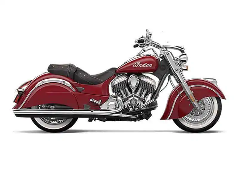
Indian Motorcycle Company (Indian) is recalling certain 2014 Chief and Chieftain motorcycles. Due to a problem within the Vehicle Control Module (VCM), all of the front lights, including the headlight, may go out while riding.
Remedy
The remedy for this recall is still under development. Owners will be informed of the safety risk beginning in June 2019. Owners will receive a second notice when the remedy becomes available. Owners may contact Indian customer service at 1-877-204-3697. Indian’s number for this recall is I-19-02.
Notes
Owners may also contact the National Highway Traffic Safety Administration Vehicle Safety Hotline at 1-888-327-4236 (TTY 1-800-424-9153), or go to www.safercar.gov.
Check for Indian Motorcycle Recalls
IMPORTANT SAFETY RECALL
This notice applies to your vehicle
Recall Campaign: 19V339
Subject: 2014 Indian Motorcycle (111 c.i.)
Forward Lighting
PLEASE READ IMMEDIATELY
VIN I-19-02
FIRST NAME LAST NAME
ADDRESS
CITY, ST ZIP
Dear Indian Motorcycle Owner:
This notice is sent to you in accordance with the requirements of the National Traffic and Motor Vehicle Safety Act. Indian Motorcycle has decided that a defect which relates to motor vehicle safety exists in some 2014 Indian Motorcycles (111 c.i.). Our records indicate you have purchased a potentially affected vehicle.
The reason for this recall:
Indian Motorcycle has identified a potential concern with the forward lighting circuit on 2014 Indian Motorcycles (111 c.i.). In some cases, riders have experienced an unexpected loss of forward lighting while riding (headlight / fog lights). Loss of forward lighting can reduce visibility, which may increase the risk of a crash.
What Indian Motorcycle and your dealer will do:
Indian Motorcycle is currently evaluating a remedy to this concern which is targeted to be available in the Fall of 2019.
Once the final repair plan is available at dealers, Indian Motorcycle will send another letter with additional instructions.
Once available, the remedy will be performed free of charge.
If you have any concerns with the forward lighting on your vehicle prior to the solution becoming available, please contact your authorized dealer for additional information.
What you should do:
Power up the motorcycle and confirm that the forward lighting is functioning properly. If the forward lighting fails to perform as intended or if you have any concerns with the forward lighting, contact your authorized Indian Motorcycle dealer and schedule an appointment to have your motorcycle inspected. If the forward lighting fails to perform as intended, or you do not feel safe riding your motorcycle, work with your Indian Motorcycle dealer to arrange transportation. Do not attempt any repairs yourself. Repairs must be done by an authorized Indian Motorcycle dealer.
If you have questions or if you need more information:
While your Indian Motorcycle dealer is in the best position to answer your questions, if you have any questions that your dealer cannot address, or if you need assistance finding an Indian Motorcycle dealer, please visit our website at https://www.indianmotorcycle.com or contact our Indian Motorcycle Customer Connections Department by calling 1-877204-3697.
If you believe that the dealer or Indian Motorcycle has failed or is unable to remedy the defect within a reasonable time, you may submit a complaint to the Administrator, National Highway Traffic Safety Administration, 1200 New Jersey Avenue S.E., Washington, D.C. 20590, or call the toll free Vehicle Safety Hot Line at 1-888-327-4236 (TTY: 1-800-424-9153), or go to https://www.safercar.gov.
This notice was mailed to you according to our most current registration information. If you no longer own your Indian Motorcycle, please contact your local Indian Motorcycle dealer to have the ownership information changed. The Indian Motorcycle Consumer Service Department cannot change ownership information without identification. Federal law requires that any vehicle lessor receiving this notice must forward a copy of this notice to the lessee within 10 days.
Please accept our apologies for any inconvenience this may cause you. Your safety and continued satisfaction with your Indian Motorcycle is our primary concern. Thank you for your prompt attention to this matter.
Sincerely,
Indian Motorcycle Company
2 Affected Products
Vehicles
| MAKE | MODEL | YEAR |
| INDIAN | CHIEF CLASSIC | 2014 |
| INDIAN | CHIEFTAIN | 2014 |
5 Associated Documents
Defect Notice 573 Report
RCLRPT-19V339-8085.PDF 213.393KB
 Loading...
Recall Acknowledgement
RCAK-19V339-5945.pdf 244.787KB
Loading...
ISSUED Interim Owner Notification Letter(Part 577)
RIONL-19V339-3352.pdf 604.305KB
Loading...
Remedy Instructions and TSB
RCRIT-19V339-5437.pdf 12910.481KB
Loading...
Remedy Instructions and TSB
RCRIT-19V339-8948.pdf 11252.357KB
Loading...
Latest Recalls Documents
For the Latest and Most Recent Recalls Information Visit the link below…
https://www-odi.nhtsa.dot.gov/acms/cs/documentList.xhtml?docId=19V339&docType=RCL
- Perfect Bulb Replacement: If one bulb burns out, the other isn't far behind. Replace your H11 XtraVision Halogen bulbs in pairs for optimum performance.
- Super Bright & Easy to Install: XtraVision bulbs have an enhanced downroad visibility with no added glare.
- DIY Fix for High Quality Performance: XtraVision bulbs have a robust filament design and proprietary gas mixture that can be driven for superior performance in many vehicles.
- Durable High Beam for Maximum Visibility: XtraVision bulbs are designed and manufactured to improve your driving situation while providing maximum durability.
- The Sylvania Standard Of Quality: With over 100 years in business, Sylvania is the world leader in automotive lighting for Original Equipment Manufacturers (OEMs) and the aftermarket.

- 【Compact & Easy installation】 H11 powersports light bulbs almost 1:1 mini design is the same as halogen, no external driver and wire required, real plug and play.
- 【Built-in Cooling Fan】H11 ATV/UTV LED bulbs built in 12,000RPM high-speed cooling fan to provide super cooling ability, which ensures over 50,000 hours of continuous lighting and stable operation.
- 【600% Brighter Than Halogen】Top Automotive-Grade Powersports LED chips, providing up to 16000LM brightness, 60W per set, 6000k cool white, providing you with better visibility and improving your safety when driving at night.
- 【99% Vehicle Compatible】Built-in smart IC driver and high wattage near stock bulbs, make H11 powersports LED bulbs and fog bulbs better compatible with 99% of vehicle systems.
- 【Note】The filter system may not be 100% accurate, please check your owner's manual or the part number on your original bulbs to confirm the bulb size.

- Get up to 30% more vision on the road compared to a standard minimum legal requirements in low beam headlamp test results
- Choose Philips Vision headlights for increased comfort and safety
- Original equipment quality seal for the most reliable performance
- All Philips upgrade headlights are DOT compliant
- Headlight bulbs by Philips, for over 100 years we have been continuously innovating automotive lighting
- Get up to 60% more vision on the road compared to a standard minimum legal requirements in low beam headlamp test results
- Choose Philips VisionPlus headlights for superior quality with enhanced visibility. Base: PGJ19-2
- Original equipment quality seal for the most reliable performance
- All Philips upgrade headlights are DOT compliant
- Headlight bulbs by Philips, for over 100 years we have been continuously innovating automotive lighting

- 【600% Brighter Than Halogen】- Top Automotive-Grade LED chips with 24000LM per pair, 6500K cool white. Super focused beam pattern design provides wider and farther lighting range which is 6 times brighter than your original halogen bulb.
- 【Over 5,0000 Hours Lifespan】 - With whole aviation aluminum body, unique hollow-carved heat sink design and 1,2000RPM turbo cool fan, our 9012 LED bulbs provide super cooling ability, which ensures a longer lifespan up to 5,0000 hours.
- 【10 Minutes Easy Installation】- Almost 1:1 mini design same as halogen, our 9012 light bulbs perfectly fit into your housing and factory sockets without any modification, just plug and play.
- 【CAN bus-Ready for 98% Vehicles】 - Our 9012 LED bulbs and fog bulbs work with 98% of vehicle's computer system without error, while some sensitive models may require additional CAN bus decoder to be installed.
- 【NOTE】- The filter system may not be 100% accurate or up to date, please check your owner's manual or the part number on your original bulbs to confirm the bulb size. Refer to "how to pick the right bulb size" in our Product Description. Our bulbs can be used for powersports ATV/UTV or fog lights. Please let FAHREN know if you can’t figure it out or need any help.

- 【Better Visibility】RCJ H11 led bulb uses a double-sided CSP LED chip, providing up to 16000 lumens of brightness and 6000K whiter and clearer visuals. Allows you to see farther and wider the night driving, ensuring safer night driving.
- 【Ideal Beam Pattern】The H11 fog light features the same 1:1 MINI design as the halogen lamps, the refraction-focusing design ensures excellent beam coverage directly in front of the vehicle. Provides wider-angle and longer-distance light on the road without dazzling oncoming vehicles, with clear demarcation lines.
- 【Plug and play, easy installation】LED bulbs feature an in-line wireless design, no external drives or connectors required, built-in drivers and fans take up less housing space, plug and play like halogen bulbs, no tools or modifications required.
- 【Over 50,000 hours of service life】RCJ led bulbs are made of top aviation aluminum material, built-in cold-pressed aluminum heat sink and a 12,000RPM high-speed cooling fan, which can effectively take away the heat generated by the LED chip, ensuring a lifespan of up to 50000 hours and less number of replacements.
- 【Compatible with 99% of Vehicles】RCJ fog lights are compatible with 99% of vehicle systems, but some sensitive models may still require a CANBUS decoder. NOTE: The filtering system on Amazon is not 100% accurate. If you're not sure which size fits your vehicle, check your owner's manual or the part number on the original bulb to confirm the bulb size.

- Original Equipment Quality Seal For The Most Reliable Performance
- Always Replace In Pairs To Ensure A Symmetric Light Beam From Both Bulbs On The Road. Headlights Dim Over Time
- Headlight Bulbs By Philips, For Over 100 Years We Have Been Continuously Innovating Automotive Lighting
- When Installing A New Bulb, Never Touch The Glass. Either Use Gloves Or Paper Towel When Handling
- Significantly whiter light to improve comfort and safety

- 【600% Brighter than Stock Bulbs】: OXILAM 9005 9006 LED bulbs adopt the latest 2024 LED chip technology, providing 40000 lumens of light output per set, 6 times brighter than halogen bulbs. These 6500K cool white lights provide clear vision, enhancing nighttime road visibility for safe driving on dim and remote roads. It is an excellent choice for upgrading front bulbs, fog lights, high lamps and low lamp. (A set includes 2 9005 LED bulbs and 2 9006 LED bulbs)
- 【Better Driving Experience】: The OXILAM 9005 and 9006 led light bulbs are in the same position as the original halogen filament, with 1:1 size pattern. 16 high-power chips get a farther and wider vision, avoiding accidents with animals crossing the road at night. OXILAM Led light bulbs make driving through rural areas and deserted highways easy and safe.
- 【Real 1:1 Size Makes 100% Fit】: The OXILAM 9005 led bulbs are designed in the same 1:1 size as the stock bulb, no external driver, no huge bulb base. No need to modify the dust cover compared to other LED bulbs. OXILAM 9006 led bulbs have a direct plug-in design, which supports plug-and-play, quick installation within 5 minutes, 100% installation problem free.
- 【99% Vehicle Compatibility】: The OXILAM 9005 9006 combo led bulbs kit has a built-in intelligent IC driver, no radio interference, CANBUS ready for 99% vehicle systems. Say goodbye to suddenly shut off, annoying flickering and unstopped dash errors when driving. For 1% sensitive vehicles, we can send an additional decoder to help solve the issue.
- 【Triple Cooling for 50,000 Hours of Lifespan】: The OXILAM led bulbs adopt a high-quality aviation aluminum body that ensures effective heat dissipation without any risk of the light body breaking apart. The led light bulbs also include superior a copper baseboard and a 12000rpm silent turbo fan that effectively dissipates heat, ensuring a lifespan of 50,000 hours.
- Lights Dim Over Time, Replace In Pairs: Your lights are a pair, one is never turned on without the other. If one bulb burns out, the other isn't far behind. Replace your H13 XtraVision Halogen bulbs in pairs for optimum performance.
- More Downroad Visibility: XtraVision bulbs have an enhanced downroad visibility with no added glare.
- Reliable Design For Optimal Performance: XtraVision bulbs have a robust filament design and propriety gas mixture that can be driven for superior performance.
- Manufactured To Be Durable: XtraVision bulbs are designed and manufactured to improve your driving situation while providing maximum durability.
- The Sylvania Standard Of Quality: With over 100 years in business, Sylvania is the world leader in automotive lighting for Original Equipment Manufacturers (OEMs) and the aftermarket.
- Get up to 60% more vision on the road compared to a standard minimum legal requirements in low beam headlamp test results
- Choose Philips VisionPlus headlights for superior quality with enhanced visibility
- Original equipment quality seal for the most reliable performance
- All Philips upgrade headlights are DOT compliant
- Headlight bulbs by Philips, for over 100 years we have been continuously innovating automotive lighting
Last update on 2024-04-12 / Affiliate links / Images from Amazon Product Advertising API
This product presentation was made with AAWP plugin.
SEOCONTENT-START
The information contained within this document is confidential and protected by U.S. and international copyright laws, and is the property of Polaris Inc. This document is provided for the sole use of authorized Polaris dealers and distributors. This document is not to be distributed, duplicated, or copied, digitally or otherwise, without the written consent of Polaris Inc. I-19-02 (R03) © 2020 Polaris Inc. Page 1 of 7 I-19-02-B VCM REPLACEMENT AND PIN REPAIR KIT CONTENTS (P/N 2208321) REF PART DESCRIPTION PART NUMBER QTY q Vehicle Control Module (VCM) 4016189 1 w Heat Shrink Tube 2410766 1 e VCM Connector Assembly 2415294 1 TOOLS REQUIRED • 5 mm Allen Wrench • 6 mm Allen Wrench • In-lb Torque Wrench • Small Flat Bladed Screwdriver • Wire Stripper • Electrical Tape • Heat Gun • Terminal Removal Tool PF-52576 The information contained within this document is confidential and protected by U.S. and international copyright laws, and is the property of Polaris Inc. This document is provided for the sole use of authorized Polaris dealers and distributors. This document is not to be distributed, duplicated, or copied, digitally or otherwise, without the written consent of Polaris Inc. I-19-02 (R03) © 2020 Polaris Inc. Page 2 of 7 I-19-02-B VEHICLE CONTROL MODULE (VCM) & CONNECTOR REPLACEMENT VCM REMOVAL 1. Connect to motorcycle using Digital Wrench and record Master PIN and key fob number(s). IMPORTANT Make sure you accurately record BOTH the Master PIN and key fob number(s) before disconnecting the VCM. 2. Using a 5 mm Allen Wrench, remove the fastener e securing the Vehicle Control Module (VCM) mounting plate to the top of the battery box. CAUTION Do not allow the VCM to contact the positive (B+) terminal or damage to the VCM will result. 3. Lift the VCM mounting plate enough to access the negative battery terminal. 4. Using a Phillips screwdriver, remove the negative battery cable fastener, and secure the ground cables away from the terminal. 5. Disconnect the three multi-plugs from the VCM. 6. Move the VCM forward to disengage the retaining posts that secure the front of the VCM to the battery box and remove. Return the VCM to Indian Motorcycle. The information contained within this document is confidential and protected by U.S. and international copyright laws, and is the property of Polaris Inc. This document is provided for the sole use of authorized Polaris dealers and distributors. This document is not to be distributed, duplicated, or copied, digitally or otherwise, without the written consent of Polaris Inc. I-19-02 (R03) © 2020 Polaris Inc. Page 3 of 7 REPLACING THE VCM CONNECTOR 1. Locate the two electrical tape pieces on the middle VCM connector. Peel and remove the electrical tape closest to the connector of the VCM harness as shown. 2. Raise the white terminal lock into service mode by inserting a small flat bladed screwdriver through the access windows in both sides of the outer connector body. Pry gently upwards to push up both sides of the white terminal lock. 3. The white terminal lock will come up 3.8 mm and stop due to retaining tabs on the sides. There may be an audible click noted. IMPORTANT Do not remove the white terminal lock from the outer connector body. CAUTION If the white terminal lock is removed, the terminals can fall out of position. Avoid excessive movement of the harness/connector to ensure the terminals stay in their locations. 4. Using Terminal Removal Tool PF-52576 remove the Red Wire (Pin 11) from the connector block. Insert PF-52576 into the small, round release slot of the associated terminal(s) until it releases the terminal retainer. Gently pull the wire out of the connector. The information contained within this document is confidential and protected by U.S. and international copyright laws, and is the property of Polaris Inc. This document is provided for the sole use of authorized Polaris dealers and distributors. This document is not to be distributed, duplicated, or copied, digitally or otherwise, without the written consent of Polaris Inc. I-19-02 (R03) © 2020 Polaris Inc. Page 4 of 7 5. Measure and cut approximately two inches from the end of the Red Wire (Pin 11). Discard the terminal end of the wire. MEASUREMENT 2 inches 6. Using a Wire Stripper, remove approximately 1/2 inch of insulation from Red Wire (Pin 11) and the new terminal wire. 7. Install the solder tube onto the wires. 8. Using a Heat Gun, apply heat to the solder tube until the tube is properly secured around both ends of the wire as shown. 9. Insert the Terminal Removal Tool PF-52576 into the small, round release slot of the associated terminal(s) until it releases the terminal retainer. Gently pull the wire out of the connector. The information contained within this document is confidential and protected by U.S. and international copyright laws, and is the property of Polaris Inc. This document is provided for the sole use of authorized Polaris dealers and distributors. This document is not to be distributed, duplicated, or copied, digitally or otherwise, without the written consent of Polaris Inc. I-19-02 (R03) © 2020 Polaris Inc. Page 5 of 7 10. Remove and replace the wires from the old connector block to the new one. Refer to the CONNECTOR BLOCK PIN LAYOUT image and table when replacing the wires. After replacing each wire, listen for an audible click and gently pull on the wire to make sure it is secure. NOTICE For best results, extract and replace pins from the connector block one at a time while transferring them to the new connector block. Leaving the Terminal Removal Tool PF-52576 in the place of the pin you are replacing may also help to avoid confusion about what terminal the wire came out of. IMPORTANT The bottom end of the connector pin has a terminal retainer tab that allows the pin to clip into the terminal block. This raised tab must ALWAYS face the outside of the terminal block when installing the wire into the new terminal block. NOTICE The white terminal lock must stay up at the service position for all wire replacement. If you are having problems with the wires not coming out of the terminal block, double check that the terminal lock is in the service position. STOP! Once all of the pins have been transferred to the new connector block, place a white piece of paper between the electrical wires as shown. Take a picture of both sides of the connector and wires and submit the photos to the ASK Polaris case. 11. Press down on the white terminal lock to release it from service mode. 12. Cut a 3 inch strip of electrical tape and wrap around the harness wires as shown. The information contained within this document is confidential and protected by U.S. and international copyright laws, and is the property of Polaris Inc. This document is provided for the sole use of authorized Polaris dealers and distributors. This document is not to be distributed, duplicated, or copied, digitally or otherwise, without the written consent of Polaris Inc. I-19-02 (R03) © 2020 Polaris Inc. Page 6 of 7 CONNECTOR BLOCK PIN LAYOUT **Viewed from the back-side of the connector where the wires enter the connector.** PIN COLOR WIRE q YELLOW w GREEN e PINK r GREY t RED y GREY/BLUE u GREEN i ORANGE/WHITE o RED/WHITE a NA s RED d GREEN/RED f GREEN g BROWN h NA j NA k BLACK l NA 1( NA 2) RED The information contained within this document is confidential and protected by U.S. and international copyright laws, and is the property of Polaris Inc. This document is provided for the sole use of authorized Polaris dealers and distributors. This document is not to be distributed, duplicated, or copied, digitally or otherwise, without the written consent of Polaris Inc. I-19-02 (R03) © 2020 Polaris Inc. Page 7 of 7 VCM INSTALLATION 1. Connect the three connectors to the NEW VCM. Listen for an audible click. 2. Connect the negative battery cable and torque fastener to specification. TORQUE Battery Terminal Fastener: 40 in-lbs (5 N·m) 3. Engage the VCM bracket posts fully into the battery box slots. CAUTION Do not allow the VCM to contact the positive (B+) terminal or damage to the VCM will result. 4. Install the fastener e securing the Vehicle Control Module (VCM) mounting plate to the top of the battery box. Torque fastener to specification. TORQUE VCM Bracket Fastener: 84 in-lbs (9 N·m) 5. Connect to motorcycle using Digital Wrench and rewrite the key fob number(s) previously recorded. IMPORTANT Make sure Digital Wrench at the most current version 6. Chose the “key fob maintenance” screen and power the motorcycle off and then back on. If the fob was programmed properly, the MASTER PIN should now show when opening “key fob maintenance” again. 7. Perform the Vehicle Controller update. NOTICE If a customer had previously entered a personal security system pin, it will need to be programmed at this point. Please see Team Tip I-13-09-01 for instructions. 8. Test ride the motorcycle to ensure proper operation. 9. File a claim for I-19-02-B
**************************************************************************************************************
The information contained within this document is confidential and protected by U.S. and international copyright laws, and is the property of Polaris Inc. This document is provided for the sole use of authorized Polaris dealers and distributors. This document is not to be distributed, duplicated, or copied, digitally or otherwise, without the written consent of Polaris Inc. I-19-02 (R03) © 2020 Polaris Inc. Page 1 of 12 SAFETY BULLETIN IND Release Date: May 07, 2019 Communication #: I-19-02-A/B Model Year(s): 2014 — Confidential and Proprietary — VERSION: R03 (March 03, 2020) ** Changed from STOP SALE to SAFETY BULLETIN** IMPORTANT STOP SALE SAFETY NOTICE! Stop selling affected vehicles immediately until the repair procedure has been completed on affected units at your dealership. Federal law prohibits the sale of products subject to a recall. Selling such products could subject the seller to substantial penalties. IMPORTANT If you are working with a printed copy, please verify you have the most current version of this document. SUBJECT: 2014 INDIAN MOTORCYCLE – FORWARD LIGHTING PURPOSE Indian Motorcycle has decided that an electrical defect may exist in 2014 Indian Motorcycles (111 c.i.), resulting in the unexpected loss of forward lighting. This defect may also cause thermal damage to the Vehicle Control Module (VCM) and Pin 11 of the center VCM connector. Indian Motorcycle has released this bulletin with instructions to inspect the VCM connector for damage & reflash the VCM. If damage to the connector is present, you will need to start an ASK Polaris case for repair instructions and warranty claim processing. AFFECTED MODELS MODEL YEAR MODELS VEHICLE IDENTIFICATION NUMBER RANGE 2014 Chief Classic Reference Unit Inquiry on the dealer website or the Service Communications list on the STOP site to lookup affected VINs. Chief Vintage Chieftain IMPORTANT Vehicles that had ISA-19-02 performed as an interim solution are still required to have this updated repair solution performed. Reference Unit Inquiry to determine if a VIN is affected. The information contained within this document is confidential and protected by U.S. and international copyright laws, and is the property of Polaris Inc. This document is provided for the sole use of authorized Polaris dealers and distributors. This document is not to be distributed, duplicated, or copied, digitally or otherwise, without the written consent of Polaris Inc. I-19-02 (R03) © 2020 Polaris Inc. Page 2 of 12 CUSTOMER NOTIFICATION Dealers are required to review their sales records and make arrangements with customers for Bulletin completion. In addition to consumer units, dealers are required to correct any affected units in their inventory. Indian Motorcycle will be mailing a notification letter to consumers affected by this Bulletin. WARRANTY CLAIM PARTS INFORMATION Bulletin parts are excluded from the standard RMA policy and cannot be returned. An Initial Recommended Order Quantity has not been provided for this bulletin. Service kit 2208321 will be allocated upon Indian Technical Service review and approval of ASK Polaris case. For more details, refer to University of Polaris training course “Polaris Item Availability and Daily Ordering” and click on “Bulletin Ordering Training”. VCM CONNECTOR INSPECTION & VCM REFLASH Bulletin # I-19-02-A Claim Type SB (Service Bulletin) Labor Allowance 0.6 hours (36 minutes) Part Number / Description 0000541 (QTY 1) Bulletin Misc Labor Parts Availability NA University of Polaris Training Required Yes1 1Polaris requires one person from a dealership to be certified before parts ordering may occur and two people from a dealership to be certified before warranty claims may be processed. NOTICE Training required for this bulletin is carried forward from the original release in May, 2019. If your dealership personal is still certified, you will NOT need to retake the training VCM & CONNECTOR REPLACEMENT Bulletin # I-19-02-B Claim Type SB (Service Bulletin) Labor Allowance 1.0 hours (60 minutes) Part Number / Description Additional parts and labor required to complete I-19-02-B to be authorized through an ASK Polaris case. Parts Availability Available to order when directed by ASK Polaris ACCESSORY LABOR Polaris will cover labor for the removal and installation of accessories required to complete the bulletin work. Follow the steps below to obtain reimbursement. The information contained within this document is confidential and protected by U.S. and international copyright laws, and is the property of Polaris Inc. This document is provided for the sole use of authorized Polaris dealers and distributors. This document is not to be distributed, duplicated, or copied, digitally or otherwise, without the written consent of Polaris Inc. I-19-02 (R03) © 2020 Polaris Inc. Page 3 of 12 1. Start a new Ask Polaris Case, Service &Warranty Question > Authorization Request: In Warranty or Polaris ESC or Authorization Request: Out of Warranty/Goodwill. 2. Enter your contact information and VIN, along with miles and hours into the applicable fields. 3. Enter Indian Motorcycle® I-19-02, and I-19-02 in the CONCERN and CAUSE fields. In the CORRECTION field, enter “ACCESSORY REMOVAL AND INSTALLATION”. 4. Enter warranty fail codes 127/277/132. 5. Add part 0000541, quantity 1. 6. Attach photos of the vehicle and accessories sufficient to support the labor time requested. 7. Submit the case to Polaris. COVERAGE PERIOD Coverage began on March 3rd, 2020. This bulletin has no expiration date. PARTS RETURN / DISPOSAL INFORMATION Under no circumstances shall the parts removed be re-used, sold, or re-purposed for another application. It is your dealership / distributor’s responsibility to make sure every part replaced (related to this communication) is taken out of circulation and disposed of properly or returned to Polaris (if required). SPECIAL TOOLS • US and Canada Dealers: The special tool outlined in Part B of this Bulletin (PF-52576) was direct-shipped to dealers in February of 2018 for use with I-18-01. If additional or replacement tools are needed, they can be ordered through Bosch Automotive Service Solutions, by phone at 1-800-345–2233 or on-line via your dealer website at https:// polaris.service-solutions.com/. • International Dealers: The special tool outlined in this Bulletin (PF-52576) must be ordered through the Bosch Service Solutions website. File a Part Stock warranty claim for tool reimbursement. The information contained within this document is confidential and protected by U.S. and international copyright laws, and is the property of Polaris Inc. This document is provided for the sole use of authorized Polaris dealers and distributors. This document is not to be distributed, duplicated, or copied, digitally or otherwise, without the written consent of Polaris Inc. I-19-02 (R03) © 2020 Polaris Inc. Page 4 of 12 I-19-02-A VCM PIN INSPECTION & REFLASH TOOLS REQUIRED • Digital Wrench w/ SmartLink or MultiLink XP • 5 mm Allen Wrench • 6 mm Allen Wrench • In-lb Torque Wrench • Phillips Screwdriver The information contained within this document is confidential and protected by U.S. and international copyright laws, and is the property of Polaris Inc. This document is provided for the sole use of authorized Polaris dealers and distributors. This document is not to be distributed, duplicated, or copied, digitally or otherwise, without the written consent of Polaris Inc. I-19-02 (R03) © 2020 Polaris Inc. Page 5 of 12 I-19-02-A VEHICLE CONTROL MODULE (VCM) CONNECTOR PIN 11 INSPECTION & VCM REFLASH VCM CONNECTOR PIN 11 INSPECTION IMPORTANT In the event the following inspection does reveal damage to Pin 11 of the center VCM connector (harness side), start an ASK Polaris case for further instruction as outlined in the I-19-02-B section of this document. 1. Park the motorcycle on a lift table with the wheel clamped in a wheel vise. 2. Turn the ignition off. 3. Remove Accessory Trunk, if applicable. • Remove the left and right saddlebags and remove the trunk lock fastener t from each trunk latch. • Disconnect the trunk harness multi-plug r. • Lift the trunk latches e to unlock the trunk from the mount. • Lift up on the rear of the trunk rand slide rearward t to release the trunk from the motorcycle. 4. Pull carefully on the side panels to release the retaining posts from the in-frame grommets. The information contained within this document is confidential and protected by U.S. and international copyright laws, and is the property of Polaris Inc. This document is provided for the sole use of authorized Polaris dealers and distributors. This document is not to be distributed, duplicated, or copied, digitally or otherwise, without the written consent of Polaris Inc. I-19-02 (R03) © 2020 Polaris Inc. Page 6 of 12 5. Using a 5 mm Allen Wrench, remove the rear seat fastener w. 6. Using a 6 mm Allen Wrench, remove the two fasteners q securing the seat to the frame. 7. Lift the rear of the seat and pull rearward to disengage the front retaining arms from the bracket behind the fuel tank. 8. Place the seat upside down on a smooth, clean surface. 9. Find the VCM located on top of the battery box. 10. Disconnect the center connector on the VCM. Locate Pin 11 of the VCM1 (center) connector and check for any discoloration. IMPORTANT Pay special attention to the white terminal lock plate during inspection. If damage is present, a dark halo will be present around pin 11 of the VCM connector. Refer to the pictures below for examples. The information contained within this document is confidential and protected by U.S. and international copyright laws, and is the property of Polaris Inc. This document is provided for the sole use of authorized Polaris dealers and distributors. This document is not to be distributed, duplicated, or copied, digitally or otherwise, without the written consent of Polaris Inc. I-19-02 (R03) © 2020 Polaris Inc. Page 7 of 12 DAMAGE IS NOT PRESENT DAMAGE IS PRESENT VCM connector, pin 11 VCM connector, pin 11 Damage = Any sign of heat or thermal damage in or around pin 11 of the center VCM connector (e.g. the dark halo shown in the right image above). STOP! • If damage IS present, take pictures of the damage and proceed to I-19-02-B. US/CAN: Submit an Ask Polaris Service & Warranty Question> All Vehicle Diagnostic case. INT’L: Contact your Country Service Department. • If damage is NOT present, proceed to step 11 to complete I-19-02-A. The information contained within this document is confidential and protected by U.S. and international copyright laws, and is the property of Polaris Inc. This document is provided for the sole use of authorized Polaris dealers and distributors. This document is not to be distributed, duplicated, or copied, digitally or otherwise, without the written consent of Polaris Inc. I-19-02 (R03) © 2020 Polaris Inc. Page 8 of 12 11. Connect the VCM connector back to the VCM. Listen for an audible click. 12. Install the seat by sliding the seat forward to engage the retaining arms on the frame into the seat. 13. Loosely install both side seat fasteners q. 14. Loosely install the rear seat fastener w. 15. Torque all three seat fasteners to specification. TORQUE Seat Fastener: 84 in-lbs (9 N·m) 16. Install the side panels by aligning the side panel pins with the in-frame grommets and push inward to engage. 17. Install Accessory Trunk, if applicable. CAUTION Use care when installing the trunk assembly so that no electrical wires / connectors get pinched. The information contained within this document is confidential and protected by U.S. and international copyright laws, and is the property of Polaris Inc. This document is provided for the sole use of authorized Polaris dealers and distributors. This document is not to be distributed, duplicated, or copied, digitally or otherwise, without the written consent of Polaris Inc. I-19-02 (R03) © 2020 Polaris Inc. Page 9 of 12 • Lift the flap at the rear of the passenger seat pad to access the vehicle side of the trunk harness connector and lay harness on fender. • Slide the trunk forward q onto the mounting bracket and lower w the rear of the trunk until fully seated. • Push the trunk locking levers e down until fully seated and the trunk is held securely in place. • Reconnect the trunk harness connector r. • If applicable, install the mounting fasteners t into left and right locking levers. • Install saddlebags, if equipped. The information contained within this document is confidential and protected by U.S. and international copyright laws, and is the property of Polaris Inc. This document is provided for the sole use of authorized Polaris dealers and distributors. This document is not to be distributed, duplicated, or copied, digitally or otherwise, without the written consent of Polaris Inc. I-19-02 (R03) © 2020 Polaris Inc. Page 10 of 12 VCM REFLASH 1. Verify that Digital Wrench version 4.1 Update 2/26/20 or later has been installed on your PC or laptop and proceed to step 6. If you do not have Version 4.1 – Update 2/26/20 or later installed, you must first download it before proceeding with the reflash. NOTICE If you do not have Digital Wrench installed on your computer, you must first download the Digital Wrench Base Version Installer (STEP 2). 2. To download Digital Wrench Base Version, go to your dealer homepage and select Digital Wrench Base Version Installer from the Service and Warranty dropdown menu and download. NOTICE International Subsidiaries and Distributors use the Digital Wrench Subscriptions link to purchase and update your digital wrench software. 3. Once the Base Version is installed, go to your dealer homepage and select Digital Wrench Updates from the Service and Warranty dropdown menu. 4. Click on Digital Wrench Version 4.1 Updates. 5. Download and install Digital Wrench Version 4.1 update 2/26/20 or higher. 6. Connect SmartLink / MultiLink XP cables to PC and vehicle. 7. Open the Digital Wrench program. 8. Select the model year, product line, and vehicle description by selecting the “Change Vehicle Type” icon . 9. Select the Special Test Tab q. 10. Select Vehicle Controller Update w. The information contained within this document is confidential and protected by U.S. and international copyright laws, and is the property of Polaris Inc. This document is provided for the sole use of authorized Polaris dealers and distributors. This document is not to be distributed, duplicated, or copied, digitally or otherwise, without the written consent of Polaris Inc. I-19-02 (R03) © 2020 Polaris Inc. Page 11 of 12 IMPORTANT Use of Engine Controller Reprogramming instead of Vehicle Controllers Update will result in loss of stage calibration. NOTICE Digital Wrench will automatically identify current software levels and determine which modules require software updates. IMPORTANT Make sure the vehicle battery is fully charged or connected to a battery charger before proceeding. STAGE CALIBRATION: If a motorcycle is equipped with an Indian Motorcycle stage calibration, Digital Wrench will identify and maintain the upgraded software calibration if Vehicle Controllers Update is selected. CAUTION The VCM update procedure will take you through TWO separate reprogramming procedures. • Boot Mode • Reflash Application During the reflash process the gauge and all indicators will power down. Each procedure must be completed in sequence or the VCM will not function. 11. Follow the on-screen prompts until all control modules have been updated. 12. Once the flash is complete, hit the continue button and leave Digital Wrench connected and ignition powered ON. Do NOT touch the unit for 35 seconds. 13. Power ignition off and wait 130 Seconds. 14. Check / clear any stored fault codes, disconnect Digital Wrench and test ride the motorcycle. NOTICE Following the VCM reflash, some customers may notice a slight delay in illumination of their fog lights (if equipped) during vehicle use. This is normal and is intended to reduce current flow through the VCM 15. File a claim for I-19-02-A The information contained within this document is confidential and protected by U.S. and international copyright laws, and is the property of Polaris Inc. This document is provided for the sole use of authorized Polaris dealers and distributors. This document is not to be distributed, duplicated, or copied, digitally or otherwise, without the written consent of Polaris Inc. I-19-02 (R03) © 2020 Polaris Inc. Page 12 of 12 I-19-02-B IMPORTANT US/CAN Dealers: Submit an Ask Polaris Service & Warranty Question > Vehicle Diagnostic Question case. INT’L Dealers: Contact your Country Service Department. Submit photos of the dark halo present around VCM pin 11 on the white terminal lock plate and wait for further instructions from Indian Motorcycle Technical Service. Do not allow the machine to be operated until you have repaired the machine as directed by Technical Service. If damage is present at Pin 11, do not file a warranty claim for either I-19-02-A OR I-19-02-B until directed by Indian Motorcycle Technical Service.
**************************************************************************************************************
SEOCONTENT-END