
| “This site contains affiliate links for which OEMDTC may be compensated” |
August 6, 2020 NHTSA CAMPAIGN NUMBER: 20V460000
Flywheel May Break Causing Engine Oil Leak
Leaking oil may drip into the path of the rear tire, increasing the risk of a crash.
NHTSA Campaign Number: 20V460
Manufacturer Ducati North America
Components ELECTRICAL SYSTEM, ENGINE
Potential Number of Units Affected 156
Summary
Ducati North America (Ducati) is recalling certain 2021 Streetfighter V4 and Streetfighter V4 S motorcycles. The generator rotor (flywheel) may break, damaging the generator cover and causing oil leakage from the engine.
Remedy
All affected vehicles are still in dealer inventory. Dealers will inspect the production dates on the generator rotors (flywheels) and replace them, as necessary. The recall began August 12, 2020. Owners may contact Ducati customer service at 1-888-391-5446. Ducati’s number for this recall is SRV-RCL-20-002.
Notes
Owners may also contact the National Highway Traffic Safety Administration Vehicle Safety Hotline at 1-888-327-4236 (TTY 1-800-424-9153), or go to www.safercar.gov.
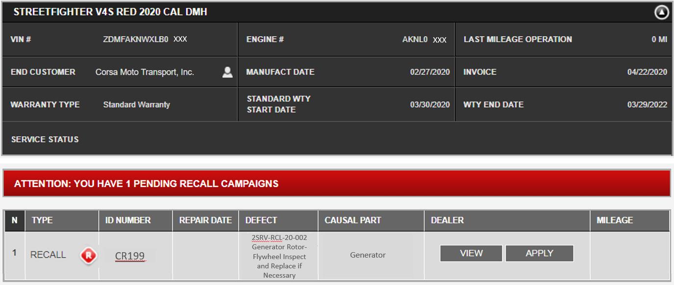
CR199 – Generator Rotor/Flywheel Inspect and Replace if Necessary
Streetfighter V4 STD/S MY 2021 (all Versions)
Recall Bulletin SRV-RCL-20-002
| Date: | August 11, 2020 |
| To: | Dealer Principal, General Manager, Service Manager, North American Dealer Network |
| From: | Richard Kenton, Technical Director Eric Bradley, Technical Training and Publications Manager |
Dear Dealers,
Due to a potential defect in the supplier’s production process of the generator rotor (flywheel), it is necessary to inspect and, if necessary, replace the rotor on a limited production run of both Streetfighter V4 Standard and S models manufactured during the month of July 2020.
While no failures have been reported to Ducati at the time of this publication, there is a remote possibility of the rotor failing, which could damage the generator cover and introduce the risk of oil leakage from the engine.
The motorcycles involved can be used at low engine speeds to allow transport to your workshop for the completion of this service bulletin.
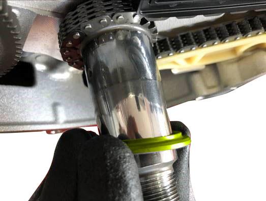
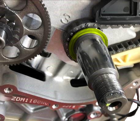
To identify affected units, please reference the batch number which is clearly written on the part. It is necessary to remove the generator cover to see this number (it is not necessary to drain the oil from the engine).
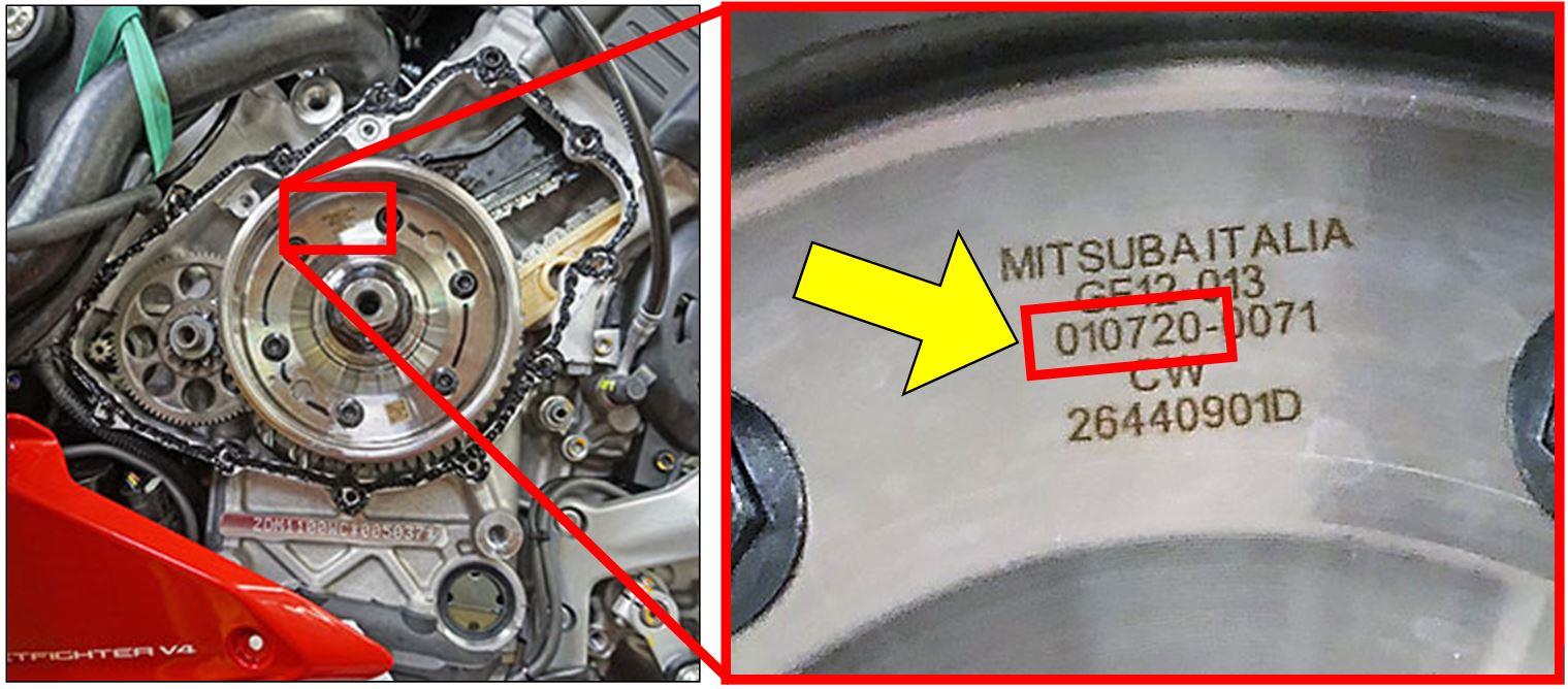
On the affected motorcycles, check the production date on the generator rotor (flywheel) and if one of the 6 production dates relating to potentially defective batches is found on the component, replacement will be necessary. The batches of generator rotors (flywheels) identified as potentially defective are: 280620, 290620, 300620, 010720, 020720, and 030720
Application
You can find the precise list of VIN numbers involved in CR199 on the DCS, in sections:
| VIN HISTORY |  |
It is possible to search by individual frame number. |
| CAMPAIGNS |  |
It is possible to search for all the frame numbers that you received from Ducati North America. |
Customer Impact
All motorcycles in your inventory (to be registered or already registered) and to be delivered to final Customers must be updated during pre-delivery operations and always before delivery to the final Customer. No units have been warranty registered or retailed to end customers at the time of this publication, therefore no owner notification letters are to be issued.
Distribution
The generator rotor/flywheel part no. 26440901D will be sent to your dealer automatically, based upon the volume of potentially affected vehicles your dealer is scheduled to receive. If additional units are required, they must be ordered for each affected frame number.
The required sealant (part no. 942470036) and thread locking compound are common shop supplies in stock for Ducati dealers and do not require any special order, and are produced in packaging sizes sufficient to complete this operation on multiple vehicles.
Warranty Reimbursement Rules
Reimbursement for work associated with this Safety Recall Campaign will be done through the regular warranty claim procedure using the “VIN History” section of the DCS. The warranty claim is pre-filled and is identified as CR199. Two types of operations are provided and described below:
Operation Type 1:
| Description | Spare Parts | Labor | |
| TYPE 1 | Checking production date of generator rotor | No Parts Required | 1h:36min
(16 LU) |
Operation Type 1 is a check and inspect of the affected components when no replacement is necessary, and includes reimbursement for the parts listed for the consumables required and labor for 1h:36min (16 labor units) that includes the time necessary for:
- Vehicle reception
- Remove generator cover and inspection rotor/flywheel
- Reinstall generator cover
- Soft cleaning of the vehicle
Operation Type 2:
| Description | Spare Parts | Labor | |
| TYPE 2 | Checking production date and replacement of generator rotor | Generator Rotor 26440901D | 2h:0min
(20 LU) |
Operation Type 2 includes reimbursement for the parts listed for the operation; 26440901D generator rotor (flywheel), and consumables required; and labor for 2h:0min (20 labor units) that includes the time necessary for:
- Vehicle reception
- Remove generator cover and inspection rotor/flywheel
- If required, Install new rotor/flywheel 26440901D
- Reinstall generator cover
- Soft cleaning of the vehicle
Table of Contents
| Page | |
| Introduction | 1 |
| Application | 2 |
| Customer Impact | 2 |
| Parts Distribution | 2 |
| Warranty Reimbursement Rules | 3 |
| Spare Parts | 4 |
| Service Solution | 5 |
| Operation 1: Inspect Generator Rotor Production Date | 5 |
| Operation 2 Part 1: Generator Rotor Replacement | 8 |
| Operation 2 Part 2: Reinstallation of the Generator Cover | 18 |
| Additional Requirements and Notes | 24 |
Spare Parts
The component required for this update is indicated below:
| Part no. | Description | Photo | Quantity to order (pcs) |
| 26440901D | ROTOR ACG 1308 MITSUBA MAGN. N48UH-GR | 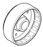 |
1 |
Service Solution
WARNING
To ensure the correct execution of the operation within the provided labor time to carry out the updates, it is necessary to follow the sequence indicated in the following instructions
Operation 1: Inspect Generator Rotor Production Date
NOTE
To inspect and possibly replace the generator rotor it is not necessary to drain oil from the engine, as its level is lower than generator cover lower profile.
- Position the motorcycle on the central paddock stand
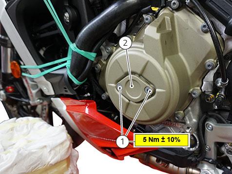
- Loosen the 2 screws (1) and remove the timing inspection cover (2)
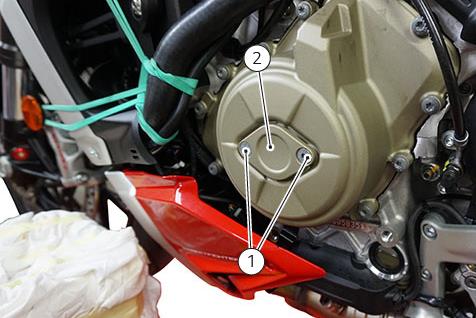
- Loosen and remove the fastening screws (3) and (4) on the generator cover
NOTE
Please note the screws are different between Panigale V4 and Streetfighter V4 models; The Streetfighter V4 model also has a mounting bracket for the left lug.
The quantity and type of screws are as follows:
no. 77942002A) ISO 14579 M6X27
- Panigale V4: 11 screws (part no. 77941992A)ISO 14579 M6X19 + 1 screw (part no. 77942002A) ISO 14579 M6X27
- Streetfighter V4: 9 screws (part no. 77941992A)ISO 14579 M6X19 + 3 screws (part
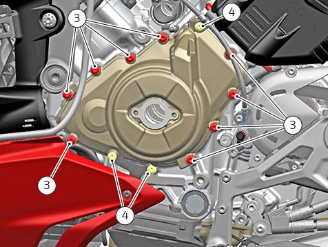
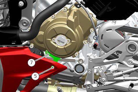
- Loosen and remove the screw (5) securing lug to generator cover. Remove the bracket (7)securing the LH lug to generator cover
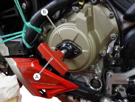
- Place tool (A) part no. 88713.8857 using inspection cover fastening holes. Using tool (A), remove the generator cover (6)
- Check the production date indicated on the generator rotor
| NON-COMPLIANT Generator rotor production dates – TO BE REPLACED | ||
| 280620 | 290620 | 300620 |
| 010720 | 020720 | 030720 |
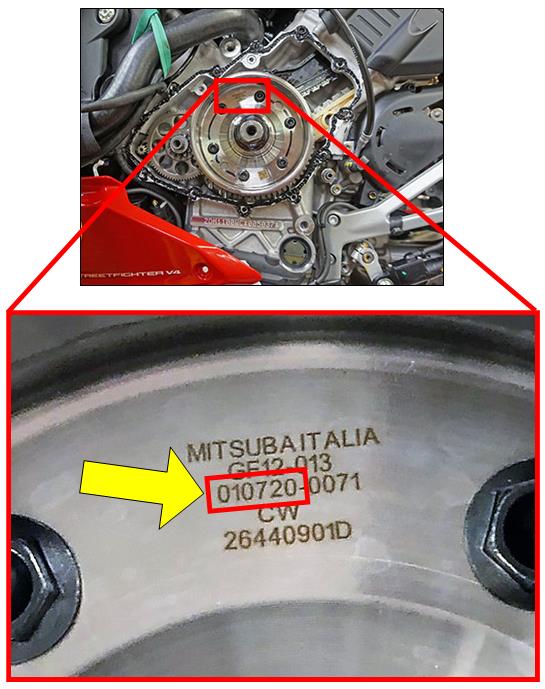
- If the production date is compliant and not included on the provided list, it is NOT necessary to replace the generator rotor (flywheel). Refit the generator cover as described in Operation 2 Part 2: Reinstallation of Generator Cover
- If the production date is NON-compliant as defined on the provided list, it Is necessary to replace the generator rotor, please proceed with Operation 2: Generator Rotor Replacement and Operation 2 Part 2: Reinstallation of Generator Cover
Operation 2 Part 1: Generator Rotor Replacement
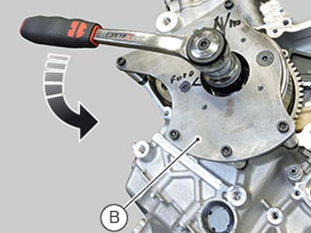
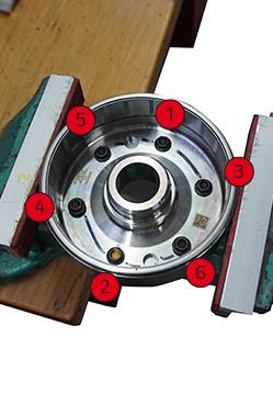
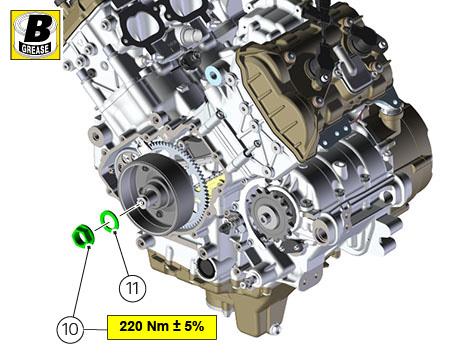
- Place tool (B) for flywheel nut removal part no. 88713.8853 and tighten the 5 screws (8)to 10 Nm

NOTE
Pay attention during alignment of tool (B) in the flywheel. The two holes (9) are not the same, one is bigger than the other. Check the correct insertion
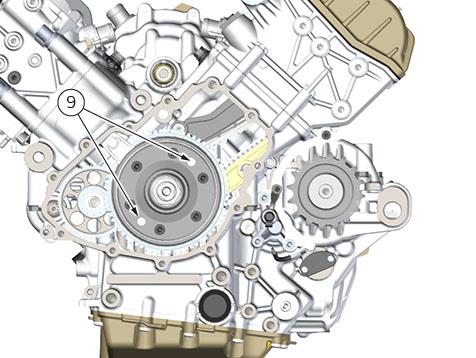
NOTE
From this point on, some of the pictures below show an engine on the bench to offer an improved and clearer view. The removal of the engine from the frame is not necessary to carry out the procedure
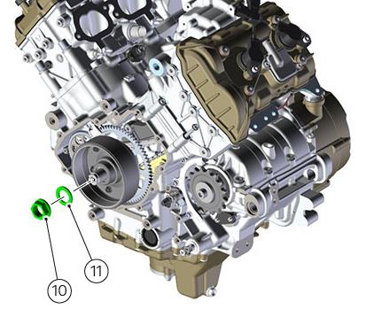
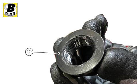
- Loosen the generator rotor nut (10) and collect washer (11)
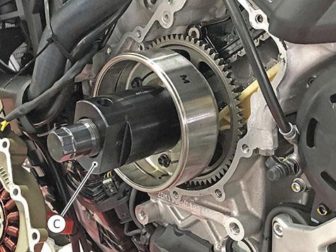
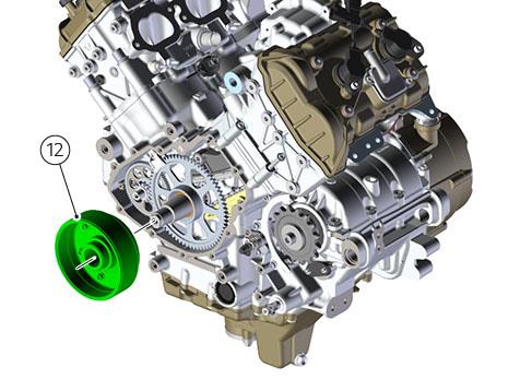
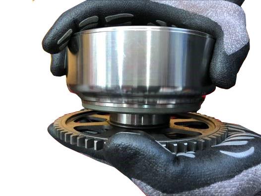
- Install tool (C) magnet flywheel puller part no. 88713.8854.
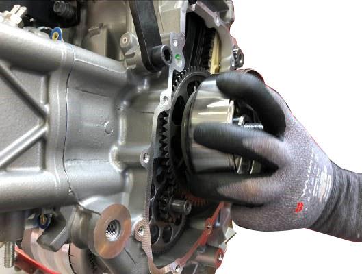
- Loosen and remove the generator rotor assembly (12)
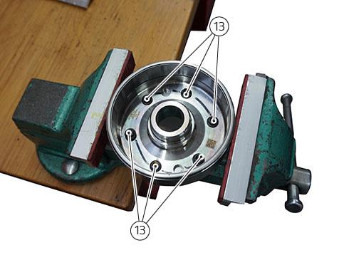
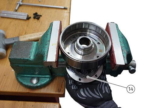
- Place the rotor assembly in a vice with rubber or Teflon protections on the jaws so as not to damage the generator rotor. The vice must not be tightened with excessive force. Loosen and remove the 6 screws (13) securing rotor to flange/starter clutch
WARNING
Assemblies damaged due to excessive torque are not warrantable and are the responsibility of the dealer to correct
NOTE
The 6 screws (13) are installed using Loctite 648. If you find it difficult to unscrew them, heat them first with a hot air gun.
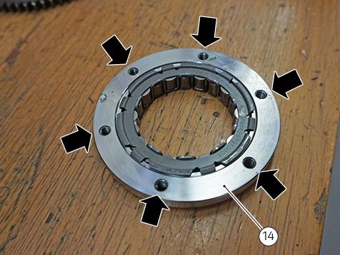
- Using suitable equipment, tap alternately in the two holes shown in the figure, to separate the rotor from the flange/starter clutch (14)
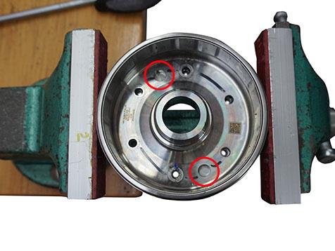
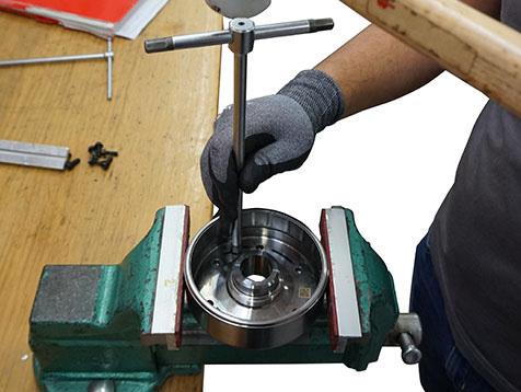
NOTE
During the operation, support the flange/starter clutch (14) so that it does not fall out below. Ask for a colleague’s help if necessary.
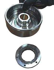
- Prepare the new generator rotor for install
- Thoroughly clean the threads of the flange/starter clutch (14) and remove the previously applied threadlocker
- Thoroughly clean the thread of the 6 screws (13) retaining the flange/starter clutch and remove the previously applied thread locking compound
- Install the flange/starter clutch assembly in the new rotor. Neither the flange nor the starter clutch have a timing position relative to the flywheel, so only pay attention to the side of installation
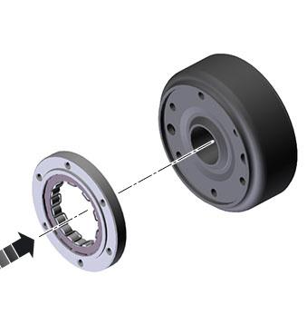
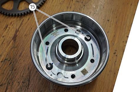
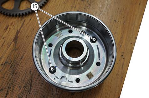
- Start 2 service screws (15) in order to center the six mounting holes
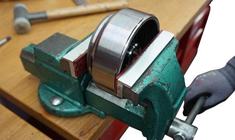
- Fully insert the flange/starter clutch assembly into the new rotor using a vice or hydraulic press
WARNING
During insertion, apply a slight and evenly distributed force on three points, rotating the rotor assembly by 120 degrees, and progressively increasing the vice closing force. This is to prevent the flange from getting stuck on the rotor in an improper position.
- Remove the 2 service screws (15) previously mounted for centering
- Apply Loctite 648 SEALANT to the 6 screws (13) retaining the flange/starter clutch assembly to the rotor

- Start the 6 screws (13) and tighten them to 13 Nm ± 10% respecting the indicated sequence
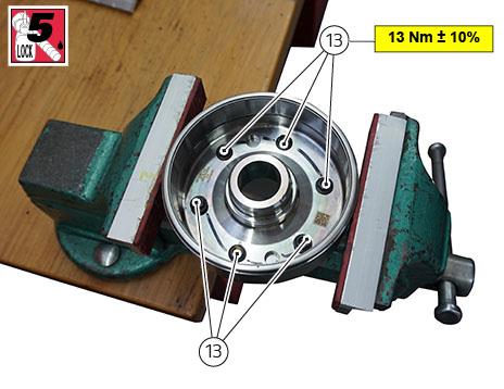
- Use a permanent marker to certify tightening of the 6 screws (13)
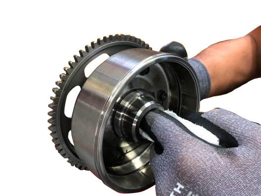
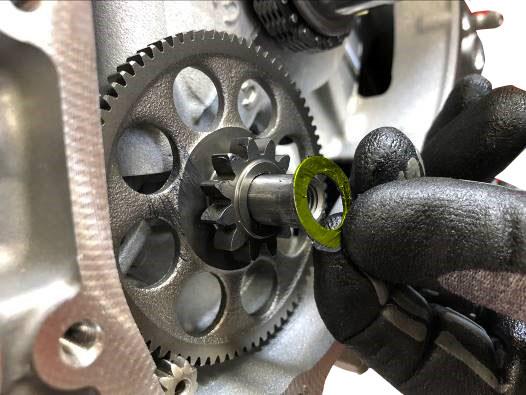
- Remove the starter motor driven gear from the crankshaft and remove the needle roller bearing cage
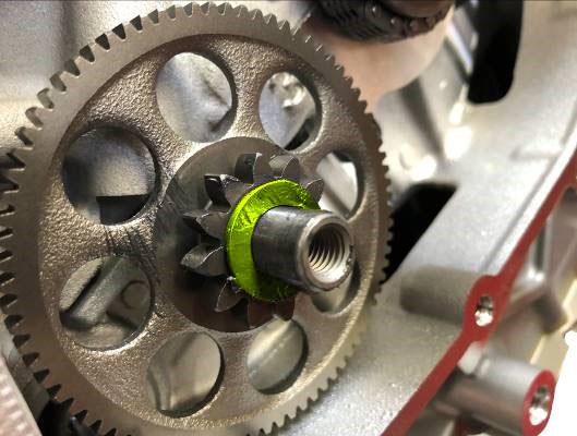
- Thoroughly clean the crankshaft taper coupling on the flywheel side and the inside of the flywheel itself using a commercial degreaser for mechanical parts (contact cleaner or acetone) (see pictures)
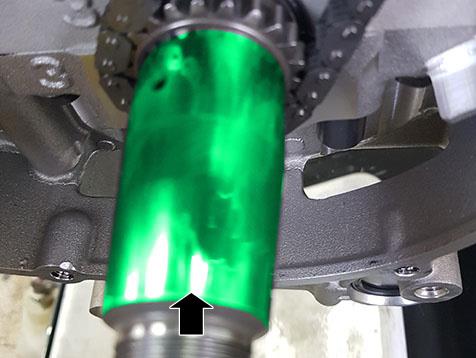
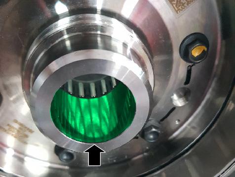
- Check that the stop washer remains on the crankshaft, in the correct assembly direction
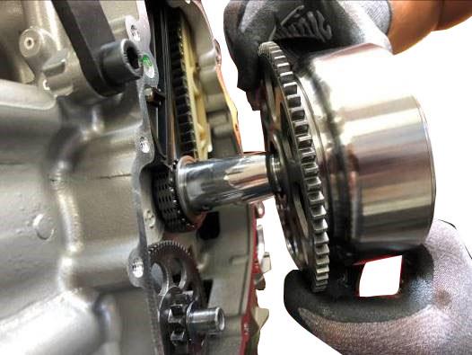
- Fit the starter motor driven gear with the needle roller bearing cage on the rotor assembly (12) by rotating it slightly and applying a moderate force at the same time
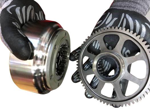
- Check that the washer is on the idle gear
- Install the rotor assembly on the crankshaft, ensuring that the starter motor driven gear engages with the idle gear
- Place tool (B) for flywheel nut removal part no. 88713.8853 and tighten the 5 screws (8)to 10 Nm
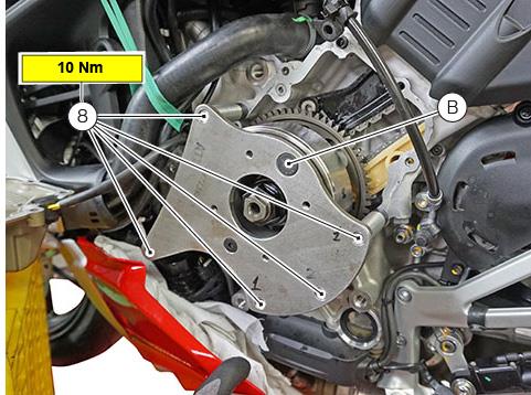
NOTE
Pay attention during alignment of tool (B) in the generator rotor that the two service holes on the generator rotor are not the same, one is bigger than the other. Check the correct insertion.
- Apply Shell Retinax HDX2 grease (or equivalent) on:
- the threading of nut (10) retaining rotor assembly
- in-between nut (10) and washer (11)
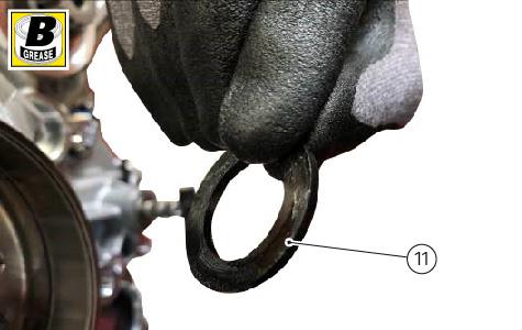
- Start nut (10) with washer (11) in-between
- Tighten nut (10) to 220 Nm ± 5%
- Remove tool (B) for flywheel nut removal part no. 88713.8853
Part 2: Reinstallation of the Generator Cover
- Thoroughly clean the crankcase mating surfaces and generator cover to remove the previous Threebond sealant.
NOTE
A small soft stainless cleaning brush is recommended. DO NOT use sandpaper or other abrasive agents to clean the crankcase and generator cover mating surfaces.
NOTE
Ensure all lubricant residues are cleaned from both mating surfaces prior to applying sealant. Isopropyl alcohol wipes are recommended for surface preparation.
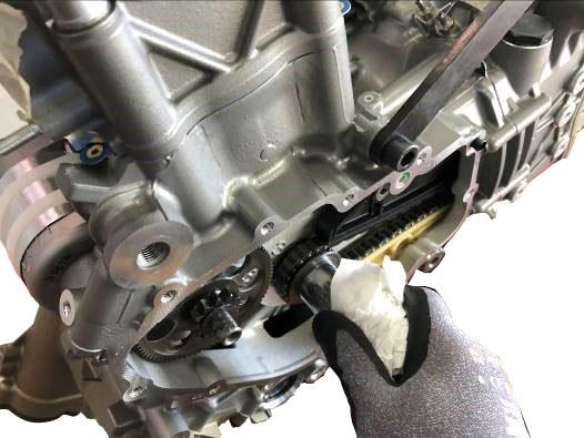
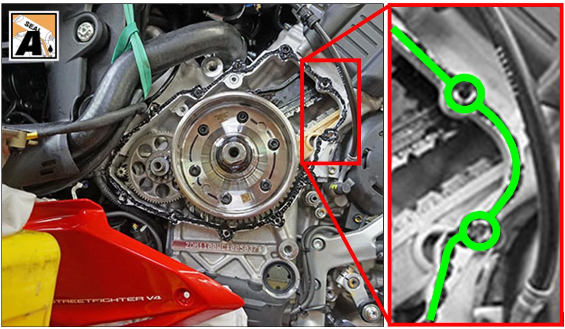
- Apply Threebond 1207B (Fluid Sealant Black, Part no. 942470036) on the crankcase, as shown in the figure.
NOTE
Threebond 1207B (part no. 942470036) has a very short curing time: it is important to close the assembly within 6 minutes after application.
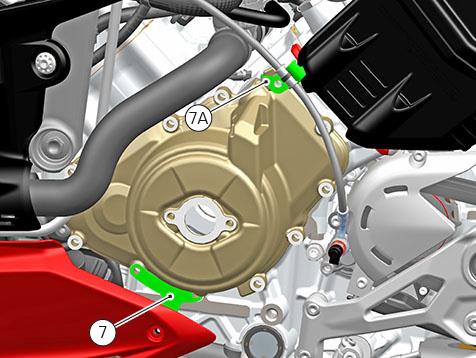
- Position the generator cover on crankcase. Position the bracket (7) retaining the LH lug and the bracket (7A) supporting the clutch hose
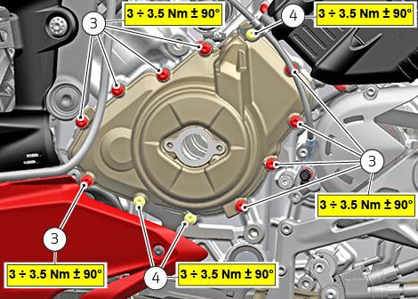
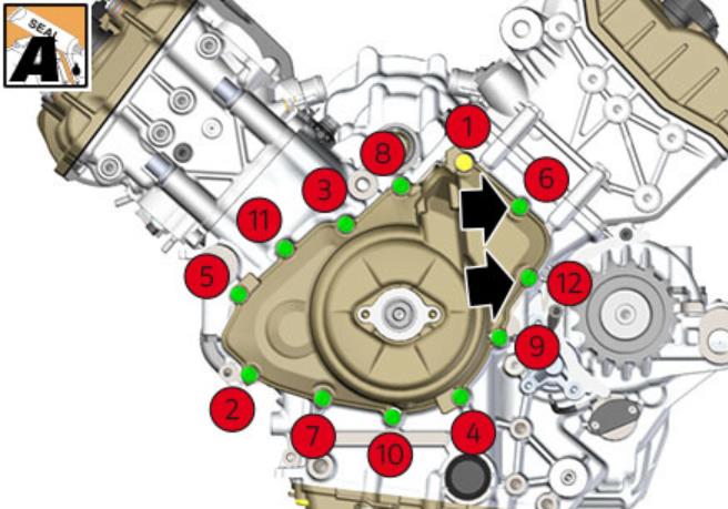
- Start the 9 screws (3) and 3 screws (4) on generator cover and tighten them to 3 ÷ 3.5 Nm
+ 90° angle, following the indicated sequence on the following page
NOTE
Apply the Threebond sealant to the threads to bolts in locations with a clear passthrough hole into the engine timing area (locations 6 and 12 in reference to the diagram on the following page)
NOTE
Due to the recent production of the engines, an exception in this unique circumstance will be allowed to reuse and retighten the aluminum bolts one time. If the generator cover is removed again during the course of the repairs, the aluminum bolts must be replaced
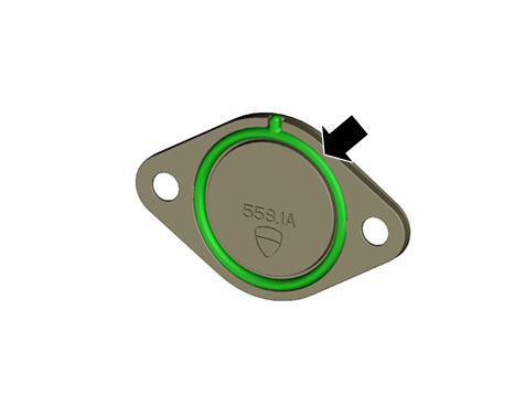
- Check that the gasket is correctly fitted on timing inspection cover, as shown in the figure
- Refit timing inspection cover (2) and tighten the 2 screws (1) to 5 Nm ± 10%.
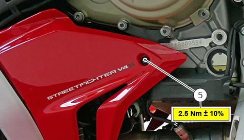
- Fasten LH lug by starting screw (5), with its washer in-between
- Tighten the screw (5) to 2.5 Nm (only for Streetfighter V4)
- Start the engine until the fans switch on, then turn off the engine
- Inspect and ensure there are no oil leaks
- Before delivering the motorcycle to the Customer, check engine oil level in accordance with the waiting period detailed in the repair manual
- Perform a soft cleaning of the bike before delivering it to the Customer
Campaign Authorization
Ducati North America, Inc. will not mail a notification letter as all vehicles in production have not been delivered to the final customer. It is important that you confirm the eligibility for recall status on the DCS before you commence work. Reimbursement requests for duplicate recall campaign repairs will not be accepted.
Dealer Obligation
This program is designed to complete the necessary repairs and to achieve owner satisfaction. Therefore, we ask that you to take prompt and courteous action in accordance with these directives. Please provide a copy of this communication to every person in your dealership who has recall-related responsibilities. Please direct any questions or concerns to your Service Area Manager.
Thank you for your cooperation.
Service Department
Ducati North America, Inc.
For questions on this Safety Recall Campaign, please contact your Service Area Manager.
2 Affected Products
Vehicles
| MAKE | MODEL | YEAR |
| DUCATI | STREETFIGHTER V4 | 2021 |
| DUCATI | STREETFIGHTER V4 S | 2021 |
8 Associated Documents
Recall Quarterly Report #4, 2021-2
RCLQRT-20V460-3718.PDF 211.434KB
 Loading...
Recall Quarterly Report #1, 2020-3
RCLQRT-20V460-0781.PDF 211.143KB
Loading...
Recall Quarterly Report #2, 2020-4
RCLQRT-20V460-7278.PDF 211.244KB
Loading...
Recall Quarterly Report #3, 2021-1
RCLQRT-20V460-3105.PDF 211.327KB
Loading...
Recall Acknowledgement
RCAK-20V460-3674.pdf 244.129KB
Loading...
Defect Notice 573 Report
RCLRPT-20V460-5785.PDF 215.836KB
Loading...
Safety Bulletin
RCSB-20V460-8131.pdf 2153.028KB
Loading...
Recall Quarterly Report #5, 2021-3
RCLQRT-20V460-2311.PDF 211.54KB
Loading...
Latest Recalls Documents
https://www-odi.nhtsa.dot.gov/acms/cs/documentList.xhtml?docId=20V460&docType=RCL

- Formulated with Trizone technology to protect all 3 critical zones: engine, clutch and gearbox
- Race derived technology for maximum engine acceleration
- Extreme high temperature air-cooled performance and water-cooled engine performance
- Excellent shear stability to prevent viscosity breakdown
- Exceeds API SL and JASO MA-2

- 100% Synthetic Ester
- Formulated To Meet The Latest Manufacturers' Specifications
- Improved High Temperature Deposit Protection And Sludge Control
- Ensures Optimum Clutch Performance At Start-Up, Acceleration, And Full Speed
- Standards: Ape Sn, Jasso Ma2

- Optimal lubrication in all operating conditions, ensures low oil consumption
- Very high shear and ageing stability, highest levels of wear protection
- Tested and approved for catalytic converters, optimal engine cleanliness
- Ideally suited for wet clutches
- Specifications and Approvals: API, SM, ACEA A3-04, JASO, MA2
- 100% Synthetic Double Ester
- Designed for highly modified engines
- Electrochemical bonding to metal parts
- Up to 5x higher film strength
- 0% shear loss on Bosch ASTM D6278 test

- Full synthetic 5W-40 diesel engine oil with Triple Protection Plus technology protects against wear, deposits, and oil breakdown
- Improved wear performance with significantly increased level of protection against harmful engine wear (compared to previous generation API CJ-4 engine oils)
- Enhanced fuel economy capability of 1.5% without compromising engine protection or durability (compared to 15W-40 oils)
- Multi-functional dispersant additives provide an enhanced level of protection against the effects of soot, dirt, and other contaminants
- Resists breakdown by heat to provide continuous protection throughout the service interval, and also provides improved low-temperature flow compared to conventional 15W-40 oils

- Race-derived technology for maximum engine acceleration
- Extreme high temperature air-cooled performance and water-cooled engine performance
- Excellent shear stability to prevent viscosity breakdown
- Fit Type: Vehicle Specific


- Optimal lubrication in all operating conditions, ensures low oil consumption
- Very high shear and ageing stability, highest levels of wear protection
- Tested and approved for catalytic converters, optimal engine cleanliness

- Optimal lubrication in all operating conditions, ensures low oil consumption
- Very high shear and ageing stability, highest levels of wearing protection
- Tested and approved for catalytic converters, optimal engine cleanliness
- Ideally suited for wet clutches
- Specifications and Approvals: API, SM, ACEA A3-04, JASO, MA2
- XPS synthetic 4-stroke oil is specifically engineered to meet the particular lubrication requirements of Can-Am, Spyder and Sea-Doo vehicles equipped with Rotax 4-TEC 4-stroke engines.
- Powersport formula with premium anti-wear and anti-corrosion additives
- Designed for high-performance off-road, on-road and PWC 4-stroke engines, including turbo or supercharged Powersports engines
- Provides superior engine and transmission protection against rust and corrosion even in extreme conditions
- Ambient temperature operating range: -31°F / 104°F (-35°C / 40°C)
Last update on 2024-06-10 / Affiliate links / Images from Amazon Product Advertising API
This product presentation was made with AAWP plugin.