
| “This site contains affiliate links for which OEMDTC may be compensated” |
NHTSA ID Number: 10108972
Manufacturer Communication Number: LIT-608-00_4-17
Summary
E/H Brake Actuator Service Manual Update
1 Affected Product
Equipment
| BRAND | PART NO. | PRODUCTION DATES |
| DEXTER | DEXTER | |
OPERATION MAINTENANCE SERVICE MANUAL
ELECTRICALLY CONTROLLED HYDRAULIC
BRAKE ACTUATION DEVICE
E/H 1000 & 1600 BRAKE ACTUATORS
Introduction
This manual has been provided to guide you through the process of installing, operating, and maintaining your Dexter electrically controlled hydraulic brake actuation device (also referred to as E/H brake actuator). This electrically powered unit has been designed and manufactured to give safe, reliable power to your hydraulic trailer brakes.
Before proceeding, make sure that the unit is appropriate for your particular brakes. The E/H 1000 produces 1000 psi, typically used for duo-servo hydraulic drum brakes, while the E/H 1600 produces 1600 psi for most hydraulic disc brakes. Please refer to your brake manufacturer for proper operating pressures.
The Dexter E/H brake actuator is compatible with many electric brake controllers, but the best performance will be achieved using an inertial type controller such as the Dexter Predator DX2®. The electronic timer type of controller is not recommended because these units use a fixed control that does not sense varying brake requirements.
Visit us online at www.dexteraxle.com.
Contents
Actuator Installation Instructions…………………………………………3
Getting Started …………………………………………………………..3
Electrical Installation Requirements ……………………………………6
Wire Colors and Function ……………………………………………6
Test Electrical Operation ……………………………………………………9
Bleeding and Brake Adjustment ……………………………………….10
Testing and Adjustment …………………………………………………..12
Troubleshooting Guide and Replacement Kits ……………………13
Limited Warranty …………………………………………………………….16
| CAUTION |
| This is the safety alert symbol. It is used to alert you to potential injury hazards. Obey all safety messages that follow this symbol to avoid possible injury or death. |
Actuator Installation Instructions
Getting Started
The following materials are required to properly install the Dexter E/H brake actuator. If your trailer is not already equipped with brake lines, you will need enough ³⁄₁₆” diameter automotive brake line to connect the trailer brakes to the unit. Where possible, steel tubing is preferred.
- Four ¹⁄₄” threaded fasteners to mount the unit to the trailer.
- One quart of DOT 3, DOT 4, or DOT 5 brake fluid (from a new sealed container).
- One emergency breakaway kit – must include a 12 volt, 9 amp hour (minimum) battery.
- Wire (see Electrical Installation Requirements for proper wire size).
Location of the Dexter E/H brake actuator is at the discretion of the vehicle owner. When selecting the location, the following items should be considered:
- The shorter the wiring between the unit and the electrical power source, the smaller the voltage drop.
- The unit should be located so that the electrical wiring and brake lines can be neatly routed directly to the towing vehicle and trailer brakes. Special care should be taken to minimize the number of bends and fittings in the brake line circuits.
- An emergency breakaway kit must be located on the trailer so that the trailer breakaway cable can be easily attached to the towing vehicle.
- The Dexter E/H brake actuator is powered from the electrical system on the tow vehicle. In order for the unit to function properly, it must have adequate electrical power (see Electrical Installation Requirements).
- The Dexter E/H brake actuator should not be placed in an area where it is susceptible to damage from trailer loads, road debris, or from being stepped on. Failure to protect the actuator from damage can cause the unit to malfunction and void the Dexter Axle warranty.
Mounting consideration should be given to the following:
- The unit must be level, with the filler neck up.
- It is the responsibility of the customer to provide necessary fasteners for attachment of the actuator to the trailer.
- Mount unit where it will not be submerged in water.
- Mounting near the hitch is preferred. Do not mount near the trailer axles or rear of the trailer.
| CAUTION |
| The Dexter E/H brake actuator contains sensitive electronics that must be protected. Drilling additional holes in the housing, electrostatically painting, or welding anywhere on the unit will damage the unit making it inoperable and will void the manufacturer’s warranty. Always remove the unit from the trailer before doing any welding repair or modifications to the trailer structure. |
Connect the trailer brake lines to the actuator as follows:
- Remove the rubber or plastic plug from the ³⁄₁₆” inverted flare brake port.
- Brake line must be compatible with DOT 3, DOT 4, or DOT 5 brake fluid.
- Flush existing brake system and lines until thy are free of any contaminants using DOT 3, DOT 4, or DOT 5 brake fluid prior to connecting to the Dexter E/H brake actuator.
- Connect the brake line from the trailer brakes to the ³⁄₁₆” inverted flare fitting on the actuator. Do not tighten the ³⁄₁₆“ brake line adapter more than the 22 Ft. Lbs. used at factory installation.
Fill the unit with DOT 3, DOT 4, or DOT 5 brake fluid to the bottom of the reservoir filler neck. When putting the filler cap back on it should be turned clockwise until snug.
| CAUTION |
| Always use new DOT 3, DOT 4, or DOT 5 brake fluid from a sealed container. Never attempt to reuse old or dirty fluid. Do not overfill the unit. Take care to protect painted surfaces from contact with the brake fluid.
Wash off any spilled brake fluid. |
Mount the emergency breakaway switch and emergency breakaway battery on the trailer, as detailed in the instruction sheets provided with the emergency breakaway kit.
Bolt Mounting Pattern
Electrical Installation Requirements
| CAUTION |
| Undersized wire will increase electrical resistance and will prevent proper operation of this unit. |
Wire Colors and Function
BLACK – 30 amp 12 volt supply from tow vehicle*
BLUE – Output from electronic brake controller in tow vehicle
WHITE – Trailer and tow vehicle ground
YELLOW – Cold side of breakaway switch
Electrical Schematic
It is important that wire lengths for the BLACK power lead and WHITE ground lead be no longer than 25 feet from the E/H brake actuator to the supply power (i.e. on board trailer battery or the tow vehicle battery). The E/H brake actuator needs to be located as close as possible to the battery near the front of the trailer. DO NOT mount the E/H brake actuator near the trailer axles or rear of the trailer. Having the wire length longer than 25 feet may cause issues with performance and the normal operation of the unit.
It is critical that the BLACK power lead and WHITE ground lead from the tow vehicle to the input of the actuator are sized and properly terminated (i.e. dedicated 30-40* amp circuit on the tow vehicle – 12 gauge wire minimum). 10-gauge wire is recommended to optimize performance. Consult the SAE wiring guidelines for proper trailer electrical harness design.
* Low temperature applications below 0°F require a 40-amp circuit.
The blue wire from the electric brake controller is connected through the trailer plug to the blue wire on the actuator. The yellow wire from the E/H brake actuator is connected to the cold side of the trailer emergency breakaway switch. Under no circumstances should the actuator blue wire and the E/H brake actuator yellow wire be connected together, nor should the blue wire ever be grounded.
The white wire is connected to the trailer ground and also connected to the tow vehicle ground through the trailer plug. The black wire is connected to the +12V power line from the tow vehicle. The black wire can also be connected to large on-board coach batteries. The black wire is connected to the small breakaway battery only through the black wire on the charger of the breakaway battery.
Requires an Electric Brake Controller – The Dexter E/H brake actuator is intended to be used with an electric brake controller in the tow vehicle. The unit will operate with a wide variety of controllers but provides optimum performance when used with a Dexter electric brake controller . The electric brake controller must have an output capacity of at least 5 amps for proper operation of the Dexter E/H brake actuator. Although compatible, time base brake controllers are not recommended.
| CAUTION |
| It is the responsibility of the end user to ensure that their electric brake controller is compatible with the Dexter E/H brake actuator. Dexter Axle attempts to provide compatibility with most controllers available, but is unable to anticipate design changes that might be introduced by the various controller manufacturers. |
Electrical Connections – Make sure all electrical connections are clean, dry, weather tight, and secure to prevent damage to the wiring from dragging or becoming entangled with foreign objects. A dedicated ground connection between the tow vehicle and trailer is also required.
Breakaway Battery Requirement – To comply with federal requirements, the trailer must be equipped with a breakaway switch and battery. The breakaway battery needs to have a minimum capacity of 9 amp hours and needs to be maintained in a fully charged condition at all times. The breakaway battery should be checked for proper charge level before every use.
Charging the Breakaway Battery – The breakaway battery must be kept fully charged at all times in order to function properly. Use only those breakaway battery kits that include a charging device. Do not attempt to charge the breakaway battery directly from the tow vehicle without the appropriate charging device.
Test Electrical Operation
- Attach the trailer to the towing vehicle. Do not connect trailer plug to tow vehicle until step #2 is completed.
- Pull the breakaway switch. The Dexter E/H brake actuator should run. If the unit does not run, check breakaway battery condition and system wiring. Reset the breakaway switch, which will turn the unit off.
Note: When the unit is running, the motor will generate a “hum” that changes pitch as the unit builds pressure. This is normal.
- Connect trailer plug to tow vehicle.
- Turn the ignition switch on and turn the electric brake controller on. Whenever the brake pedal is depressed, the Dexter E/H brake actuator should run with time based controllers. Inertia type controllers will often require the vehicle to be moving in order for the Dexter E/H brake actuator to come on by means of the brake pedal. If the unit does not run, check system wiring.
- Apply the controller manual slide. The Dexter E/H brake actuator should run and brake lights come on.
| CAUTION |
| Testing the Dexter E/H brake actuator confirms that it is operating. It DOES NOT confirm that the brakes are operating properly. Regular inspection, adjustment, and maintenance of the brakes, lines, hoses, drums, discs, fluid, and other associated components is necessary to ensure proper brake operation. |
- Some brake controllers will not produce a high enough signal voltage to actuate the trailer brakes when the vehicle is at a standstill. Minimal trailer brake force is produced when the controller voltage output to the E/H brake actuator is at least 3 VDC. Maximum trailer brake force is achieved at 12 VDC on the actuator blue wire.
- When the tow vehicle brakes are released, the unit may continue to run for a few seconds.
Bleeding and Brake Adjustment
- It typically is much easier to bleed the brakes with two people working together.
- Special care must be taken to insure that the Dexter E/H brake actuator does not run out of brake fluid. Check the fluid level frequently during the bleeding process.
- Block the wheels on the trailer and towing vehicle.
- If the trailer is equipped with drum brakes, check that the brake running clearances are properly adjusted consistent with the trailer manufacturer’s recommendations.
| CAUTION |
| Failure to properly adjust the brakes on trailers equipped with drum brakes can result in slower response time of the Dexter E/H brake actuator. |
- Install plastic tubing onto the bleeder screw of the wheel cylinder/caliper farthest from the Dexter E/H brake actuator. If towed vehicle has multiple axles, always start with the rear axle first.
- Immerse the free end of the plastic tube in a clean clear container partially filled with brake fluid.
- Open the bleeder screw one half turn on the wheel cylinder/ caliper.
- To activate the Dexter E/H brake actuator, turn the ignition switch on and use manual slide on the brake controller.
- Watch the free end of the bleeder hose for air bubbles escaping into the clear container. Continue to bleed the wheel cylinder/caliper until the fluid becomes clear and free of bubbles.
| CAUTION |
| Do not run the Dexter E/H brake actuator without adequate brake fluid in the reservoir as it may damage the unit and void the warranty. Check all bleeder screws to ensure that they are securely closed and do not leak. |
- Tighten the bleeder screw, turn off the Dexter E/H brake actuator, and remove plastic tubing from the bleeder screw. Bleeding of the wheel cylinder/caliper is now complete.
- Refill the Dexter E/H brake actuator with brake fluid.
- Continue the above process (steps 5 through 11) on the next farthest brake away from the actuator.
- Repeat these steps until all the brakes have been bled.
- New trailers with disc brakes should be bled at least twice. Any air in the brake system will cause brake delay with an E/H brake actuation system.
Testing and Adjustment of Electronic Controller Unit
- Adjust the gain setting on the electric brake controller to a mid range setting.
- Drive vehicle at 10 to 15 m.p.h.
- Apply the brakes. If braking is too severe, adjust the gain setting down to decrease pressure and retest. If braking is inadequate, increase the gain setting on the electric brake controller and retest.
- Repeat this process until the brakes respond appropriately.
| CAUTION |
| The appropriate pressure setting will vary depending on the weight of the load being transported on the trailer, weather conditions and road conditions. The “Testing and Adjustment of Electronic Controller Unit” procedure should be repeated each time the trailer is used. Failure to properly adjust the Dexter E/H brake actuator may result in poor brake performance and could result in serious or fatal injuries and/or property damage. |
Troubleshooting Guide
Unit will not run or brakes are slow to respond. To determine if the unit is functioning properly, perform the checks outlined below
- Verify that the trailer and tow vehicle are wired according to the electrical schematic shown in “Electrical Requirements”.
- Re-bleed the trailer brakes. Any air in the trailer brake system causes brake delay.
- If the trailer is equipped with drum brakes, re-adjust the drum brakes to the trailer manufacturer’s recommended running clearance.
- Trailer wiring that is too small can cause slow response (see section on Electrical Installation Requirements).
- Slow response can be caused by brake line restrictions. The trailer brake lines must be at least ³⁄₁₆” in diameter. Steel tubing must be used as much as possible. Using too much flexible hose may cause slow brake response.
- Check to see if the white ground wire runs directly to the tow vehicle ground. IT MUST NOT BE GROUNDED TO THE
TRAILER ONLY. IT IS IMPORTANT THAT THIS GROUND WIRE RUNS DIRECTLY TO THE TOW VEHICLE’S BATTERY GROUND. NO EXCEPTIONS.
- Detach all wires from the Dexter Axle E/H brake actuator leaving the blue, black, white, and yellow wires loose. It is important that the unit is disconnected from any other wires going to the towing vehicle or breakaway switch and breakaway battery. Failure to do so may result in a faulty test.
- Using a 12 volt battery, connect the white wire to the negative (-) terminal of the battery.
- Connect the black wire to the positive (+) terminal of the battery and the E/H brake actuator will click once. The motor should not run. If the motor runs, the E/H brake actuator may be defective.
- Leave the white wire connected to the negative (-) terminal of the battery.
- Connect the blue and black wires together to the positive (+) terminal of the battery.
- The motor should run and the unit should pressurize.
- If this does not occur, the unit may be defective.
- Leave the white wire connected to the negative (-) terminal of the battery.
- Connect only the yellow wire to the positive (+) terminal of the battery.
- The motor should run and the unit should pressurize.
- If this does not occur, the unit may be defective.
- If the unit checks OK, reconnect the wires leading to the trailer plug and repeat steps 8 through 14 at the trailer plug. If you do not get the same results as before, the problem is in the trailer wiring or the electronic brake controller. Using the breakaway system to troubleshoot a unit that is not operating correctly
- With a fully charged breakaway battery and trailer plug disconnected, pull the breakaway switch on the trailer. a. If the unit runs and builds pressure, the breakaway system is functioning properly.
- If the unit runs and builds pressure when the breakaway switch is pulled but will not function under normal operating conditions, the problem most likely is a defective electric brake controller or defective wiring between the tow vehicle and Dexter E/H brake actuator.
- If the unit runs but will not build pressure when the breakaway switch is pulled, the Dexter E/H brake actuator may be malfunctioning.
- If the unit does not run, measure the DC voltage between the white wire and the yellow wire. If the voltage is less than 12 volts, either the breakaway switch or the breakaway wiring is defective.
- After completing the above steps, reset the breakaway switch and reconnect the trailer plug.
Trailer brakes too aggressive
- Reduce the gain setting on the electric brake controller.
- Check brake adjustment.
Trailer brakes not aggressive enough
- Increase the gain setting on the electric brake controller.
- Check brake adjustment.
Replacement Kits
| Description | Kit Number |
| E/H Brake Actuator Fill Cap & Gasket | K71-685-00 |
| E/H Brake Actuator Gaskets | K71-688-00 |
SEOCONTENT-START
Dexter Axle Limited Warranty
What Products Are Covered
All Dexter Axle Company (“Dexter”) trailer axles, suspensions,
and brake control systems manufactured on or after September 1,
2016, excluding Dexter 6000 series Manufactured Housing Axles.
Additional exclusions include the following brands: UFP by Dexter,
AL-KO (IAC), Titan Brakes and Actuators by Dexter, and BrakeRite
by Dexter products, which are covered under separate warranties.
Limited 1 Year Warranty
As specified in Dexter’s current publication “Operation
Maintenance Service Manual”, grease and oil seals FOR ALL
PRODUCTS have a one (1) year limited warranty to the original
purchaser from the date of first sale of the trailer incorporating
such components. Except as to grease and oil seals, the
following four other warranties are available.
Limited 2 Year Warranty
Dexter warrants to the original purchaser that its electric/hydraulic
brake actuators shall be free from defects in material and
workmanship for a period of two (2) years from the date of first
sale of the trailer incorporating such components.
Limited 5 Year Warranty
Dexter warrants to the original purchaser that its axles,
suspension systems and Genuine Replacement Parts shall be
free from defects in material and workmanship for a period of five
(5) years. The warranty period shall begin from the date of the
original purchase of the trailer and/or Genuine Replacement Parts.
Limited 7 Year Warranty
Dexter warrants to the original purchaser that its Predator Series®
electric brake controllers shall be free from defects in material
and workmanship for a period of seven (7) years from the date of
purchase.
Limited 10 Year Warranty
Dexter warrants to the original purchaser that the suspension
components of its Torflex® axles shall be free from defects in
material and workmanship for a period of ten (10) years from
the date of first sale of the trailer incorporating such suspension
components.
Exclusive Remedy
Dexter will, at its option, repair or replace the affected components
of any defective axle, repair or replace the entire defective
Limited Warranty
-17-
axle, or refund the lesser of the original purchase price and the
then-current list price of the axle or components. In all cases, a
reasonable time period must be allowed for warranty repairs to
be completed. Allowance will only be made for installation costs
specifically approved by Dexter.
What You Must Do
In order to make a claim under these warranties:
1. You must be the original purchaser of the trailer in which the
sprung suspension axles or Torflex® axles or components were
originally installed.
2. You must promptly notify Dexter after detection of any defect,
but in any case within the applicable warranty period of such
defect, and provide us with the axle or applicable component
serial number and any substantiation of such defect which may
include, but is not limited to, the return of part(s) that we may
reasonable request.
The axles, suspensions and components must have been installed
and maintained in accordance with good industry practice and
any specific Dexter recommendations, including those specified
in Dexter’s current publication “Operation Maintenance Service
Manual”.
Exclusions
These warranties do not extend to and do not cover defects
caused by:
1. The connecting of brake wiring to the trailer wiring or trailer
wiring to the towing vehicle wiring.
2. The attachment of the running gear to the frame.
3. Parts not supplied by Dexter.
4. Any damage whatsoever caused by or related to any alteration
of the axle including welding supplemental brackets to the axle.
5. Use of an axle on a unit other than the unit to which it was
originally mounted.
6. Normal wear and tear.
7. Improper alignment.
8. Improper installation.
9. Unreasonable use (including failure to provide reasonable
and necessary maintenance as specified in Dexter’s current
publication “Operation Maintenance Service Manual including
required maintenance after “Prolonged Storage”).
Limited Warranty
-18-
10. Improper torque values and torqueing of wheel nuts. (The
proper torqueing procedure and torque values are contained
in Dexter’s current publication “Operation Maintenance Service
Manual”).
11. Cosmetic finish or corrosion.
Limitations
1. In all cases, Dexter reserves the right to fully satisfy its
obligations under the Limited Warranties by refunding
the lesser of the original purchase price and the thencurrent
list price of the defective axle (or, if the axle has
been discontinued, of the most nearly comparable current
product).
2. Dexter reserves the right to furnish a substitute of replacement
component or product in the event an axle or any component
of the axle is discontinued or is otherwise unavailable.
3. These warranties are nontransferable.
General
THE FOREGOING WARRANTIES ARE EXCLUSIVE AND IN
LIEU OF ALL OTHER WARRANTIES EXCEPT THAT OF TITLE,
WHETHER WRITTEN, ORAL OR IMPLIED, IN FACT OR IN LAW
(INCLUDING ANY WARRANTY AGAINST INFRINGEMENT OR
OF MERCHANTABILITY OR FITNESS FOR A PARTICULAR
PURPOSE).
These warranties give you specific legal rights, and you may also
have other rights which vary from state to state.
DEXTER HEREBY EXCLUDES INCIDENTAL AND
CONSEQUENTIAL DAMAGES, INCLUDING LOSS OF TIME,
INCONVENIENCE, LOSS OF USE, TOWING FEES, TELEPHONE
CALLS, COST OF MEALS OR LODGING, FOR ANY BREACH
OF ANY EXPRESS OR IMPLIED WARRANTY.
Some states do not allow limitations on how long an implied
warranty lasts, or the exclusion or limitation if incidental or
consequential damages, so the above exclusion or limitation may
not apply to you.
Inquiries regarding these warranties should be sent to:
Dexter Axle Company
P.O. Box 250
Elkhart, IN 46515
Note: Current publication “Operation Maintenance Service Manual”
can be found at www.dexteraxle.com.
Limited Warranty
-19-
Dexter video Gallery
Dexter Video Gallery
In keeping with our continual commitment to industry safety and
the development of innovative products, please feel free to view
our ongoing video gallery at www.dexteraxle.com/resources/
videos or scan the following QR codes. We are confident these
videos will help educate and promote the Dexter product line that
you, as our customer, are investing in.
Bearing
Maintenance
E/H Actuator
Installation
Electric Brakes
E-Z Flex®
Suspension
E-Z Lube®
System
Genuine Brakes
Genuine
Replacement Parts
Leaf Spring
Axles
Manual Bleed
Hydraulic Disc
Medium Duty
Axles
Nev-R-Adjust®
Brakes
Power Bleed
Hydraulic Disc
Removable
Spindle
Sway Control Torflex®
Suspension Axles
-20-
Dexter Online Parts Store
From magnets and seals to complete brake and hub kits, Dexter offers a
complete line of genuine replacement parts for your trailer. Most products
are available in-stock and ready to ship within 24 hours direct to you from
the factory. With dedicated customer support and quick turnaround, the
Dexter Online Parts Store helps keep your trailer going.
• Hub Components
• Brake Components
• Suspension Components
• Complete Hub Kits
• Brake Assemblies & Kits
• Brake Controllers & Actuators
Ready for Immediate Shipment
Direct to Your Door
Visit us online at www.dexteraxle.com
-21-
Notes
-22-
Notes
-23-
Notes
Genuine Dexter axles and components are available
nationwide from our plant locations listed below or
through our network of distributors. Check our web site
for the distributor nearest you.
NO PART OF THIS CATALOG MAY BE REPRODUCED WITHOUT DEXTER’S PERMISSION.
ALL PART NUMBERS, DIMENSIONS AND SPECIFICATIONS IN THIS CATALOG ARE SUBJECT
TO CHANGE WITHOUT NOTICE.
Dexter – Headquarters
2900 Industrial Parkway East Elkhart, Indiana 46516
Phone: 574-295-7888 Fax: 574-295-8666
www.dexteraxle.com
Dexter – Plt 12
301 West Pearl Street
Fremont, Indiana 46737
Phone: 260-495-5100
Fax: 260-495-1701
Dexter – Plt 13
500 South 7th Street
Albion, Indiana 46701
Phone: 260-636-2195
Fax: 260-636-3030
Dexter – Plt 15
500 Southeast 27th Street
El Reno, Oklahoma 73036
Phone: 405-262-6700
Fax: 405-262-9089
Dexter – Plt 21
199 Perimeter Road
Monticello, Georgia 31064
Phone: 706-468-6495
Fax: 706-468-2966
Ventline – Plt 39
902 South Division Street
Bristol, Indiana 46507
Phone: 574-848-4491
Fax: 574-848-4825
www.ventline.com
Dexter Door – Plt 39
902 South Division Street
Bristol, Indiana 46507
Phone: 574-848-4491
Fax: 574-848-4825
www.dexterdoor.com
Dexter – Plt 61
21611 Protecta Drive
Elkhart, Indiana 46516
Phone: 574-294-6651
Fax: 574-295-6626
Dexter – Plt 62
301 North Kennedy Street
Shawnee, Oklahoma 74801
Phone: 405-273-9315
Fax: 405-273-1054
UFP – Plt 24
135 Sunshine Lane
San Marcos, California 92069
Phone: 760-744-1610
Fax: 760-744-1616
UFP – Plt 25
1041 Baxter Lane
Winchester, Tennessee 37398
Phone: 931-967-5101
Fax: 931-967-1828
UFP
Plant 24
UFP
Plant 25
Dexter Headquarters
Plants 12, 13, 39, 61
Plant 21
Plants 15, 62
www.dexteraxle.com
2900 Industrial Parkway East n Elkhart, IN 46516
Phone: 574-295-7888 n Fax: 574-295-8666
ISO 9001 Certified
GEARED FOR INNOVATION SINCE 1960
4/17 © 2005-2017 Dexter Axle Company. LIT-608-OO
LIT-608-00_4-17
https://www.nhtsa.gov/recalls?nhtsaId=10108972
https://static.nhtsa.gov/odi/tsbs/2017/MC-10108972-9999.pdf
 Loading...


- Self-Adjusting Electric Brake: Say goodbye to manual adjustments! Dive into the world of 12" x 2" electric trailer brake assemblies that self-adjust. It's not just smart; it's efficient and gives your trailer that smooth braking touch.
- Hassle-Free Installation: DIY's best friend! Our electric trailer brake is straightforward and a breeze to install. It's ready to install right out of the box and boasts high compatibility. Wherever you are, installation is just a few steps away.
- Built for the Long Haul: Keep on rolling! With a lifespan of up to 30,000 kilometers, these trailer brakes are in it for the long haul, designed for your trailer's daily adventures. Constructed from premium materials, our brakes promise robust durability and resistance to wear and tear.
- Versatility at Its Best: The trailer brake kit has a broad range of applications, including towing trailers, transporting goods, camping trips, and more. It's compatible with Dexter, AL-KO (a brand under the former), and other trailer axles.
- Top-Notch Packaging: When it comes to packaging, we don't just box; we care. Our trailer electric brake kit is packaged above industry standards. Every brake is meticulously checked and wrapped to ensure what you get is nothing short of perfect.
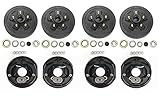
- 4 x trailer 5 on 4.5" hub drum kits + 4 x 10"x2-1/4" electric brakes for Dexter and other brands 3,500 lbs trailer axle
- Drum Bolt pattern: 5 on 4.5", bearing races and 1/2"-20 studs installed, Ref part #. 008-247-05, 84546
- Kits also includ: 4x L68149 inner cone bearings and 4x L44649 outer cone bearings, 4x Grease seals 1.719" x 2.565", 4x E Z lube grease caps with rubber plug; 20 cone wheel nuts 1/2"-20 thread
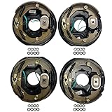
- Also include: 2 left + 2 right 10"x2-1/4" electric brakes with 3" center bore and 4" mounting bolts circle diamter

- Compatible with: Fit For Alko/ for Dexter/ for Quality, and other brands 3,500lbs trailer axle
- Kit Includes: 2x 10" x 2-1/4" left electric brake assemblies, 2x 10" x 2-1/4" right electric brake assemblies, 16x spring pad, 16x nut
- Production and Installation: Strictly follow automotive standards and comply with the G3000 standard in the US; Easy to install
- Product Introduction: The AEagle electronic brake features non-asbestos brake linings for superior friction performance, ensuring longevity and enhanced braking capabilities.
- Quality Assurance: 12-month warranty! Tested before shipping.

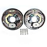
- Compatible with : For Alko/ for Dexter/ for Quality, and other brands 5,200 lbs 6,000 lbs, and 7,000lbs trailer axle
- Kit Includes: 1x 12" x 2" left electric brake, 1x 12" x 2" right electric brake, 10x bolt, 10x spring pad, 10x nut
- Production and Installation: Strictly follow automotive standards and comply with the G3000 standard in the US; Easy to install
- Product Introduction: The AEagle electronic brake features non-asbestos brake linings for superior friction performance, ensuring longevity and enhanced braking capabilities.
- Quality Assurance: 12-month warranty! Tested before shipping.

- 10" x 2.25"electric trailer brake assembly (left & right side), fit most 3500lbs - 4000lbs trailer axle; 4-hole mount w/mounting bolt
- Fits the wheel bolt pattern 4 lug,fits spline size #84 steel drum; center hole diameter: 3" ; bolt circle diameter: 4"
- Replace 023-026-00 and 023-027-00;77-10-2;23-105, 23-106,296649;replace Dexter Lippert Al-Ko,etc brake assemblies
- The electric brakes are NOT self adjusting, unlike most drum brakes on cars and trucks,need to be done when installed and periodically thereafter.If you cannot adjust yourself, please find a professional adjustment
- JADODE electric and hydraulic trailer brake parts Making it an Ideal Choice for Travelers Seeking a Hassle-Free Power Solution

- Premium LIBRA OE 12" x 2" self adjusting electric trailer brake assemblies (2 left + 2 right) for two axle
- works with most 5,200 - 7,000 lbs trailer axles in the market
- Center Hole Diameter: 3-1/4", 5 holes mounting,
- Exchange with Dexter brake # 023-180-00/023-181-00
- Self adjusting, no more manual adjusting

- 2-Pack of TruRyde 12" x 2" self-adjusting electric brake assemblies. Contains 2 left and 2 right brake assembly.
- 5 Hole mounting for 5,200 lbs., 6,000 lbs., and 7,000 lbs. trailer axles.
- Comes with mounting bolts, nuts, and lock washers
- Works with Al-Ko, Dexter, Lippert,and Quality Trailer Axles
- Geniune TruRyde Brakes. TruRyde parts are manufactured to automotive standard in ISO/TS-16949 registered factory.
- Pair of 10" x 2.25" TruRdye electric trailer brake assemblies with parts.
- 4 Hole mounting, comes with mounting bolts, nuts, and lock washers
- For Alko, Dexter, Quality, or other popular trailer axle manufacturers.
- TruRyde Brakes
- TruRyde parts are manufactured to automotive standard in ISO/TS-16949 registered factory.
Last update on 2024-06-11 / Affiliate links / Images from Amazon Product Advertising API
This product presentation was made with AAWP plugin.