| “This site contains affiliate links for which OEMDTC may be compensated” |
October 3, 2019 NHTSA CAMPAIGN NUMBER: 19V702000
If the suspension fails, a sudden loss of vehicle control can result, increasing the risk of a crash.
NHTSA Campaign Number: 19V702
Manufacturer Jayco, Inc.
Components SUSPENSION
Potential Number of Units Affected 908
Summary
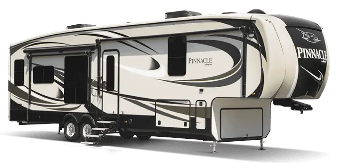
Jayco, Inc. (Jayco) is recalling certain 2017 Pinnacle Fifth Wheel trailers. The suspension system may fail.
Remedy
Jayco will notify owners, and dealers will inspect the condition of the leaf spring, rubber equalizer and bump stop clearance, and provide replacement of the leave spring or rubber equalizer if necessary. This repair will be done free of charge. Interim notices notifying owners of safety risk were mailed December 2, 2019. The recall began December 20, 2019. Owners may contact Jayco customer service at 1-800-517-9137. Jayco’s number for this recall is 9901443.
Notes
Owners may also contact the National Highway Traffic Safety Administration Vehicle Safety Hotline at 1-888-327-4236 (TTY 1-800-424-9153), or go to www.safercar.gov.
NHTSA is missing critical, required information for this safety recall. This information must be supplied through the NHTSA Recalls Portal within 5 working days of confirming its accuracy:
– A description of the defect or noncompliance, including both a brief summary and a detailed description, with graphic aids as necessary, of the nature and physical location (if applicable) of the defect or noncompliance (49 CFR 573.6 (c)(5)).
– An identification and description of the risk to motor vehicle safety reasonably related to the defect or noncompliance (49 CFR 573.6 (c)(5)).
– A statement that the defect or noncompliance can cause a vehicle crash without prior warning; or a description of whatever prior warning may occur, and a statement that if this warning is not heeded, a vehicle crash can occur (49 CFR 577.5 (f)(1)).
– In the case of a defect, a chronology of all principal events that were the basis for the determination that the defect related to motor vehicle safety, including a summary of all warranty claims, field or service reports, and other information (such as numbers of deaths and/or injuries), with their dates of receipt (49 CFR 573.6 (c)(6)).
Pinnacle Suspension Inspection & Bump Stop Installation
| Bulletin #: | 19V-702 US
2019-551 Canadian |
Make: | Jayco |
| Job Code: | 9901443 | Model: | Pinnacle FW |
| Flat Rate(s): | RC024 Inspect Vertical Axle Clearance .2 Hour
RC025 Inspect all 4 leaf springs .5 Hour RC026 Replace 4 leaf springs 2.5 Hour RC027 Replace 2 Rubber Shear Springs 1.7 Hour RC028 Install 4 bump stops .7 Hour |
Model Year(s): | 2017 |
| Incident: | Inspect Pinnacle Suspension System components for proper load dimensions. If dimensions are out of specification, the leaf springs and/or rubber shear springs may require replacement.
Note: ALL units WILL require installation of four (4) rubber bump stops. |
| Affected Units: | ALL 2017 Model Year Pinnacle Fifth Wheels |
| Parts Kits:
19V-702A Bump Stop 19V-702B Steel Leaf Spring 19V-702C Rubber Shear Spring |
19V-702A Bump Stop Kit–4 per Unit (Quantities shown below are per unit)
4-Bump Stop Assembly Jayco #2000322 8-Hex Bolts 5/16-18 x 5” GR5, Jayco #2000323 8-Washer Flat 5/16, Jayco #0011766 8-Washer Lock Split 5/16, Jayco #0011773 8-Nut Hex 5/16-18 GR5 Jayco #0011665 1-Gauge Block Wood 2 ¾” x 2 ¾” x ½” Jayco #2000321
19V-702B Leaf Spring Kit–4 per Unit (Quantities shown below are per unit) 4-Double eye- 7-leaf spring stacks w bronze bushings, Jayco # 2000292 8-U bolts .56-18 x 7.25” Zinc, Jayco #0309179 16-Nut Hex .56-18 GR8 Zinc, Jayco #0309194 (u bolt) 16-Washers, Flat Hardened 9/16, Jayco #0088280 (u bolt) 8-Bolt Shackle (Wet) Shoulder .56 x 3.24”, Jayco #0315400 (leaf spring) 8-Nut .44-20 Prevision TQ Zinc, Jayco #0297635 (leaf spring) NOT IN PARTS KIT 4-Leaf Spring tie plates, use component on repair unit
19V-702C Rubber Shear Spring Kit–2 per Unit (Quantities shown below are per unit) 2-LRE4000-24 Rubber Shear Spring, Jayco #0276717 1-LRE4000-24 Hardware Installation Kit, Jayco #0276718 |
| Misc. Tools & Supplies: | Screw gun
1/2” wrench Tape Measure & 28” long steel straight edge Torque Wrench Adjustable (0-50 Ft/lbs.) |
Section I: TRAILER SUSPENSION COMPONENT INSPECTION
These instructions detail the inspection and service work required on the 2017 Pinnacle fifth wheel as follows:
Section I: Provides steps required to inspect the suspension components and installation of a rubber bump stop above each axle in four locations.
Section II: Provide the detailed instruction for removing and replacing Steel Leaf Springs
Section III: Provide the detailed instructions for removing and replacing the rubber shear spring
Section I – Step 1: INITIAL SETUP OF THE TRAILER
STEP 1:
- Position the unit on a flat level surface.
- Support the unit on the pin box using a suitable stand or a forklift (Fig 1).
- The unit must be in a level condition.
- Retract ALL stabilizer jacks.
- The unit can be in an “as loaded” state, however not to exceed 3500 pounds for any one tire.
- Record tire weights on inspection sheet in the space provided (page 3 of this document)
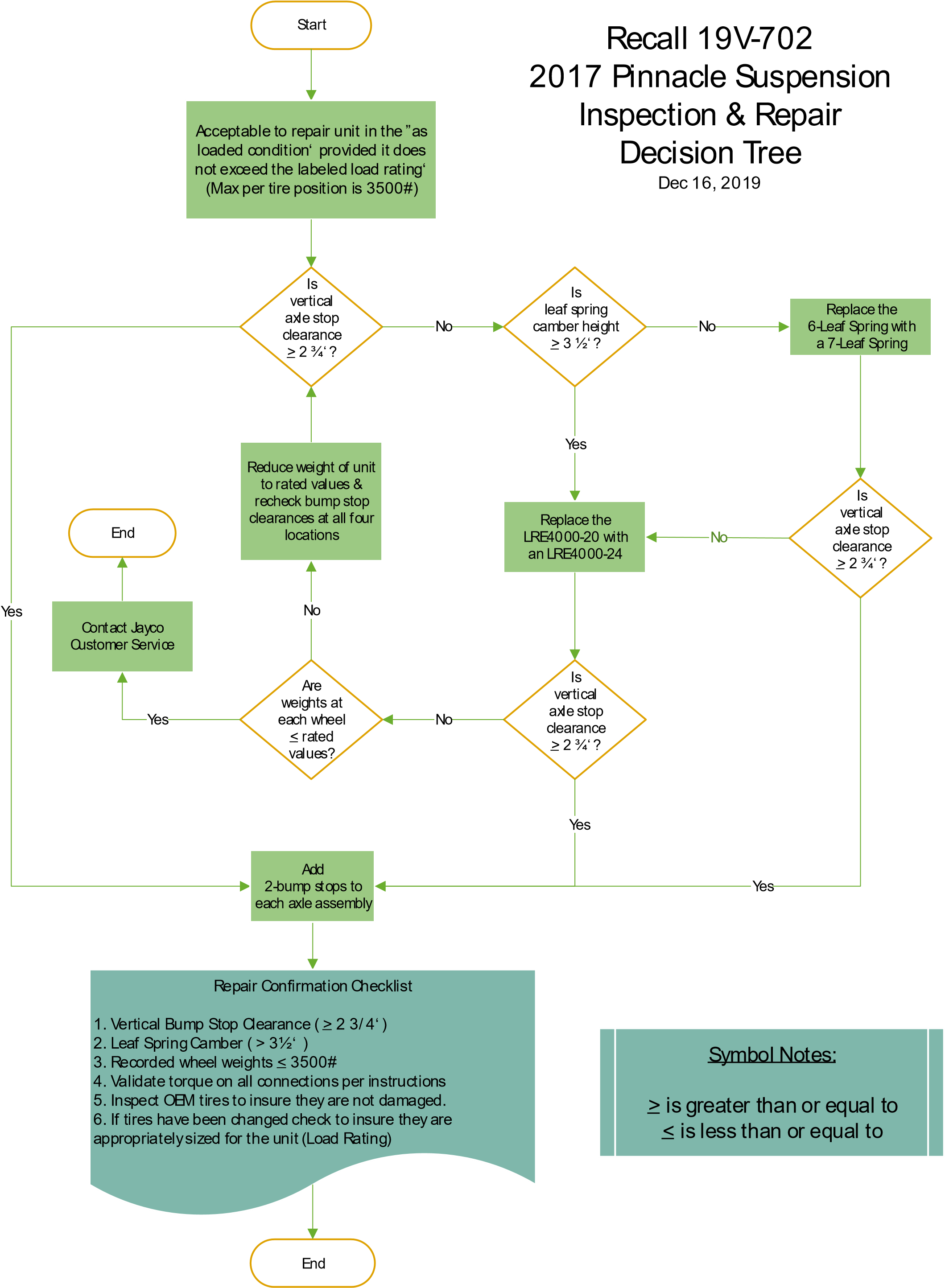
Section I – Step 2: VERTICAL AXLE TRAVEL USING A GAUGE BLOCK
STEP 2:
- Inspect the vertical axle travel distance by placing the 2 ¾” gauge block (from the kit) between the top of the axle tube and the bottom of the 2”x 3” hanger tube as shown in Fig. 2. Repeat inspection at the four (4) axle locations. Write Pass or Fail in the space provided ion the inspection sheet (page 3 of this document).
- PASS: Gauge block fits in the space between axle tube and hanger tube at all four (4) axle locations. GO TO STEP 5.
- FAIL: IF THE GAUGE BLOCK FAILS TO FIT IN ONE OR MORE OF THE FOUR (4) LOCATIONS GO TO STEP 3.
NOTE: The gauge block measurement method shown in figure 2 may need repeated after STEP 3, and again after STEP 4 depending on the components changed.
Section 1-Step 3: INSPECT LIPPERT STEEL LEAF SPRINGS
STEP 3: PARTS KIT 19V-702B MAY BE REQUIRED
- Count the number of leaves that make up the leaf spring (6 or 7).
- Record this number on the inspection sheet (page 3 of this document). Enter the number under the “AS FOUND” section.
FIG 3:
- Place a 28 inch long steel straight edge so it rests on top of the spring tie plate.
- Steel straight edge needs to be 28 inches long so it can balance on the spring tie plate and extend out to the end of each spring to make measuring easier.
FIG 4:
- Measure the vertical distance between the bottom of the straight edge, and the bottom of the upper shackle bolt threads (located at the equalizer) (between arrows in photo).
- Measure this dimension on ALL
- Record dimensions for all springs on the inspection sheet (page 3 of this document) under “AS FOUND” section.
FIG 5:
- Measure the vertical distance between the bottom of the straight edge, and the bottom of the spring hanger bolt thread section (between arrows in the photo).
- Measure this dimension on ALL
- Record dimensions for all springs on the inspection sheet (page 3 of this document) under “AS FOUND” section.
- These two dimensions will give you the approximate vertical distance from the spring eye to the tie plate. This is how the flatness of the spring under load is determined.
- PASS: If all of the leaf springs measurements were greater than 3-1/2 inches, but the gauge block fails to fit into the space between the axle tube and the hanger tube (Fig 2), in one or more of the 4 axle locations…GO TO STEP 4.
- FAIL: If ANY of the leaf springs measurements are less than 3-1/2 inches, ALL (4) leaf springs will need replaced.
- Remove the 6-leaf spring and replace with a 7-leaf springs in accordance with the instructions from Lippert Components, Inc (the axle manufacturer) found on pages 10 through 19 of these instructions.
Repair inspection – After ALL leaf springs are replaced you will need to recheck the clearance between the axle tube and the hanger tube (Fig 2), using the SAME gauge block provided in the kit.
- PASS: Recheck spacing using the gauge block and if it now fits between the axle tube and the hanger tube (in all 4-locations), record results in the “As-Repaired section of the inspection sheet (page 3 of this document), THEN PROCEED TO STEP 5.
- FAIL: If after replacing the springs, the gauge block fails to fit between the axle tube and the hanger tube in any or the 4 locations, THEN PROCEED TO STEP 4.
Section 1-Step 4 RUBBER SHEAR SPRING INSPECTION
STEP 4: PARTS KIT 19V-702C MAY BE REQUIRED
4.1 Inspect the LRE 4000-20 rubber shear spring for damage according to the MORryde inspection instructions (page 20 of this document).
- PASS: If there is no damage to the 4000-20 rubber shear spring, GO TO STEP 4.2.
- FAIL: If the 4000-20 rubber leaf spring has damage, replace both spring blocks with the LRE 400024 rubber shear springs from the kit. Installation shall be in accordance with the MORryde instructions (page 21-27 of this document). Refer also to the LRE Suspension System Owner’s Manual from MorRyde.
4.2 If the leaf spring measurements were correct (greater than 3-1/2 inches) but the 2 ¾” gauge block did not fit between the axle tube and the hanger tube, then the MORryde Rubber Shear Spring requires replacement.
- Remove the MORryde LRE 4000-20 rubber shear springs and replace them with the LRE 4000-24 rubber shear springs. Installation shall be in accordance with the instructions from MORryde instructions (page 21 – 27 of this document). Refer also to the LRE Suspension System Owner’s Manual from MORryde.
- After replacing both rubber shear springs, recheck the axle vertical clearance (Step #2) using the gauge block provided (fig 2). Write Pass or Fail in the “As-Repaired” section of the inspection sheet (page 3 of this document).
- PASS: if the clearance is now sufficient for the gauge block to fit between the axle tube and the hanger tube, THEN PROCEED TO STEP 5.
- FAIL: if the gauge block still fails to fit between the axle tube and the hanger tube (after replacing the leaf springs and the rubber shear springs), you will need to call Jayco Customer Service for further information on how to evaluate this unit.
Section II-Step 5 INSTALLATION OF RUBBER BUMP STOPS (4 TOTAL)
STEP 5: PARTS KIT 19V-702A IS REQUIRED ON ALL UNITS
- Install the rubber bump stops ONLY if the gauge block has successfully fit into the space between the axle tube and the hanger tube behind each wheel, FOUR (4) locations. Reference (Fig 2).
FIG 6:
- Bump Stops (4 per unit).
- Mounting hardware for one bump stop: two 5/16-18 x 5” Gr5 hex bolts, two 5/16 Gr5 flat washers, two 5/16 Gr5 lock washers, and two 5/16-18 Gr5 hex nuts.
FIG 7:
- Position the bump stop over the top of the axle between the spring hanger U-bolts.
- Spring pack will fit in the notches on each leg of the bump stop bracket.
FIG 8:
- Install two 5/16-18 hex bolts through the holes in the bump stop bracket. Place a flat washer, lock washer and nut on each of the bolts.
- Torque to 10-12 Ft/lbs. (nuts should be tightened together) FIG 9:
- Completed bump stop for one axle location.
- Repeat installation process at all three (3) remaining wheel locations.
REFERENCE SECTION: SUGGESTED TOOL LIST FOR CHANGING THE STEEL LEAF SPRINGS & RUBBER SHEAR SPRINGS
- The photo above shows the following tools:
- ½ inch drive Adjustable Torque wrench (zero – 50 Ft/lbs.) (not shown)
- ½ inch ratchet
- 3/8 inch ratchet with 16mm socket
- Punch (approximately 3/8” diameter)
- Small Sledge hammer
- 28” long steel straight edge
- Impact driver with following ½” drive impact sockets: 11/16, 13/16, 14mm, 15mm, 17mm, 19mm
- Screw gun with 6” long 3/8” nutsetter bit (or standard 3/8” nutsetter bit with 6” bit extension)
- Drill with a 3/16” drill bit
- Tape Measure
- Mechanics Creeper
- Grease Gun with a tube of Wheel bearing grease Jayco p/n 0230435
- Lippert Manuals:
- Wet Bolt Installation (p/n ccd 0002018)
- Axle and Suspension Installation (p/n ccd 0001412)
- Trailer Axle Owner Manual 2K-7K
REFERENCE SECTION: PHOTOGRAPHS FOR STEEL LEAF SPRING KIT, RUBBER SHEAR SPRING KIT & RUBBER BUMP STOP KIT
RUBBER BUMP STOP 19V-702A
Required on ALL Units
RUBBER SHEAR SPRING
& OWNERS MANUAL 19V-702C
Required based upon Inspection results
STEEL LEAF SPRINGS 19V-702B
Required based upon inspection results
The photos above show suspension component replacement
TI-345
LEAF SPRING REPLACEMENT ON AN EXISTING AXLE BEAM
AXLES AND SUSPENTION
Purpose
This document outlines the process for replacing the double-eye leaf spring components on an existing axle beam assembly. The following procedure is applicable for both underslung—when the leaf spring is mounted, or “slung”, under the axle—and overslung—when the leaf spring is mounted, or “slung”, over the axle (Fig. 1).
NOTE: Images used in this document are for reference only when assembling, installing and/or operating this product. Actual appearance of provided and/or purchased parts and assemblies may differ.
Safety
Read and understand all instructions before installing or operating this product. Adhere to all safety labels.
WARNING
The trailer MUST be supported per manufacturer’s recommendations before working underneath. Failure to do so may result in death, serious personal injury, severe product and/or property damage.
WARNING
Always lift the trailer by its frame and never by its axle or suspension. Axle and suspension components are not designed, or rated, for the dead weight, point-of-contact loads that the trailer’s frame is. Do not go under the railer unless it is supported by appropriately rated jack stands.
Improperly supported trailers can collapse, causing possible serious personal injury or death.
CAUTION
Moving parts can pinch, cut or crush. Keep clear and use caution.
CAUTION
Wear appropriate personal protective equipment (PPE) when performing service or maintenance operations. Always wear eye protection when servicing trailer axles, brakes, hubs, springs and wheels. Not using PPE may result in personal injury.
Resources Required
- 1 -2 persons, depending on task
- Floor jacks
- Jack stands Torque wrench (ft-lb)
- Pneumatic air or impact gun
- Assorted deep well sockets
- Hammer or mallet
- Torque wrench (ft-lb)
Replacement Procedure
1. Using floor jacks, lift the frame slightly and place properly-rated jack stands under the axles (Fig. 2) so the shackle bolts can be driven out with a hammer.
2. Place a suitable block under the axle tube near the area to be repaired.
NOTE: The block acts as a support for the weight of the axle only, allowing suspended system components to be serviced or replaced freely. Multiple axle trailers MUST have the weight of each axle properly supported before disassembly of any suspension system components.
3. Remove tires and wheels—curbside and roadside—from the axle (Fig. 3) with the affected leaf spring. 4.
4. Set wheel and lug nuts (Fig. 3) aside for later installation.
5. Inspect axle/brake assembly electrical wiring and/or hydraulic hoses for length. If lines are too short to allow lowering the axle, disconnect lines before lowering.
NOTE: Make sure electrical power is off and hydraulic system has been de-energized before disconnecting lines.
6. With an impact gun or an appropriate wrench, loosen the nuts on the leaf spring bolts and the shackle bolts (Fig. 4).
NOTE: Hold the head of the bolts with a wrench.
7. Remove the nuts from the leaf spring bolts and the shackle bolts.
8. Drive out the leaf spring bolts with a mallet or hammer until they unseat from their hanger.
A. Inspect the threaded end of the bolts for damage to the threads.
B. If threads are damaged, replace bolts. Otherwise, set bolts and nuts aside for later installation.
9. Drive out the shackle (wet) bolts of the shackle link assemblies with a mallet or hammer until they unseat from their leaf spring and equalizer.
A. Inspect the threaded end of the shackle (wet) bolts for damage to the threads.
B. If threads are damaged on one or both bolts, replace shackle link assembly. Otherwise, set shackle link assemblies, shackle links and nuts aside for later installation.
NOTE: At this point in the installation, LCI recommends inspecting the equalizer shackle links. If the shackle links are worn, LCI recommends replacing them.
NOTE: Shackle links MUST be reinstalled using the same shackle orientation used previously.
10. Adjust the floor jacks so the jack stands can be removed from under the axle.
11.0Using the floor jacks, lower the axle of the leaf spring being replaced.
12. Position and orient the new leaf spring (Fig. 5) underneath the trailer to help expedite installation.
13. After the axle and leaf springs have been lowered from the chassis hangers and shackle links:
A. Remove U-bolt nuts (Fig. 6A) from the affected leaf spring.
B. Remove U-bolts (Fig. 6B) and tie (spring) plate (Fig. 6C) from the axle (Fig. 6E) holding the affected leaf spring (Fig. 6D).
C. Set U-bolts, nuts and tie (spring) plate aside for later installation.
D. Set removed leaf spring aside. Do NOT reuse affected leaf spring.
14. Place the new leaf spring (Fig. 6) onto the axle with the leaf spring clip pointing towards the front of the trailer. Make sure spring center bolt engages the center hole of the tie (spring) plate.
15. Position U-bolts and tie (spring) plate on the axle (Fig. 7).
A. Install washers, if equipped, and hand-start nuts. B. Hand-tighten nuts until snug (Fig. 7).
B. Verify the following:
C. Center bolt is engaged in tie (spring) plate (Fig. 7). Leaf spring is square to the axle (Fig. 7).
I. Center bolt is engaged in tie (spring) plate (Fig. 7).
II. Leaf spring is square to the axle (Fig. 7).
III. U-bolts are straight up and down and not splayed in or out.
IV. U-bolts have approximately the same amount of thread sticking out of each nut.
16. Progressively tighten tie (spring) plate nuts in a criss-cross pattern, in the order given (Fig. 8), until the final torque is obtained. Refer to Spring Axle Torque Specifications chart for bolt torque requirements.
| Spring Axle Torque Specifications | ||
| Bolt Type | Axle Capacity | Torque |
| 3/8″ U-Bolt Nuts | 2K | 35 ft-lbs |
| 1/2″ U-Bolt Nuts | 3.5K | 50 ft-lbs |
| 9/16″ U-Bolt Nuts | 5.2K | 65 ft-lbs |
| 9/16″ U-Bolt Nuts | 6-8K | 90 ft-lbs |
| Spring Eye, Equalizer and Shackle Nuts | All Double Eye | 30-50 ft-lbs |
17. Verify the following:
A. Leaf spring is square to the axle.
B. Tie (spring) plate is flat against leaf spring.
C. U-bolts are straight.
D. U-bolts have approximately the same amount of thread sticking out of each nut.
E. All nuts are torqued.
18. Use floor jacks and jack stands to raise axle assembly into position for reinstallation to the trailer’s frame, do as follows:
A. Reinstall previously removed leaf spring hanger and shackle bolts and nuts.
B. When installing wet bolts, use a steel tube and hammer to drive in wet bolts to prevent damage to the grease fitting.
C. Refer to Spring Axle Torque Specifications chart for bolt torque requirements.
NOTE: Hold the head of the bolts with a wrench.
D. If installing new or previously removed wet bolts, apply new grease. Use NLGI code GC-LB.
E. Reconnect any disconnected electrical lines and/or hydraulic hoses (step 5).
NOTE: If reconnecting hydraulic hoses, make sure all hydraulic lines are purged of air.
19. Reinstall previously removed tires, wheels and lug nuts (steps 3 and 4) onto the axle (Fig. 3).
A. Start all wheel lug nuts by hand to prevent cross-threading.
B. Continue to hand-tighten wheel lug nuts in the sequential pattern shown in figure 9.
C. After wheel lug nuts are fully hand-tightened, torque nuts in stages and in the sequential pattern shown in figure 9.
D. Torque wheel lug nuts to the torque values listed in the Wheel Torque Requirement Chart.
| Wheel Torque Requirement Chart | ||||
| Wheel Size | Stud Size | Torque Sequence | ||
| 1 st Stage | 2nd Stage | 3rd Stage | ||
| 14″ | 1/2″ | 20-25 ft-lbs | 50-60 ft-lbs | 90-1 20 ft-lbs |
| 1 5″ | 1/2″ | 20-25 ft-lbs | 50-60 ft-lbs | 90-1 20 ft-lbs |
| 16″ | 1/2″ | 20-25 ft-lbs | 50-60 ft-lbs | 90-1 20 ft-lbs |
| 16.5″ x 6.75″ | 1/2″ | 20-25 ft-lbs | 50-60 ft-lbs | 90-1 20 ft-lbs |
| 16″ | 9/16″ | 20-25 ft-lbs | 60-70 ft-lbs | 120-130 ft-lbs |
| 16.5″ x 6.75″ | 9/16″ | 20-25 ft-lbs | 60-70 ft-lbs | 120-130 ft-lbs |
| 16″ Dual and 17.5″ Cone Nut | 5/8″ | 50-60 ft-lbs | 100-120 ft-lbs | 190-210 ft-lbs |
| 16″ Dual and 1 7.5″ Flange Nut | 5/8″ | 50-60 ft-lbs | 1 50-200 ft-lbs | 275-325 ft-lbs |
| 14.5″ Demount | 1/2″ | Tighten sequentially to 85-95 ft-lbs | ||
20. The leaf spring replacement procedure is now complete.
As a supplier of components to the RV industry, safety, education and customer satisfaction are our primary concerns. Should you have any questions, please do not hesitate to contact us at (574) 537-8900 or by email at customerservice@lcil .com. Self-help tips, technical documents, product videos and a training class schedule are available at lcil .com or by downloading the MyLCI app.
Rev: 12.09.19
CCD-0003592
TI-124
WET BOLT INSTALLATION
AXLES AND SUSPENSION
Recommended Tools:
- Alignment Tool- Spud Wrench or Bull Pin or similar
- Floor Jack
- Grease Gun
- Hammer
- Jack Stands
- Pneumatic Impact Gun w/ 7/16” Impact Socket
*Reference TI-083 for standard chassis blocking*
1. Using jack stands to support chassis, support axle for safe disassembly of axle bolts and After removing axle bolts, inspect spring eyes for brass bushings. Change if needed by using the following procedure:
A. Place brass bushing on an appropriately sized punch. An appropriate sized punch will allow the bushing to slip onto the shaft, but not slide off the other end.
B. Insert end of punch into spring eye.
C. Drive old bushing out with hammer.
D. As the old bushing is driven out, the new bushing will be inserted into the spring eye.
E. The new bushing should be seated as shown (See 1).
2. Replace standard mounting hardware, one at a time, with wet bolts and 7/16” locking flange nuts (See Fig. 2). Insert the wet bolts with the grease zerks on the inside of the spring hangers into the axle mounting holes as shown (See Figs. 4 & 5). The serrations under the head of the wet bolt should be fully inserted into the brass bushing.
NOTE: Grease hole should be positioned at 3 or 9 o’clock. If the grease holes are not installed properly, the weight of the chassis will prevent the grease from fully lubricating the brass bushings (See Fig. 3 for location of grease hole).
Part Numbers:
127846
163692
3. Tighten locking flange nuts to shoulders of wet bolts. If the serrations under the head of the wet bolt are not fully inserted into the brass bushing, carefully tap the wet bolt into position with a rubber mallet or similar tool. Care should be taken not to damage the grease zerks.
4. Apply enough grease to fully lubricate the brass Typically, two squirts from a manual grease gun are sufficient.
5. Reconnect electric brakes, if applicable.
6. Remount wheels.
As a supplier of components to the RV industry, safety, education and customer satisfaction are our primary concerns. Should you have any questions, please do not hesitate to contact us at (574) 537-8900 or by email at customerservice@lci1.com. Self-help tips, technical documents, product videos and a training class schedule are available at lci1.com or by downloading the MyLCI app.
Rev: 08.24.18
CCD-0002018
REPLACING THE LRE 4000-20 RUBBER SHEAR SPRINGS
TOOLS REQUIRED:
- Jack stands (minimum of two (2), four (4) are preferred).
- Floor jack (minimum of one (1), two (2) are preferred)
- 9/16” wrench and socket
- 5/8” wrench
- 11/16” socket
- 13/16” wrench
- Ratchet or Impact gun
- Torque wrench (Ft/lbs.)
WARNING: THE UNIT SHOULD BE ON A LEVEL SURFACE. DO NOT ATTEMPT THIS INSTALLATION ON
SOFT GROUND OR AN UNEVEN SURFACE. FOLLOW YOUR TRAILER MANUFACTURER’S SPECIFICATIONS ON LIFTING AND SUPPORTING OF THE UNIT. PROPER CAPACITY JACKS AND SUPPORTS SHOULD BE USED AT ALL TIMES. DO NOT SUBSTITUTE BLOCKS OR OTHER ITEMS FOR JACKS.
NOTE: These instructions are based on lifting and supporting the entire weight of the trailer at once. This installation can be done by only supporting one side of the trailer at a time, however the level of difficulty will increase. The best practice for this installation is the support the entire weight of the unit by jack stands/supports at one time.
- The trailer should be supported safely. This should be done by placing jack stands directly to the frame towards the front and the rear of the RV equally balancing the weight of the unit on all four points. The front landing gear may be used if only two jack stands are available. Be sure to raise the trailer to where all four tires are off the ground and the wheels can spin freely without resistance.
- Beginning on either side of the LRE, use the 11/16” socket and 13/16” wrench to remove the four nuts fastening the shackle links to the LRE and leaf springs. DO NOT REMOVE THE SHACKLE LINKS.
- Use the floor jack to support the front axle, gently raise the axle to remove weight from the LRE.
NOTE: if you are using two floor jacks, duplicate the process of Step 4 for the rear axle.
- Remove the shackle links from the front side of the LRE.
- Release the weight from the floor jack and repeat the process for the rear axle. Once finished, release the floor jack lowering the axle down. Both axles will be disconnected from the LRE at this time.
- Using the 9/16” socket and wrench, remove the eight nuts and bolts holding the LRE rubber shear spring in the LRE hanger box. There are 4 bolts on each side of the hanger box. Once all eight are removed, lower the rubber shear spring out of the hanger box.
(refer to exploded view on page 27)
- Using the 11/16” socket and 5/8” wrench, remove the 4 nuts and bolts holding the LRE shackle brackets to the rubber shear spring.
- Reinstall the LRE shackle brackets onto the new rubber shear spring (LRE 4000-24) using the 7/16” hardware and the 11/16” socket and 5/8” wrench.
TORQUE TO 45 FT LBS.
- Position the rubber shear spring in the LRE hanger box so that the center plate is lower than the outer plates and fasten into place using the 3/8” hardware and the 9/16” socket and wrench.
TORQUE TO 40 FT LBS.
- Using the floor jack, raise the front axle up to where the leaf spring eye is in position for the shackle links to be installed. Insert the shackle link assembly, then place the loose shackle link on the bolts and reinstall 7/16” flange nuts using the 11/16” wrench and 13/16” socket.
TORQUE TO 50 FT LBS.
- Repeat Step 11 to attach the shackle links to the rear side of the rubber shear spring.
- Repeat Steps 3 through 12 for the opposite side of the trailer.
- Reinstall the wheels on both sides of the trailer. Lower the trailer to the ground and remove the jack stands. Torque the lug nuts to manufacturer specifications.
| Parts List | ||
| ITEM | QTY | DESCRIPTION |
| 1 | 1 | HANGER BOX |
| 2 | 4 | SHACKLE BRACKET |
| 3 | 4 | 7/16-14 X 1.25 HEXHEAD CAPSCREW |
| 4 | 8 | 3/8-16 X 1 HEXHEAD CAPSCREW |
| 5 | 8 | 3/8-16 HEXNUT |
| 6 | 4 | 7/16-14 HEXNUT |
| 7 | 1 | SHEAR SPRING |
Safety Recall: 19V-702
December 2019
IMPORTANT SAFETY RECALL
This Notice Applies to Your Recreational Vehicle «vin»
Dear Valued Customer:
This notice is sent to you in accordance with the National Traffic and Motor Vehicle Safety Act.
Jayco has decided that a defect, which relates to motor vehicle safety, exits in ALL Model Year 2017 Pinnacle fifth wheels.
| Reason for this recall | Under certain conditions, the suspension system may allow a tire to make contact to the wheel well and surrounding structure of the fifth wheel. This may cause damage to a tire, premature tire wear and cause handling issues that could lead to increased risk of a crash. |
| Recall Remedy | Inspection of the suspension to determine the current condition of the leaf springs, rubber equalizer and bump stop clearance. Based on the inspection results, replacement of a leaf spring and/or a rubber equalizer may be required. Additionally, installation of rubber bumper stops to the underside of the leaf spring hanger tube is required on all affected fifth wheels. |
| What we need you to do | Please contact an authorized Dealer as soon as possible to schedule an appointment. The Recall Remedy is free of charge and depending on inspection results, may take approxiatmeitly 3-4 days to complete. |
If you had this repair completed prior to receipt of this recall notice, you may be eligible to receive reimbursement for the cost of obtaining a pre-notification remedy of the problem associated with this recall.
If you take your recreational vehicle to your dealer on the agreed service date and the dealer does not remedy this condition on that date or within three (3) days, please contact our Customer Service Department at 800-283-8267. If after contacting your dealer and Customer Service you are not able to have the safety defect remedied without charge and/or within a reasonable time, you may wish to submit a written complaint to the Administrator, national Highway Traffic Safety Administration, 1200 New Jersey Avenue, SE., Washington, DC 20590; or call the toll-free Vehicle Safety Hotline at 1-888-3274236 (TTY: 1-800-424-9153): or go to https://www.safercar.gov. Federal regulations require that any vehicle lessor receiving this recall notice must forward a copy of this notice to the lessee within ten days.
We certainly regret this inconvenience; however, your safety is our most important priority.
Sincerely,
Jayco Towables
Safety Recall: 19V-702 2019-551
December 2, 2019
IMPORTANT SAFETY RECALL-PRE- NOTIFICATION
This Notice Applies to Your Recreational Vehicle Unit
Dear Valued Customer:
This notice is sent to you in accordance with the National Traffic and Motor Vehicle Safety Act. Jayco has decided that a defect, which relates to motor vehicle safety, exits in certain Model Year 2017 Pinnacle fifth wheels.
| Reason for this recall | Under certain conditions, the suspension system may allow tire contact to the wheel well and surrounding structure of the fifth wheel. This may cause damage to the tire, premature tire wear and/or cause handling issues that could lead to increased risk of a crash. |
| Recall Remedy | Inspection and repair of the suspension system components between the axle and frame. While the design for the remedy is complete, the required parts are still under validation by Jayco and involved suppliers. Subsequently, the parts are not available at the time of this notification. Jayco will release a Second Recall Notice to you by January 1, 2020 to announce the repair instructions and parts availability. |
| What we need you to do
|
CAUTION: Until the Recall Remedy is completed, please be aware of the weight rating for your fifth wheel and ensure the actual weight of your fifth wheel is within those labeled values. Also, always inspect and validate the condition of your tires prior to every trip. |
If you have questions regarding this Recall pre-notification, please contact Customer Service Department at 800-283-8267. Federal regulations require that any vehicle lessor receiving this recall notice must forward a copy of this notice to the lessee within ten days.
We certainly regret this inconvenience; however, your safety is our most important priority.
Sincerely,
Jayco Towables
1 Affected Product
Vehicle
| MAKE | MODEL | YEAR |
| JAYCO | PINNACLE | 2017 |
12 Associated Documents
Recall Quarterly Report #3, 2020-2
RCLQRT-19V702-2543.PDF 211.306KB
 Loading...
ISSUED Interim Owner Notification Letter(Part 577)
RIONL-19V702-8420.pdf 50.752KB
Loading...
Recall 573 Report – Amendment 4
RCLRPT-19V702-1100.PDF 213.981KB
Loading...
Recall Quarterly Report #1, 2019-4
RCLQRT-19V702-4061.PDF 211.114KB
Loading...
Recall Quarterly Report #2, 2020-1
RCLQRT-19V702-5246.PDF 211.215KB
Loading...
Recall 573 Report – Amendment 3
RCLRPT-19V702-6678.PDF 213.43KB
Loading...
Recall 573 Report – Amendment 2
RCLRPT-19V702-8638.PDF 214.019KB
Loading...
Recall 573 Report – Amendment 1
RCLRPT-19V702-6626.PDF 212.281KB
Loading...
Remedy Instructions and TSB
RCRIT-19V702-5167.pdf 2435.141KB
Loading...
Defect Notice 573 Report
RCLRPT-19V702-7736.PDF 212.115KB
Loading...
ISSUED Owner Notification Letter(Part 577)
RCONL-19V702-3328.pdf 51.195KB
Loading...
Recall Quarterly Report #4, 2020-3
RCLQRT-19V702-9504.PDF 211.412KB
Loading...
Latest Recalls Documents
https://www-odi.nhtsa.dot.gov/acms/cs/documentList.xhtml?docId=19V702&docType=RCL
TI-124
CCD-0002018
Loading...
NHTSA ID Number: 10170025
Manufacturer Communication Number: TI-345
Summary
How to replace a leaf spring on an existing axle beam
1 Affected Product
Equipment
| BRAND | PART NO. | PRODUCTION DATES |
| EQUIPMENT | EQUIPMENT | |
1 Associated Document
Manufacturer Communications
TI-345
https://www.nhtsa.gov/recalls?nhtsaId=10170025
MC-10170025-0001.pdf 1963.683KB
Loading...
TI-345
Loading...
| “This site contains affiliate links for which OEMDTC may be compensated” |

- Specs: 3,500 lbs Idler Trailer Axle (Capacity 3.5K), 5 Lug, Tube: 2 3/8"
- High Strength Straight Steel Axle Tube
- Axle comes fully assembled, so all you'll have to do is attach the springs, the U-bolt kits, and the tire and wheel assemblies.
- Underslung - Spring seats are welded to the bottom of the axle, which allows for a lower ride height.
- Trailer Axle Design for use on Light Duty Trailers

- EZ Lube Design Removable rubber plug on the hub cap with easy access to a grease-able zerk fitting Grease your axle without pulling off your whole entire hub
- Internal Wiring System To ensure seamless design Protect brake wires from wear and tear
- High Strength Straight Steel Axle Tube Construction to ensure Even Tire Wear A better highway experience
- Underslung - Axle is welded with spring seats on the bottom Allows for lower ride height For optimal usage, use with double eye springs
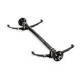
- 72" from Hubface to Hubface and 58" Spring Center to Spring Center.
- Springs are 25 1/4" long and 1 3/4" wide
- 4 Leaf Springs
- 2-3/8" Main Tube
- 5 Lug with a 4 1/2" bolt pattern. 1/2 lug studs.
- Capacity: 2000 lbs, Tube:1-3/4 | 5x4.5 Bolt Pattern
- EZ Lube Design: Removable rubber plug on the hub cap with easy access to a grease-able zerk fitting. Grease your axle without pulling off your whole entire hub.
- Internal Wiring System: To ensure seamless design and protect brake wires from wear and tear.
- High Strength Straight Steel Axle Tube Construction: To ensure even tire wear and a better highway experience.
- Underslung - Axle is welded with spring seats on the bottom: Allows for lower ride height. For optimal usage, use with double eye springs.

- All-in-One Bundle: This 3.5K LD Single Axle trailer kit includes everything you need for a quick and easy installation, such as a 3.5k Idler Axle, double eye hanger kit, 4-Leaf Double Eye Springs, and 2 1.75k U-Bolt Kits
- High Strength Construction - The high strength steel axle tube construction ensures a durable and long-lasting performance for small utility trailers, cargo trailers, ATV trailers, and more
- High-Quality Parts - Made with OEM grade trailer axles and suspension, this kit is packed with high-temp axle grease for reliable performance
- Low Ride Height - With an underslung design, the axle is welded with spring seats on the bottom, allowing for a lower ride height and improved stability
- EZ Lube Design - Removable rubber plug allows for easy access to a grease-able zerk fitting, allowing you to grease your axle without having to remove the entire hub

- Underslung Design - Our trailer axle is underslung and Welded with Spring Seats on the Bottom - Provides a lower ride height for easier loading and unloading of your trailer
- EZ Lube Design - These single trailer axle features a removable rubber plug on the hub cap - allows for easy grease access without the need to remove the entire hub, saving you time and hassle
- Light Duty Trailer Axle - Designed for use on light duty trailers, utility, boat, car haulers, ATV, lawn & landscape, motorcycle, BBQ pit, cargo, enclosed, RV trailers and more
- Internal Wiring System - The trailer axle comes with an internal wiring system that protects brake wires from wear and tear, ensuring a seamless design that is perfect for any trailer type
- 5x4.5 Bolt Pattern - The 5 x 4.5 bolt pattern offers compatibility with a wide range of trailer wheels, providing flexibility and convenience for your trailer setup

- 2,000 lbs capacity
- Stub axles can be bolted (hardware not included) or welded to trailer frame
- 45 degree downward starting angle
- Perfect item to easily build your own custom motorcycle trailer
- Read product description below for more detailed information.

- Complete Rockwell American 3,500 lb Idler Axle - Made in the USA
- 3,500 lb Idler Axle Hubs, Bearings, Lugs & Nuts (2 Year MFG Warranty) & (1) 32 oz Johnson Trailer Parts Insulated Mug
- This Axle Comes with a Superior Powder Coated Finish and Posi-Lube Spindles that Provide Continuous Bearing Protection
- 5 Lug on 4.5 Bolt Pattern (other bolt patterns available - Contact Johnson Trailer Parts)
- Replaces Dexter, Al-ko & TK Trailer Axles. This Axle Kit is Available in the Sizes Shown in the 3rd Picture - Search "Johnson Trailer Parts or Rockwell American" in Amazon Search Bar for more Trailer Parts

- Specs: 3,500 lbs Idler Trailer Axle (Capacity 3.5K), 5 Lug, Tube: 2 3/8"
- High Strength Straight Steel Axle Tube
- Axle comes fully assembled, so all you'll have to do is attach the springs, the U-bolt kits, and the tire and wheel assemblies.
- Underslung - Spring seats are welded to the bottom of the axle, which allows for a lower ride height.
- Trailer Axle Design for use on Light Duty Trailers
Last update on 2024-06-11 / Affiliate links / Images from Amazon Product Advertising API
This product presentation was made with AAWP plugin.