| “This site contains affiliate links for which OEMDTC may be compensated” |
NHTSA ID Number: 10109089
Manufacturer Communication Number: 99931-1579-01
Summary
Assembly and Preperation Manual
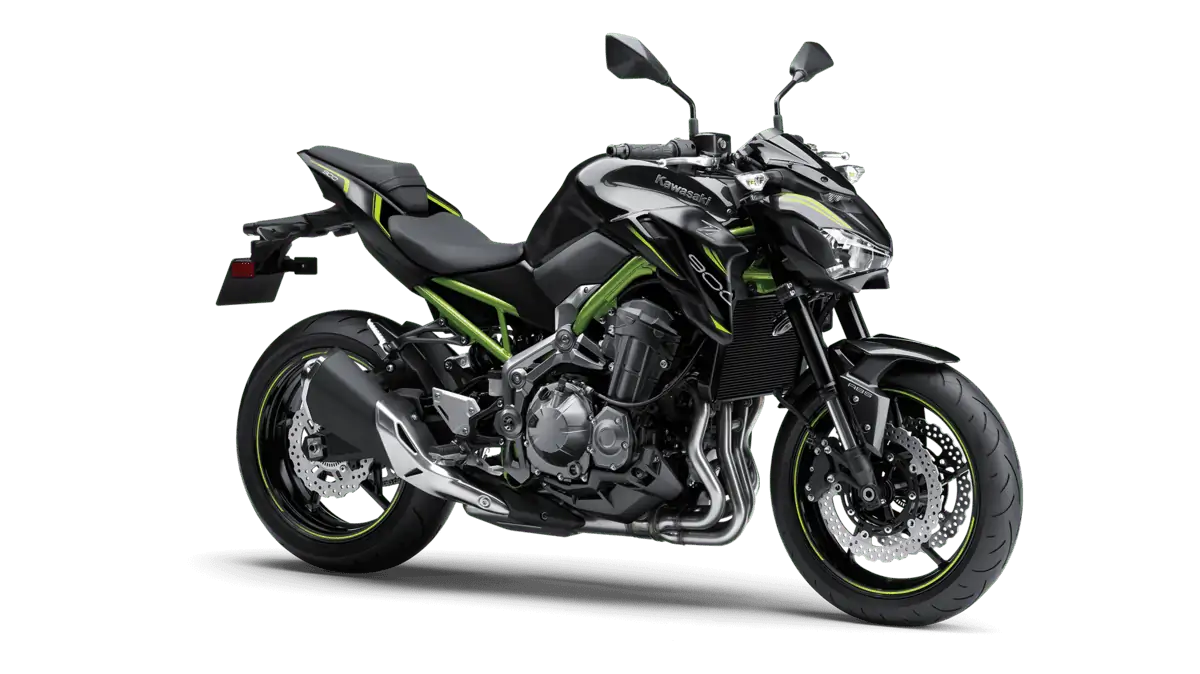
Kawasaki
Z900
Z900 ABS
Motorcycle Assembly and Preparation Manual
Oct., 2016
1 Affected Product
Vehicle
| MAKE | MODEL | YEAR |
| KAWASAKI | ZR900 | 2017 |
1 Associated Document
Manufacturer Communications
Part No.99931-1579-01
https://www.nhtsa.gov/recalls?nhtsaId=10109089
MC-10109089-9999.pdf 4491.946KB
https://static.oemdtc.com/TSB/MC-10109089-9999.pdf
 Loading...

- Formulated with Trizone technology to protect all 3 critical zones: engine, clutch and gearbox
- Race derived technology for maximum engine acceleration
- Extreme high temperature air-cooled performance and water-cooled engine performance
- Excellent shear stability to prevent viscosity breakdown
- Exceeds API SL and JASO MA-2

- 100% Synthetic Ester
- Formulated To Meet The Latest Manufacturers' Specifications
- Improved High Temperature Deposit Protection And Sludge Control
- Ensures Optimum Clutch Performance At Start-Up, Acceleration, And Full Speed
- Standards: Ape Sn, Jasso Ma2

- Optimal lubrication in all operating conditions, ensures low oil consumption
- Very high shear and ageing stability, highest levels of wear protection
- Tested and approved for catalytic converters, optimal engine cleanliness
- Ideally suited for wet clutches
- Specifications and Approvals: API, SM, ACEA A3-04, JASO, MA2
- 100% Synthetic Double Ester
- Designed for highly modified engines
- Electrochemical bonding to metal parts
- Up to 5x higher film strength
- 0% shear loss on Bosch ASTM D6278 test

- Full synthetic 5W-40 diesel engine oil with Triple Protection Plus technology protects against wear, deposits, and oil breakdown
- Improved wear performance with significantly increased level of protection against harmful engine wear (compared to previous generation API CJ-4 engine oils)
- Enhanced fuel economy capability of 1.5% without compromising engine protection or durability (compared to 15W-40 oils)
- Multi-functional dispersant additives provide an enhanced level of protection against the effects of soot, dirt, and other contaminants
- Resists breakdown by heat to provide continuous protection throughout the service interval, and also provides improved low-temperature flow compared to conventional 15W-40 oils


- Optimal lubrication in all operating conditions, ensures low oil consumption
- Very high shear and ageing stability, highest levels of wearing protection
- Tested and approved for catalytic converters, optimal engine cleanliness
- Ideally suited for wet clutches
- Specifications and Approvals: API, SM, ACEA A3-04, JASO, MA2
- XPS synthetic 4-stroke oil is specifically engineered to meet the particular lubrication requirements of Can-Am, Spyder and Sea-Doo vehicles equipped with Rotax 4-TEC 4-stroke engines.
- Powersport formula with premium anti-wear and anti-corrosion additives
- Designed for high-performance off-road, on-road and PWC 4-stroke engines, including turbo or supercharged Powersports engines
- Provides superior engine and transmission protection against rust and corrosion even in extreme conditions
- Ambient temperature operating range: -31°F / 104°F (-35°C / 40°C)
Last update on 2024-06-10 / Affiliate links / Images from Amazon Product Advertising API
This product presentation was made with AAWP plugin.
SEOCONTENT-START
Z900 Z900 ABS Foreword In order to ship Kawasaki vehicles as efficiently as possible, they are partially disassembled before crating. Since some of the most commonly removed parts have a direct bearing on a vehicle’s reliability and safety, conscientious pre-sale assembly and preparation becomes extremely important. Good setup procedures can prevent needless warranty claims and give customers a greater sense of confidence in Kawasaki and their Kawasaki Dealers. This Assembly and Preparation Manual explains step by step procedures of the following items for all Kawasaki Z900 and Z900 ABS. 1. Uncrating 2. Assembly 3. Preparation The selling dealer assumes sole responsibility for any unauthorized modifications prior to sale. Refer to your Service Binder for any Service Bulletins specifying Factory Directed Modifications (Special Claims) which must be performed before the vehicle is ready for sale. Whenever you see the following symbols heed their instructions! Always follow safe operating and maintenance practices. DANGER DANGER indicates a hazardous situation which, if not avoided, will result in death or serious injury. WARNING WARNING indicates a hazardous situation which, if not avoided, could result in death or serious injury. NOTICE NOTICE is used to address practices not related to personal injury. NOTE ○NOTE indicates information that may help or guide you in the operation or service of the vehicle. Kawasaki Heavy Industries, Ltd. accepts no liability for any inaccuracies or omissions in this publication, although every possible measure has been taken to make it as complete and accurate as possible. All procedures and specifications subject to change without notice. © 2016 Kawasaki Heavy Industries, Ltd. Oct., 2016 Table of Contents Uncrating 3 Opening Crate . 3 Parts Check. 5 Assembly 8 Handlebar Weight 8 Clutch Cable 8 Frame Slider (Equipped Model) 8 Frame Cover . 9 Rear View Mirrors 9 Windshield (Equipped Model) . 10 Front Axle Slider (Equipped Model) 10 Single Seat Cover (Equipped Model) 11 French Label (For Canada Model) 11 Brake Disc Cleaning 12 Preparation . 12 Battery Service 12 Coolant 16 Front Brake 17 Rear Brake 18 Clutch Lever and Cable. 20 Drive Chain 20 Front Fork 22 Rear Shock Absorber 22 Tire Air Pressures 23 Fuel . 23 Engine Oil (4-stroke) . 23 Throttle Grip and Cable . 24 Rear Brake Light Switch 25 Idle Speed Adjustment 26 Headlight Aim 26 Digital Meter 27 Fastener Check . 28 Standard Torque Table 30 Test Ride the Motorcycle . 30 A & P Check List . 30 UNCRATING 3 Uncrating Opening Crate WARNING Crates have sharp edges and may have nails or screws that can cause cuts and injury. Always wear protective gloves, boots and eye protection when uncrating to prevent injury. WARNING The steel crate panel plates and fasteners have sharp edges. Always wear protective gloves, boots and eye protection when uncrating to prevent injury. •Clear a space about 6 m (20 ft) square to give yourself plenty of space to work. •Place the crate upright on its base. •Remove the cardboard cover. •Remove the parts box. NOTICE When removing the crate bracket from the motorcycle, be careful not to drop any parts or the bracket onto the fuel tank and other components, and not to scratch the fuel tank or other components with the crate bracket. •Take out all the bolts and screws and remove the top and sides of the crate. •Loosen the front axle holding nuts. •Remove the left front support bracket bolt and discard it. •Remove the front axle holding nuts, left front support bracket and rubber washer, and discard them. A. Front Axle Holding Nuts B. Left Front Support Bracket C. Left Front Support Bracket Bolt D. Rubber Washer •Remove the right front support bracket bolt and discard it. •Remove the front axle holding bolt, right front support bracket and rubber washer, and discard them. A. Front Axle Holding Bolt B. Right Front Support Bracket C. Right Front Support Bracket Bolt D. Rubber Washer •Cover the clean closes on the front footpegs to prevent damage. •Remove the lower support bracket bolts on the left and right sides and discard them. •Lift the vehicle upward about 10 cm (4 in.) and remove the lower support brackets and rubber washers on the left and right sides. Roll the vehicle off the crate base. 4 UNCRATING A. Lower Support Bracket Bolts B. Lower Support Brackets C. Rubber Washers NOTICE When rolling the vehicle off the crate base, sharp edges on the crate can cut or damage tires. Cover sharp edges with waste cloth for tire protection as necessary. UNCRATING 5 Parts Check •Open the parts box, and check the parts against the illustrations. There may be minor differences between these illustrations and the actual vehicle parts. In the following charts under Remarks, D = diameter in millimeters, and L = length in millimeters. No. Part Name Qty Remarks 1 Right Handlebar Weight 1 2 Weight Bolt with a Non-permanent Locking Agent 1 D = 8, L = 30 3 Left Rear View Mirror 1 4 Right Rear View Mirror 1 5 Left Frame Cover 1 6 Right Frame Cover 1 7 Socket Bolt 4 D = 5, L = 12 8 Washer 4 D = 5.2 9 Pad 2 10 Battery Electrolyte, FTX9-BS 1 12 V 8 Ah 11 Owner’s Manual 1 6 UNCRATING UNCRATING 7 No. Part Name Qty Remarks (Equipped Model only) 1 Windshield 1 2 Socket Bolt 4 D = 5, L = 20 3 Washer 4 4 Wellnut 4 D = 5 5 Left Frame Slider 1 6 Right Frame Slider 1 7 Left Bracket 1 8 Right Bracket 1 9 Socket Bolt with a Non-permanent Locking Agent 2 D = 6, L = 12 10 Collar 2 D = 10.5, L = 8.1 11 O-ring 2 D = 15.8 × 2.4 12 Flange Bolt 2 D = 6, L = 16 13 Collar 2 D = 6.5, L = 8.1 14 O-ring 2 D = 11 × 2.4 15 Left Frame Slider Cover 1 16 Right Frame Slide Cover 1 17 Socket Bolt 4 D = 5, L = 16 18 Wellnut 4 D = 5 19 Cap 2 20 Bolt 1 D = 10, L = 300 21 Washer 2 22 Slider 2 23 Left Collar 1 L = 25.5 24 Right Collar 1 L = 29.5 25 Nut 1 26 Single Seat Cover 1 (French Label for Canada Model only) 27 French Table 1 28 Important Drive Chain Information 1 29 Tire and Load Data 1 30 Vehicle Emission Control Information 1 8 ASSEMBLY Assembly Handlebar Weight •Install the handlebar weight on the right end of the handlebars with the bolt (D = 8, L = 30) with a non-permanent locking agent and tighten them. A. Handlebar Weight (Right) B. Bolt (D = 8, L = 30) Clutch Cable •Apply a light coat of grease on the clutch inner cable. •Line up the slots on the clutch lever and adjuster. •Fit the tip of the clutch inner cable into the lever socket, slide the inner cable through the slots, and release the outer cable into the adjuster. A. Clutch Cable B. Adjuster C. Cable Tip D. Clutch Lever Frame Slider (Equipped Model) •Remove the middle front engine mounting bolt (D = 10, L = 65) and collar (D = 10.5, L = 34). A. Middle Front Engine Mounting Bolt (D = 10, L = 65) B. Collar (D = 10.5, L = 34) •Install the frame cover (see in the Frame Cover section). •Install the bracket with the bolt (D = 6, L = 12) with a non-permanent locking agent and tighten them. A. Frame Cover B. Bracket C. Bolt (D = 6, L = 12) •Install the collar (D = 10.5, L = 34) and frame slider. •Install the collar, O-ring and frame slider bolt (D = 6, L = 16). •Install the collar, O-ring and tighten themiddle front engine mounting bolt (D = 10, L = 65). Torque: 44 N·m (4.5 kgf·m, 32 ft·lb) ASSEMBLY 9 A. Collar (D = 10.5, L = 34) B. Frame Slider C. Frame Slider Bolt (D = 6, L = 16), Collar and O-ring D. Middle Front Engine Mounting Bolt (D = 10, L = 65), Collar and O-ring •Install the frame slider cover, wellnuts and tighten frame slider cover bolts (D = 5, L = 16). Torque: 0.50 N·m (0.05 kgf·m, 4.4 in·lb) A. Frame Slider Cover B. Wellnuts and Frame Slider Cover Bolts (D = 5, L = 16) Frame Cover NOTE ○Before installing the frame cover, check the Coolant section in the PREPARATION chapter. •Install the pad is in place on the frame (both sides). •Align the frame edge and pad edge as shown. A. Frame B. Pad C. Edge of Frame D. 10 mm (0.39 in.) •Install the left frame cover, and tighten its bolts (D = 5, L = 12) together with the washers (D = 5.3). A. Left Frame Cover B. Bolts (D = 5, L = 12) and Washers (D = 5.3) •Install the right frame cover in the same manner as the left frame cover. Rear View Mirrors •Slide up the rubber boot. •Screw the lower end of the left rear viewmirror into the holder all the way, and tighten the rear view mirror nut (lower) to the specified torque. Torque: 30 N·m (3.1 kgf·m, 22 ft·lb) •Turn the stay to assure visibility to the rear with the operator sitting on the motorcycle by loosening the rear view mirror locknut (upper) (left-hand thread) clockwise. •Hold the nut (lower) and tighten the locknut (upper). Torque: 18 N·m (1.8 kgf·m, 13 ft·lb) 10 ASSEMBLY A. Nut (Lower) B. Locknut (Upper) C. Rubber Boot D. Stay •Reinstall the rubber boot. •Adjust the rear view mirror by slightly moving only the mirror portion of the assembly. A. Mirror •Installation and adjustment of the right side mirror is common with the left side. Follow the procedure specified for the left side. Windshield (Equipped Model) •Install the wellnuts (D = 5) and windshield. •Install the plastic washers (D = 11.5) and windshield bolts (D = 5, L = 20) on the windshield. A. Windshield B. Wellnuts (D = 5), Plastic Washers (D = 11.5) and Windshield Bolts (D = 5, L = 20) •Tighten the windshield bolts to the specified torque. Torque: 0.50 N·m (0.05 kgf·m, 4.4 in·lb) Front Axle Slider (Equipped Model) •Assemble the collars and sliders so that their surfaces are aligned. •The right side collar has boss. ASSEMBLY 11 A. Collars B. Sliders C. Surfaces D. Left Side E. Right Side F. Boss •Install the front axle slider assembly and washer (both sides). •Install the front axle slider bolt (D = 10, L = 300) from the left side. •Tighten the front axle slider nut. Torque: 34 N·m (3.5 kgf·m, 25 ft·lb) A. Front Axle Slider Assembly B. Washer C. Front Axle Slider Bolt (D = 10, L = 300) •Install the cap (both sides). A. Cap Single Seat Cover (Equipped Model) NOTE ○Refer to the Battery Service section in the PREPARATION chapter. French Label (For Canada Model) When required, apply French label in the parts bag over English label on the vehicle. •Wipe off any oil or grease from English label. Refer to the following figure for the label location. •Peel the label in the parts bag off the backing sheet and apply it over English label. A. Vehicle Emission Control Information 12 PREPARATION B. Important Drive Chain Information C. Tire and Load Data Brake Disc Cleaning •Clean the front and rear brake discs using oilless solvent. WARNING An anticorrosive treatment applied to the brake discs will increase braking distance and can cause an accident resulting in serious injury or death. Remove the anticorrosive treatment using an oilless solvent. A. Brake Disc Preparation Battery Service The battery used in this motorcycle is a sealed type and never needs to be refilled. Follow the procedure for activating a new battery to ensure the best possible battery performance. Seats Removal The seats can be removed by in order of the passenger’s seat then the rider’s seat. (For single seat cover equipped model) The single seat cover removal and installation is the same procedure as the passenger’s seat removal and installation. •Insert the ignition key into the seat lock. •Lift the front part of the passenger’s seat upward while turning the key clockwise. •Remove the passenger’s seat forward. •Remove the ignition key. A. Ignition Key B. Passenger’s Seat •Slide the seat lock bracket. A. Seat Lock Bracket •Pull the rear part of the rider’s seat upward to clear the projections, and remove the rider’s seat backward. A. Projections B. Rider’s Seat PREPARATION 13 Battery Removal •Remove the battery. •Clean the battery terminals. Battery Activation Electrolyte Filling •Make sure that the model name of the electrolyte container matches the model name of the battery. These names must be the same. Battery Model Name ZR900A/B: FTX9-BS A. Model Name of the Electrolyte B. Model Name of the Battery NOTICE Each battery comes with its own specific electrolyte container; using the wrong container may overfill the battery with incorrect electrolyte, which can shorten battery life and deteriorate battery performance. Be sure to use the electrolyte container with the same model name as the battery since the electrolyte volume and specific gravity vary with the battery type. NOTICE Do not remove the aluminum sealing sheet from the filler ports until just prior to use. Be sure to use the dedicated electrolyte container for correct electrolyte volume. DANGER Sulfuric acid in battery electrolyte can cause severe burns. To prevent burns, wear protective clothing and safety glasses when handling electrolyte. If the electrolyte comes in contact with your skin or eyes, wash the area with liberal amounts of water and seek medical attention for more severe burns. •Place the battery on a level surface. •Check to see that the sealing sheet has no peeling, tears, or holes in it. •Remove the sealing sheet. NOTE ○The battery is vacuum sealed. If the sealing sheet has leaked air into the battery, it may require a longer initial charge. A. Sealing Sheet B. Filler Ports •Remove the electrolyte container from the vinyl bag. •Detach the strip of caps from the container and set aside, these will be used later to seal the battery. NOTE ○Do not pierce or otherwise open the sealed cells of the electrolyte container. Do not attempt to separate individual cells. 14 PREPARATION A. Strip of Caps B. Sealed Cells •Place the electrolyte container upside down with the six sealed cells into the filler ports of the battery. Hold the container level, push down to break the seals of all six cells. You will see air bubbles rising into each cell as the ports fill. NOTE ○Do not tilt the electrolyte container. •Check the electrolyte flow. •If no air bubbles are coming up from the filler ports, or if the container cells have not emptied completely, tap the container a few times. NOTE ○Be careful not to have the battery fall down. A. Air Bubbles B. Tap the Container •Keep the container in place. Don’t remove the container from the battery, the battery requires all the electrolyte from the container for proper operation. NOTICE Removal of the container before it is completely empty can shorten the service life of the battery. Do not remove the container until it is completely empty. •After filling, let the battery sit for 20 60 minutes with the electrolyte container kept in place, which is required for the electrolyte to fully permeate into the plates. •Make sure that the container cells have emptied completely, and remove the container from the battery. •Place the strip of caps loosely over the filler ports, press down firmly with both hands to seat the strip of caps into the battery (don’t pound or hammer). When properly installed, the strip of caps will be level with the top of the battery. A. Strip of Caps PREPARATION 15 NOTICE Once the strip of caps is installed onto the battery, never remove the caps, nor add water or electrolyte to the battery. NOTE ○Charging the battery immediately after filling can shorten service life. Initial Charge •Newly activated sealed batteries require an initial charge. Standard Charge: 0.9 A × 5 10 hours •If using a recommended battery charger, follow the charger’s instructions for newly activated sealed battery. Kawasaki-recommended chargers: Battery Mate 150-9 OptiMate PRO 4-S/PRO S/PRO 2 Yuasa MB-2040/2060 Christie C10122S •If the above chargers are not available, use equivalent one. •Let battery sit 30 minutes after initial charge, then check voltage using a voltmeter. (Voltage immediately after charging becomes temporarily high. For accurate measuring, let the battery sit for given time.) NOTE ○Charging rates will vary depending on how long the battery has been stored, temperature, and the type of charger used. If voltage is not at least 12.8 volts, repeat charging cycle. ○To ensure maximum battery life and customer satisfaction, it is recommended the battery be load tested at three times its amp-hour rating for 15 seconds. Re-check voltage and if less than 12.8 volts repeat the charging cycle and load test. If still below 12.8 volts the battery is defective. Battery Installation •Turn the ignition switch off. •Place the battery on the battery case. •Connect the red capped positive (+) cable to the positive (+) terminal first. •Then connect the negative (–) cable to the negative (–) terminal. •Put a light coat of grease on the terminals to prevent corrosion. •Cover the positive (+) terminal with the red cap. A. Red Cap B. Negative (–) Terminal C. Positive (+) Terminal Seats Installation (For single seat cover equipped model) The single seat cover removal and installation is the same procedure as the passenger’s seat removal and installation. •Insert the hooks at the front of the rider’s seat under the seat bracket. •Insert the projections on the rider’s seat into the grommets on the frame. 16 PREPARATION A. Hooks B. Seat Bracket C. Projections D. Grommets •Slide the seat lock bracket into the hole of the rider’s seat completely. A. Seat Lock Bracket B. Hole C. Rider’s Seat •Insert the hook at the rear of the passenger’s seat into the slot of the frame. •Insert the seat latch at the front of the passenger’s seat into the latch hole of the frame. •Push down the front part of the passenger’s seat until the lock clicks. A. Hook B. Slot C. Seat Latch D. Latch Hole •Pull up the front and rear ends of the passenger’s seat to make sure they are securely locked. Coolant Coolant Level Inspection •Position the motorcycle so that it is perpendicular to the ground. •Check the coolant level through the coolant level gauge on the reserve tank located to the behind of the engine. The coolant level should be between the F (Full) and L (Low) level lines. A. F (Full) Level Line B. L (Low) Level Line C. Reserve Tank NOTE ○Check the level when the engine is cold (room or atmospheric temperature). •If the amount of coolant is insufficient, add coolant into the reserve tank. PREPARATION 17 Coolant filling •Remove the cap from the reserve tank and add coolant through the filler opening to the F (Full) level line. A. Reserve Tank Cap •Install the reserve tank cap. NOTE ○A permanent type of antifreeze is installed in the cooling system when shipped. It is mixed at 50% and has the freezing point of –35 °C (–31 °F). Front Brake Front Brake Fluid Level Inspection •With the front brake fluid reservoir held horizontal, check that the fluid level must be above the lower level line. A. Front Brake Fluid Reservoir B. Lower Level Line •If the fluid level in the reservoir is lower than the lower level line, check for fluid leaks in the front brake lines and fill the reservoir. •Loosen the reservoir cap bolts to remove the front brake fluid reservoir cap and diaphragm. •Fill the reservoir to the upper level line with DOT4 brake fluid, reinstall the diaphragm and reservoir cap. A. Front Brake Fluid Reservoir B. Upper Level Line •Tighten the reservoir cap bolts to the specified torque. Torque: 1.5 N·m (0.15 kgf·m, 13 in·lb) WARNING When working with the disc brake, observe the precautions listed below. •Never reuse old brake fluid. •Do not use fluid from a container that has been left unsealed or that has been open for a long time. •Do not mix two types and brands of fluid for use in the brake. This lowers the brake fluid boiling point and could cause the brake to be ineffective. It may also cause the rubber brake parts to deteriorate. •Do not leave the reservoir cap off for any length of time to avoid moisture contamination of the fluid. •Do not change the fluid in the rain or when a strong wind is blowing. •Brake fluid quickly damages painted surfaces; any spilled fluid should be completely wiped up immediately. •If any of the brake line fittings or the bleed valve is opened at any time, the AIR MUST BE BLED FROM THE BRAKE LINE. •Operate the brake lever several times. •If it feels spongy, there might be air in the brake line. •If necessary, bleed the air in the front brake line. •Also check for fluid leakage around the fittings. 18 PREPARATION Brake Line Air Bleeding •Loosen the reservoir cap bolts to remove the front brake fluid reservoir cap and diaphragm, and check that there is plenty of fluid in the reservoir. NOTICE Brake fluid quickly damages painted plastic surfaces; any spilled fluid should be completely washed away immediately. NOTE ○The fluid level must be checked several times, during the bleeding operation and replenished as necessary. If the fluid in the reservoir runs completely out any time during bleeding, the bleeding operation must be repeated from the beginning since air will have entered the line. ○First bleeding the left caliper then below steps for the right caliper. •Attach a clear plastic hose to the bleed valve on each front brake caliper and run the other end of the hose into a container. •With the reservoir cap off, slowly pump the brake lever several times until no air bubbles can be seen rising up through the fluid from the holes at the bottom of the reservoir. This bleeds the air from the brake master cylinder end of the line. •Pump the brake lever a few times until it becomes hard and then, holding the lever squeezed, quickly open (turn counterclockwise) and close the bleed valve. Then release the lever. Repeat this operation until no more air can be seen coming out into the plastic hose. A. Hold the brake lever applied. B. Quickly open and close the bleed valve on the front brake caliper. C. Release the brake lever. •Repeat the previous step one more time for the other front disc brake. •When air bleeding is finished, check that the fluid level is between the upper and lower level lines. •Tighten the bleed valve(s) to the specified torque. Torque: 5.4 N·m (0.55 kgf·m, 48 in·lb) •Reinstall the diaphragm and reservoir cap. •Tighten the reservoir cap bolts to the specified torque. Torque: 1.5 N·m (0.15 kgf·m, 13 in·lb) •Apply the brake forcefully for a few seconds, and check for fluid leakage around the fittings. Rear Brake Rear Brake Fluid Level Inspection •With the rear brake fluid reservoir held horizontal, check that the fluid level is between the upper and lower level lines. A. Rear Brake Fluid Reservoir B. Upper Level Line C. Lower Level Line •If the fluid level in the reservoir is lower than the lower level line, check for fluid leaks in the brake line, and fill the reservoir. •Loosen the reservoir cap stopper screw to remove the reservoir cap and diaphragm. •Fill the reservoir to the upper level line with DOT4 brake fluid, reinstall the diaphragm and reservoir cap. NOTICE Brake fluid quickly damages painted plastic surfaces; any spilled fluid should be completely washed away immediately. PREPARATION 19 NOTE ○First, tighten the rear brake fluid reservoir cap clockwise by hand until slight resistance is felt indicating that the cap is seated on the reservoir body, then tighten the cap an additional 1/6 turn while holding the brake fluid reservoir body. A. Rear Brake Fluid Reservoir B. Reservoir Cap C. Clockwise D. 1/6 turn •Operate the brake pedal several times. •If it feels spongy, there might be air in the brake line. •If necessary, bleed the air in the rear brake line. •Also check for fluid leakage around the fittings. Brake Line Air Bleeding •Loosen the reservoir cap stopper screw to remove the rear brake reservoir cap and diaphragm, and check that there is plenty of fluid in the reservoir. NOTICE Brake fluid quickly damages painted plastic surfaces; any spilled fluid should be completely washed away immediately. NOTE ○The fluid level must be checked several times, during the bleeding operation and replenished as necessary. If the fluid in the reservoir runs completely out any time during bleeding, the bleeding operation must be repeated from the beginning since air will have entered the line. •Attach a clear plastic hose to the bleed valve on the rear brake caliper and run the other end of the hose into a container. •With the reservoir cap off, slowly pump the brake pedal several times until no air bubbles can be seen rising up through the fluid from the holes at the bottom of the reservoir. This bleeds the air from the rear brake master cylinder end of the line. •Pump the brake pedal a few times until it becomes hard and then, holding the pedal pushed down, quickly open (turn counterclockwise) and close the bleed valve. Then release the pedal. Repeat this operation until no more air can be seen coming out into the plastic hose. A.Hold the brake pedal applied. B.Quickly open and close the bleed valve on the rear brake caliper. C.Release the brake pedal. •When air bleeding is finished, check that the fluid level is between the upper and lower level lines. •Tighten the bleed valve to the specified torque. Torque: 5.4 N·m (0.55 kgf·m, 48 in·lb) •Reinstall the diaphragm and reservoir cap. NOTE ○First, tighten the rear brake fluid reservoir cap clockwise by hand until slight resistance is felt indicating that the cap is seated on the reservoir body, then tighten the cap an additional 1/6 turn while holding the brake fluid reservoir body. •Tighten the reservoir cap stopper screw. •Apply the brake forcefully for a few seconds, and check for fluid leakage around the fittings. 20 PREPARATION Clutch Lever and Cable Clutch Lever Free Play Inspection •Check that the clutch lever has the specified amount of free play as shown. Clutch Lever Free Play: 2 3 mm (0.08 0.12 in.) A. Adjuster B. Locknut C. Clutch Lever Free Play •If the free play is incorrect, adjust the lever free play. Clutch Lever Free Play Adjustment •Turn the adjuster so that the clutch lever will have 2 3 mm (0.08 0.12 in.) of free play. •If it cannot be done at the clutch lever, use the adjusting nuts on the lower end of the clutch cable. A. Adjusting Nuts B. Clutch Cable NOTE ○After the adjustment is made, start the engine and check that the clutch does not slip and that it releases properly. ○For minor corrections, use the adjuster at the clutch lever. Drive Chain Drive Chain Slack and Wheel Alignment Inspection •Set the motorcycle up on its side stand. •Check the wheel alignment. Confirm that the notch on the swingarm and the mark on the chain adjuster are at the same position on the left and right sides. If they are different, adjust the wheel alignment. (See “Drive Chain Slack Adjustment” in this section.) WARNING Misalignment of the wheel will result in abnormal tire wear and can cause an unsafe riding condition. Be sure the wheel is properly aligned. •Rotate the rear wheel to find the position where the chain is tightest, and measure the maximum chain slack by pulling up and pushing down the chain midway between the engine sprocket and rear wheel sprocket. Drive Chain Slack: 25 35 mm (1.0 1.4 in.) A. 25 35 mm (1.0 1.4 in.) •If the drive chain is too tight or too loose, adjust it so that the chain slack will be within the standard value. WARNING A chain that breaks or jumps off the sprockets could snag on the engine sprocket or lock the rear wheel, severely damaging the motorcycle and causing it to go out of control. Inspect the chain for damage and proper adjustment. PREPARATION 21 Drive Chain Slack Adjustment •Remove the rear axle nut cap. •Loosen the left and right chain adjuster locknuts. •Remove the cotter pin, and loosen the rear axle nut. A. Rear Axle Nut B. Cotter Pin C. Adjusting Nut D. Locknut •If the chain is too loose, turn out the left and right chain adjusting nuts evenly. •If the chain is too tight, turn in the left and right chain adjusting nuts evenly. •Turn both chain adjusting nuts evenly until the drive chain has the correct amount of slack. To keep the chain and wheel properly aligned, the top of the left wheel alignment indicator should align with the same swingarm mark that the right indicator aligns with. A. Marks B. Notch C. Wheel Alignment Indicator D. Adjusting Nut E. Locknut NOTE ○Wheel alignment can also be checked using the straightedge or string method. •Tighten both chain adjuster locknuts. •Tighten the rear axle nut to the specified torque. Torque: 108 N·m (11.0 kgf·m, 79.7 ft·lb) •Rotate the wheel, measure the chain slack again at the tightest position, and readjust if necessary. •Install a new cotter pin. NOTE ○When inserting the cotter pin, if the slots in the nut do not align with the cotter pin hole in the axle, tighten the nut clockwise up to the next alignment. ○It should be within 30 degrees. ○Loosen once and tighten again when the slot goes past the nearest hole. A. Cotter Pin B. Turning Clockwise •Bend the cotter pin over the nut. A. Cotter Pin B. Nut WARNING A loose axle nut can lead to an accident resulting in serious injury or death. Tighten the axle nut to the proper torque and be sure the cotter pin is installed correctly. 22 PREPARATION •Cover the rear axle nut with the cap. •Check the rear brake effectiveness. Front Fork Spring Preload Adjustment •Check the position of the spring preload adjusters on the left fork top plug. STD Spring Preload: 7 3/4 turns in (Clockwise from the fully seated position). A. Spring Preload Adjuster •To adjust the spring preload, turn the adjuster with the suitable wrench. Adjust the spring preload to the standard setting position. NOTICE Do not turn the adjuster beyond the fully seated position or the adjusting mechanism may be damaged. Rebound Damping Force Adjustment •Check the position of the rebound damping force adjusters on the left fork top plug. STD Rebound Damping Force: 7 clicks (Counterclockwise from the fully seated position). A. Rebound Damping Force Adjuster •To adjust the rebound damping force, turn the adjuster with a flat tip screwdriver. Adjust the rebound damping force to the standard setting position. NOTICE Do not force to turn the rebound damping force adjuster from the fully seated position or the adjusting mechanism may be damaged. Rear Shock Absorber Rebound Damping Force Adjustment •Check the position of the rebound damping force adjuster at the lower end of the rear shock absorber. STD Rebound Damping Force: 1 1/4 turns out (Counterclockwise from the fully seated position). A. Rebound Damping Force Adjuster •To adjust the rear shock absorber rebound damping force, turn the adjuster with a flat tip screwdriver. Adjust the rebound damping force to the standard setting position. NOTICE Do not force to turn the rebound damping force adjuster from the fully seated position or the adjusting mechanism may be damaged. PREPARATION 23 Tire Air Pressures •To prevent flat-spotting during shipment, the tires are over-inflated before crating. Adjust the pressures to the specified values in the front and rear, and make sure to tighten the caps securely. Tire Air Pressure [when cold]: Front: 250 kPa (2.50 kgf/cm², 36 psi) Rear: 290 kPa (2.90 kgf/cm², 42 psi) A. Tire Air Pressure Gauge Fuel WARNING Gasoline is extremely flammable and can be explosive under certain conditions, creating the potential for serious burns. When filling the tank, turn the ignition switch off. Do not smoke. Make sure the area is well ventilated and free from any source of flame or sparks; this includes any appliance with a pilot light. •Open the fuel tank cap, and check for debris in the fuel tank. •Fill the fuel tank with one gallon or four liters of unleaded gasoline. Use a gasoline with a minimum octane rating shown below. For US and Canada Specifications Fuel Type Unleaded Gasoline Minimum (RON + MON) Octane Rating Antiknock Index 90 2 For Other than US and Canada Specifications Use clean, fresh unleaded gasoline with an octane rating equal to or higher than that shown in the table. Fuel Type Unleaded Gasoline Minimum Octane Rating Research Octane Number (RON) 95 •Close the fuel tank cap and check for any leaks. Engine Oil (4-stroke) Engine Oil Level Inspection NOTE ○This vehicle’s engine is filled with 10W-40 oil from the factory. DO NOT DRAIN and refill the crankcase before use. Check oil level and drain bolt tightness. Torque: 29 N·m (3.0 kgf·m, 21 ft·lb) A. Engine Oil Drain Bolt B. Gasket •Park the vehicle on level ground. •Before starting the engine, check that the engine has oil. •With the motorcycle held level, check that the engine has oil through the oil level inspection window in the lower right side of the engine. NOTICE If the engine is run without oil, it will be severely damaged. •Start the engine and run it for several minutes at idle speed. Stop the engine, then wait several minutes until the oil settles. •With the motorcycle held level, check the engine oil level through the oil level inspection window. The oil level should come up between the upper and lower level lines next to the oil level inspection window. 24 PREPARATION A. Oil Level Inspection Window B. Oil Filler Cap C. Upper Level Line D. Lower Level Line •If the oil level is too high, remove the excess oil through the oil filler opening using a syringe or some other suitable device. •If the oil level is too low, add oil to reach the correct level. Use the same type and brand of oil that is already in the engine. •When replacing the cap, be sure the O-ring is in place, and tighten the cap in finger tight. Recommended Engine Oil Type: API SG, SH, SJ, SL or SM with JASO MA, MA1 or MA2 Viscosity: SAE 10W-40 Capacity: 3.2 L (3.4 US qt) [when filter is not removed] 3.6 L (3.8 US qt) [when filter is removed] NOTE ○Do not add any chemical additive to the oil. Oils fulfilling the above requirements are fully formulated and provide adequate lubrication for both the engine and the clutch. Although 10W-40 engine oil is the recommended oil for most conditions, the oil viscosity may need to be changed to accommodate atmospheric conditions in your riding area. Throttle Grip and Cable Throttle Grip Free Play Inspection •Inspect the throttle grip free play. If the free play is incorrect, adjust the throttle cables. Throttle Grip Free Play: 2 3 mm (0.08 0.12 in.) •Check that the throttle grip moves smoothly from full open to close, and the throttle closes quickly and completely by the return spring in all steering positions. •If the throttle grip does not return properly, check the throttle cable routing, grip free play, and for possible cable damage. Then lubricate the throttle cables. A. Throttle Grip B. Throttle Grip Free Play •Run the engine at idle speed, and turn the handlebars all the way to the right and left to ensure that the idle speed does not change. If the idle speed increases, check the throttle grip free play. PREPARATION 25 WARNING Operation with incorrectly routed, improperly adjusted or damaged cables could result in an unsafe riding condition. Be sure the cables are routed correctly, properly adjusted and are not damaged in any way. Throttle Grip Free Play Adjustment •Loosen the locknut at the upper end of the throttle cable, and turn the throttle cable adjuster until the specified amount of play is obtained. •Tighten the locknut. A. Locknut B. Adjuster C. Throttle Cable (Accelerator Cable) Rear Brake Light Switch Rear Brake Light Switch Adjustment •Turn the ignition switch on. The brake light should illuminate when the brake pedal is depressed about 6 mm (0.24 in.) A. Brake Pedal B. 6 mm (0.24 in.) •If it does not, turn the adjusting nut at the rear brake light switch as required. •Cover the clean cloth on the muffler body to prevent damage. •Remove the right front footpeg bracket bolts. A. Right Front Footpeg Bracket Bolts B. Right Front Footpeg Bracket •Pull the footpeg bracket a little bit outward. •To adjust the rear brake light switch, move the switch up or down by turning the adjusting nut. A. Rear Brake Light Switch B. Adjusting Nut C. Lights sooner D. Lights later NOTICE To avoid damaging the electrical connections inside the switch, be sure that the switch body does not turn during adjustment. •Reinstall the right front footpeg bracket. •Tighten the right front footpeg bracket bolts to the specified torque. Torque: 25 N·m (2.5 kgf·m, 18 ft·lb) 26 PREPARATION Idle Speed Adjustment •Start the engine and warm it up thoroughly. •Adjust the idle speed to 1 050 1 150 r/min (rpm) by turning the idle adjusting screw. Idle Speed: 1 050 1 150 r/min (rpm) A. Idle Adjusting Screw •Open and close the throttle grip a few times to make sure that the idle speed does not change. •With the engine idling, turn the handlebars to each side. If handlebars movement changes the idle speed, check the throttle cable routing and free play. WARNING Operation with incorrectly routed or damaged throttle cable could result in an unsafe riding condition. Be sure the throttle cable is routed correctly, properly adjusted and is not damaged in any way. •Check for any exhaust leaks and correct if necessary. Headlight Aim The headlight beam is adjustable both horizontally and vertically. Headlight aim must be correctly adjusted for safe riding as well as oncoming drivers. In most areas it is illegal to ride with an improperly adjusted headlights. The left and right (high beam and low beam) headlight aim can be adjusted individually. Horizontal Adjustment •Turn the horizontal adjuster in or out until the beam points straight ahead. Vertical Adjustment •Turn the vertical adjuster in or out to adjust the headlight vertically. A. Horizontal Adjuster B. Vertical Adjuster WARNING The cooling fins at the rear of headlight become hot during normal operation and can cause serious burns. To prevent burns, never touch the cooling fins at the rear of headlight while the engine is running or shortly after it has been stopped. For US and Canada Models NOTE ○On high beam, the brightest point should be slightly below horizontal. The proper angle is 0.4 degrees below horizontal. This is a 50mm (2.0 in.) drop at 7.6 m (25 ft) measured from the center of the headlight, with the motorcycle on its wheels and the rider seated. A. 50 mm (2.0 in.) B. Center of Brightest Spot C. 7.6 m (25 ft) D. Height of Headlight Center PREPARATION 27 For other than US and Canada Models NOTE ○On high beam, the brightest point should be slightly below horizontal with the motorcycle on its wheels and the rider seated. Adjust the headlight to the proper angle according to local regulation. Digital Meter Check the Unit Setting: km/h, mph Mph·km/h Display can alternate between English and metric modes (mph and km/h) on the digital meter. Make sure that mph or km/h is correctly displayed according to local regulations before sale. NOTE ○Do not operate the vehicle with the digital meter displaying the wrong unit (mph or km/h) of the digital meter. Shift the mphkm/h display on the digital meter as follows. •Turn the ignition switch on. •Push the left meter button to select the odometer. A. Left Meter Button B. Right Meter Button C. Display Units •Push the right meter button while pushing the left meter button to select the meter display units. The display units can be shifted in the following order. NOTE ○The data is maintained even if the battery is disconnected. 28 PREPARATION Fastener Check •The torque values listed are for assembly and preparation items only, see the appropriate Service Manual for a more comprehensive list. Check tightness of all fasteners that are in the table before retail delivery. Also check to see that each cotter pin or circlip is in place. PREPARATION 29 Torque No. Fastener N·m kgf·m ft·lb Remarks Steering 1 Handlebar holder bolts (Lower) 25 2.5 18 Clutch 2 Clutch lever clamp bolts 11 1.1 97 in·lb Brakes 3 Front master cylinder clamp bolts 11 1.1 97 in·lb 4 Front caliper bleed valve (Left and Right) 5.4 0.55 48 in·lb 5 Front caliper mounting bolt (Left and Right) 25 2.5 18 6 Rear master cylinder mounting bolt 25 2.5 18 7 Rear brake bleed valve 5.4 0.55 48 in·lb 8 Rear caliper mounting bolt 22 2.2 16 Wheel 9 Front axle clamp bolt (Right) 20 2.0 15 10 Front axle 108 11.0 79.7 Suspension 11 Upper front fork clamp bolt (Left and Right) 20 2.0 15 12 Lower front fork clamp bolts (Left and Right) 20.5 2.09 15.1 13 Lower rear shock absorber nut 44 4.5 32 14 Tie-rod nuts 44 4.5 32 Others 15 Rear view mirror locknuts (Upper) 18 1.8 13 16 Rear view mirror nuts (Lower) 30 3.1 22 17 Front footpeg bracket bolt (Left and Right) 25 2.5 18 18 Rear footpeg bracket bolt (Left and Right) 25 2.5 18 Engine Oil Drain 19 Engine oil drain bolt 29 3.0 21 Cotter Pin or Circlip 20 Front footpeg pin circlip (Left and Right) – – – 21 Rear footpeg pin circlip (Left and Right) – – – 22 Rear axle nut cotter pin – – – 23 Rear master cylinder push rod cotter pin – – – 30 PREPARATION Standard Torque Table This table relating tightening torque to thread diameter, lists the basic torque for bolts and nuts. Use this table for only the bolts and nuts which do not require a specific torque value. All of the values are for use with dry solvent -cleaned threads. General Fasteners Threads Torque dia. (mm) N·m kgf·m ft·lb 5 3.4 4.9 0.35 0.50 30 43 in·lb 6 5.9 7.8 0.60 0.80 52 69 in·lb 8 14 19 1.4 1.9 10.0 13.5 10 25 34 2.6 3.5 19.0 25 12 44 61 4.5 6.2 33 45 14 73 98 7.4 10.0 54 72 16 115 155 11.5 16.0 83 115 18 165 225 17.0 23.0 125 165 20 225 325 23.0 33.0 165 240 Test Ride the Motorcycle •Complete the test ride checklist. Control Cables: Throttle cables must work without binding in any steering position. Steering: Action is free from lock-to-lock. Suspension: Check operation front and rear. Engine: Electric starter works properly and engine starts promptly. Good throttle response and return. Transmission and Clutch: Smooth operation. Brakes: Adequate, smooth stopping power, No drag. Digital Meter: Check operation Electrical System: Headlight – check high and low beams. Taillight – check operation. Brake Light – check operation. Turn Signal Lights – check operation. Horn – check operation. Instrument Lights and Indicator Lights – Check operation. Engine Stop Switch Works: Starter Interlock Switch Works: No Unusual Noises: No Fuel, Oil, Brake Fluid, or Coolant Leaks: PREPARATION COMPLETE. WARNING New tires are slippery and may cause loss of control and serious injury or death. A break-in period of 160 km (100 miles) is necessary to establish normal tire traction. During break-in, avoid sudden and maximum braking, acceleration, and hard cornering. A & P Check List •Complete the A & P Check List. Part No.99931-1579-01 MODEL APPLICATION Year Model Name 2017 ZR900AH Z900 2017 ZR900BH Z900 ABS
**************************************************************************************************************
**************************************************************************************************************
SEOCONTENT-END