
| “This site contains affiliate links for which OEMDTC may be compensated” |
January 23, 2019 NHTSA CAMPAIGN NUMBER: 19E006000
APUs may not be GFCI Protected
Without a GCFI connector, in the event of an electrical short, the user has an increased risk of an injury.
NHTSA Campaign Number: 19E006
Manufacturer Carrier Corporation
Components EQUIPMENT
Potential Number of Units Affected 4,177
Summary
Carrier Corporation (Carrier) is recalling certain ComfortPro 210STA and PC6112 auxiliary power units (APU). The affected APUs use a second power supply harness that is not protected by a ground fault circuit interrupter (GFCI) connector.
Remedy
Carrier will notify owners, and dealers will install a GFCI connector and an AFCI, free of charge. Carrier issued owners an interim notification on March 22, 2019. Owners may contact Carrier customer service at 1-800-448-1661. Carrier’s number for this recall is R-964.
Notes
Owners may also contact the National Highway Traffic Safety Administration Vehicle Safety Hotline at 1-888-327-4236 (TTY 1-800-424-9153), or go to www.safercar.gov.
TECHNICAL INSTRUCTIONS
COMFORTPRO STAND-ALONE AFCI/GFCI DEVICE RETROFIT
(CTD P/N 74-01046-00)
KIT CONTENTS
| Quantity | Part Number | Part Description |
| 1 | 22-02125-00 | Cap, splice |
| 3 | 22-03094-02 | Bushing, anti-short |
| 1 | 22-03142-01 | AFCI/GFCI device |
| 1 | 22-03144-00 | Cord, heater |
| 7.5in | 22-04183-00 | Heat shrink 0.75 ID |
| 1in | 22-04183-03 | Heat shrink 0.375 ID |
| 4 | 22-67116-25 | Ferrule |
| 1 | 22-03146-00 | Ground pigtail |
| 2 | 34-00373-58 | Clamp, cushion |
| 2 | 34-01361-08 | Screw, pan head |
| 4 | 34-01364-08 | Screw, Phillips head |
| 2 | 58-00065-57 | Grommet |
| 3 ft | 58-01472-00 | Conduit |
| 1 | 58-01482-00 | Box, Receptacle |
| 25 | 58-04523-01 | Sta-Strap |
| 2 | 58-60605-00 | Strain Relief |
| 3 ft | 58-60992-32 | Self-closing wrap |
| 1 | 62-04277-00 | Label, AFCI/GFCI |
| 1 | 68-08629-00 | Cover, outlet |
| 1 | 98-50402-00 | Technical Instruction |
| 1 | 62-12076 Rev B | Operator’s Manual |
REQUIRED TOOLS
| Quantity | Part Number | Part Description |
| N/A | 02-00311-03 | Nyogel 760G |
| 1 | 07-00487-00 | Heat Gun |
| 1 | Obtain Locally | Buchanan/Ideal C-24 or P-24 crimper or equivalent |
| 1 | Obtain Locally | DIN 46228 crimper hexagonal profile (14 AWG) |
| 1 | Obtain Locally | 1-3/4” hole saw |
| 1 | Obtain Locally | Conduit cutter or metal snips |
| 1 | Obtain Locally | PVC solvent cement |
INSTRUCTIONS
Note: This instruction supersedes the instructions listed in the installation and commissioning manual 62-12050 (Dated Sept 2017), page 1-11 and technical instruction 98-50393-00 Rev A.
Table of Contents:
| Inspect APU (Option 1) | Page 2 |
| Second Power Harness Removal (Option 2) | Page 3 |
| AFCI/GFCI Retrofit (Option 3) | Page 3 |
| AFCI/GFCI Device Wiring | Page 5 |
| AFCI/GFCI Device Operation | Page 7 |
| Model | Manufacturing Location | |
| PC6112 | Kitchener, ON | |
| ETD22204662 | ETD22228719 | |
| PC6112 | Athens, GA | |
| SVV91533928 | TVA91551985 | |
| 210STA | Athens, GA | |
| TVB91554548 | TVL91591079 | |
Table 1. Affected serial numbers
Scope of Work
This instruction is intended to provide the dealer with the information necessary to perform one of three rework procedures for ComfortPro Stand-Alone APUs (listed in Table 1) equipped with the second power supply harness (also referred to as a ”block heater cable”). The appropriate procedure should be selected based on customer utilization of the block heater cable feature. The three options are as follows:
- Inspect the APU to verify that the block heater cable assembly and circuit breaker has previously been removed as outlined in this document.
- Remove the block heater cable assembly and circuit breaker.
- Retrofit the APU with an AFCI/GFCI receptacle device (referred to as the “device”) in place of the original block heater cable assembly.
Refer to figure 1 for the typical routing of the block heater cable before the retrofit is performed. Figure 2 illustrates the new routing of the cable from the APU to the AFCI/GFCI device, and from the AFCI/GFCI device to the block heater receptacle.
Figure 1. Block heater circuit before retrofit
Figure 2. Block heater circuit after retrofit
Inspect APU (Option 1)
If the Stand-Alone APU block heater was previously removed or not installed, the APU needs to be inspected.
- Remove the top radiator cover.
- Verify that the cable from the block heater, 15 amp breaker, and jumper wire have been removed. If any of these parts remain proceed to the block heater cable removal section of this document.
- If the above mentioned parts have been removed, reinstall the cover for the radiator enclosure. No additional action is required.
Figure 3. Breaker and Teck cable installation with block heater cable removed
Second Power Harness Removal
Customer does not utilize the Stand-Alone APU second power harness (i.e. block heater cable), and does not wish to retain this feature, proceed with the removal process as follows:
- Remove the upper enclosure and cover at the top of the radiator enclosure.
Figure 4. Stand-Alone block heater breaker components:
1. 35 amp breaker
2. 15 amp breaker
3. Ground/neutral stud
4. Jumper wire
5. Double p-clamp
6. Block heater cable
- Remove and discard the double p-clamp securing the liquid tight conduit for the block heater cable and Teck cable. Install a single p-clamp (44-00102-54) to secure the Teck cable to the breaker bracket.
- Remove the nut securing the neutral (white) and ground (green) wire for the block heater cable.
- Remove the ring terminals for the block heater cable from the bonding stud. Adjust the remaining ring terminals if necessary to maintain even spacing. Reinstall the nut and torque to 20 ft-lbs.
- Remove the nut securing the ring terminal for the black wire of the block heater cable to the 15 amp breaker. Remove the block heater cable from the radiator enclosure.
- Install the 58-00616-08 plug in place of the grommet for the block heater cable in the side of the radiator enclosure.
- Remove and retain the nut securing the terminals for the generator power wire and jumper wire to the 35 amp breaker. Remove only the jumper wire from the stud on the 35 amp breaker. Reinstall the nut on the breaker and torque to 18 in-lbs.
- Remove the two bolts securing the 15 amp breaker to the breaker bracket. Discard the breaker and attached jumper wire.
- Reinstall the upper APU enclosure and radiator enclosure cover.
- Remove the remaining liquid tight conduit and block heater cable from the truck. Install new wire ties if any were cut to remove the conduit/cable.
AFCI/GFCI Retrofit (Option 3)
Customer utilizes the Stand-Alone APU block heater option and wishes to retain the feature. Perform AFCI/GFCI retrofit as follows:
- Determine the appropriate location for mounting the AFCI/GFCI device.
Note: The device must be mounted inside the cab of the truck in a location that is not subject to weather or physical damage. The location must be accessible and allow sufficient clearance for the operator in the event the device trips. Under the bunk or near the existing hotel power outlet are acceptable locations.
- Inspect the underside of the cab of the truck to verify there are no structural members, wiring harnesses, or hoses directly under the bunk. A 1-3/4” hole will need to be drilled in the cab floor in a later step. Refer to figure 5.
Figure 5. Inspect underside of cab before drilling
- Apply PVC cement to the outside diameter of the smooth section of both of strain relief connector body. Insert the connector body into the holes in the receptacle box. The box will be mounted later.
- Drill a 1-3/4” hole in the floor of the truck under the bunk. The hole must be centered below where the receptacle box will be mounted. If the receptacle box will be mounted outside the bunk determine an appropriate location under the bunk to drill the hole.
- Remove the existing APU block heater cable and route to the hole that was drilled in the floor. The existing cable connector will need to be cut off for the cable to fit into the hole.
- Determine the length of conduit needed so that at least 6” of the conduit is inside the cab. Allow additional length under the cab for movement.
- Cut the liquid-tight conduit to length but do not cut the inner cable. See figure 6 and 7.
a) Score the plastic covering at the desired location
b) Bend the conduit back and forth several times to separate the inner sheath.
c) Cut the inner sheath with metal snips. The cut must be even and free of burrs or sharp edges.
Figure 6. Conduit sheath separated
Figure 7. Conduit trimmed to length and free of sharp edges
- Mount the receptacle box with supplied self-tapping screws. The box must be positioned so the strain reliefs are facing down.
- (Receptacle box mounted outside bunk only)
Drill two 7/16” holes below the receptacle box and centered under the two strain reliefs at the bottom of the receptacle box. Refer to figure 18. Insert the supplied grommets into the holes. - Route the inner cable to the location of the receptacle box. Pass the cable through the bottom of the receptacle box and cut to length allowing at least 5” of cable to extend out of the box. See figure 8.
Figure 8. APU cable and block heater cord routed to device box.
- Route the blunt end of the heater cord from the block heater receptacle location to the hole in the cab floor. The female end of the cord should extend far enough that it reaches the block heater receptacle
Note: The heater cord must be routed so that it avoids sharp edges, pinch Secure the cord every 12” or closer as Install loom as needed to protect cable from abrasion.
Figure 9. Block heater connector
- Slide a 2.5” piece of 0.75” heat shrink tubing over the heater cord, then the supplied liquid tight conduit over the cord. Feed the conduit/heater cable through the hole in the cab floor so that at least 6.0” of conduit is inside the cab. The end of the conduit with the heat shrink tubing should remain under the cab floor
- Route the heater cord to the receptacle box. Pass the cord through the strain relief opening and cut to length. Allow at least 5.0” of cord to extend out of the box.
- Install anti-short bushing and 2.5” long piece of heat shrink over both ends of the supplied liquid tight conduit for the block heater cord, and liquid tight conduit from the APU. Position the heat shrink tubing as shown in Figure 10. Using a heat gun shrink the tubing over the cord and conduit.
Figure 10. Anti-short bushing and heat shrink tubing installation detail
- Continue to AFCI/GFCI Wiring section of this document.
AFCI/GFCI Device Wiring
- Mark the block heater cord and APU cable 0.25” past where it enters the receptacle box. Carefully trim the outer jacket from the cord at the marked location. Do not cut or nick the wires.
Figure 11. Outer jacket trimmed to 0.25”
- Install the connector nut, 3/8” compression ring, 7/16” flexible grommet over both pieces of cord. Insert the cord into the connector body. Tighten the connector nut to 10 ft-lbs.
Figure 12. Strain relief assembly
- Trim each of the wires in the box to 4.5”.Strip the insulation from the black and white wires to 0.50” and the green wires to 0.75”
- Twist the ends of the two green wires and pigtail together. Slip the supplied crimp sleeve over the bare ends of the wire but not onto the insulation. Form the crimp using the C-24 or equivalent tool. The latch on the tool should be in the “B” position. Trim any wire that extends past the crimp sleeve.
Figure 13. Twisted wire ends
Figure 14. Crimp sleeve installed
- Install the piece of 0.375” heat shrink over the crimp sleeve so that 0.25” extends beyond the end of the crimp. Using a heat gun shrink the tubing. Pinch the end of the tubing with pliers to seal.
Figure 15. Completed
- Install the insulated ferrules over the ends of the black and white wires. Crimp the ferrule to the end of the wire using the DIN 46228 crimper. Trim any wire that extends past the ferrule tip.
Figure 16. Ferrule crimp detail
- Insert the crimp ferrules under the terminal clamps according to Table 1. The AFCI/GFCI device must be installed so that the ground screw is at the top of the box. Hand tighten the terminal screws.
| Wire | Black from APU | Gold line | Terminal |
| White from APU | Silver line | ||
| Green from APU | Ground splice | ||
| Black to heater | Gold load | ||
| White to heater | Silver load | ||
| Green to heater | Ground splice | ||
| Green from splice | Device ground |
Table 2. Wire to terminal reference
- Fold the wires into the box. Install the faceplate and receptacle using the screws supplied with the kit. Discard the longer screws supplied with the AFCI/GFCI device.
- Secure the two liquid tight conduits with supplied cushion clamps and self-tapping screws above where they come through the floor as shown in figure 17.
Figure 17. AFCI/GFCI device installed under bunk
Figure 18. Receptacle box mounted outside bunk
- Apply the supplied label as shown in figure 19
Figure 19. Label placement
- Fill hole in floor with expanding foam or silicone.
- Run APU to verify operation of AFCI/GFCI device.
Note: The AFCI/GFCI device is supplied in the tripped status and will need to be reset.
- Apply Nyogel to the block heater cord connector.
AFCI/GFCI Device Operation
| Status Indicator |
AFCI/GFCI Device Operation |
|
Solid Green |
AFCI/GFCI has power from the APU, is reset and working correctly. |
|
Solid Red or Flashing Red |
A problem may exist. Press the TEST
button to trip the AFCI/GFCI. If unable to reset contact dealer. |
|
Indicator Off |
AFCI/GFCI has tripped either from a ground fault or pressing of the TEST
button. |
| Two Red Flashes
Every 5 Sec |
AFCI/GFCI tripped as a result of detecting a potential arcing fault. |
| Press the RESET button to reset the AFCI/GFCI. If the device trips and continues to indicate an AFCI trip contact dealer.
Operation of the AFCI/GFCI device should be tested monthly. To test press the TEST button. The device should trip and the indicator turn off. Press the RESET button to reset the device. |
|
Table 3. AFCI/GFCI Device Operation
IMPORTANT SAFETY MESSAGE
August 13, 2020
IMPORTANT SAFETY RECALL
This reminder notice is sent to you in accordance with the National Traffic and Motor Vehicle Safety Act.
Customer Name
Customer Address
Dear Valued Customer:
As you may recall, in March and May, 2019, Carrier Transicold notified you that it had determined that defects that relate to motor vehicle safety exist in “ComfortPro” standalone auxiliary power unit (APU) models 210STA and PC6112. The defects resulted from the use of a second power supply harness option that is not protected by a ground fault circuit interrupter (“GFCI”) connector or an arc fault circuit interrupter (“AFCI”). The affected models were manufactured between June 2012 and March 2019 in the following serial number ranges (together, the “affected APUs”).
| Model | PC6112 | 210STA | |
| Manufacturing Location | Kitchener, ON | Athens, GA | Athens, GA |
| Starting Serial Number | ETD22204662 | SVV91533928 | TVB91554548 |
| Ending Serial Number | ETD22228719 | TVA91551985 | TVL91591079 |
Our records indicate that affected APUs are registered to your company under the serial number(s)
listed in the attachment to this letter.
As previously indicated, the affected APUs make use of a second power supply harness that is not protected by a GFCI or AFCI. Without the use of a GFCI connector, there is a potential for an electrical short to occur which could put an individual operator/technician at risk of electric shock. For this risk to be observed the affected APUs’ second power supply harness would need to be compromised or damaged during use and then the individual would need to touch or otherwise come into contact with the damaged harness. In addition, because the affected APUs’ second power supply harness is not protected by an AFCI, if water enters, resulting in severe corrosion where the harness’s connector plugs into the inlet that is connected to the truck’s engine, under certain conditions electrical arcing leading to a fire can occur.
If you have not already done so, please contact your authorized Carrier Transicold dealer to arrange to have all affected APUs shown in the attachment to this letter inspected. During that inspection the dealer will, at your option, either (1.) add a combination GFCI and AFCI receptacle to the affected APUs second power supply harness, or (2.) completely remove the second power supply harness from the affected APU. The inspection and addition of the GFCI and AFCI receptacle or removal of the second power supply harness option will be provided at no charge to you.
If your Carrier Transicold dealer has already completed this inspection and addition of the GFCI and AFCI receptacle or removed the second power supply harness option in accordance with this notice, no further action is required. If you are unsure whether this occurred, please confirm with your dealer as soon as possible. Should you need help in locating an authorized Carrier Transicold dealer in your area or have any questions, please call the Carrier Transicold Action Line at 800-448-1661.
Federal law requires any lessor who receives a notification of a determination of a safety-related defect or noncompliance pertaining to any leased motor vehicle shall send the notice to the lessee within 10 days.
If you believe that Carrier Transicold has failed to remedy the defect without charge, or if you believe that Carrier Transicold has failed to remedy the defect (without charge) within sixty (60) days of your first attempt to obtain the repair, you may submit a complaint to the Administrator, National Highway Traffic Safety Administration, 1200 New Jersey Avenue SE, Washington, DC 20590, or call the toll-free Vehicle Safety Hotline at 1-888-327-4236 (TTY: 1-800-424-9153), or go to https://www.safercar.gov.
Regards,
Carrier Transicold Service Engineering
(1) Attachment
List of APU Serial Numbers Indicating which have not yet been Addressed in the Field
IMPORTANT SAFETY MESSAGE
May 17, 2019
IMPORTANT SAFETY RECALL
This notice is sent to you in accordance with the National Traffic and Motor Vehicle Safety Act.
Customer Name
Customer Address
Dear Valued Customer:
As you may recall, on March 22, 2019, Carrier Transicold notified you that it had determined that a defect that relates to motor vehicle safety exists in “ComfortPro” standalone auxiliary power unit (APU) models 210STA and PC6112. That defect resulted from the use of a second power supply harness option that is not protected by a ground fault circuit interrupter (“GFCI”) connector. Carrier Transicold has now determined that a second defect related to motor vehicle safety also exists in the ComfortPro branded standalone APU models 210STA and PC6112 because the second power supply harness option is also not protected by an arc fault circuit interrupter (“AFCI”). The affected models were manufactured between June 2012 and March 2019 in the following serial number ranges (together, the “affected APUs”).
| Model | PC6112 | 210STA | |
| Manufacturing Location | Kitchener, ON | Athens, GA | Athens, GA |
| Starting Serial Number | ETD22204662 | SVV91533928 | TVB91554548 |
| Ending Serial Number | ETD22228719 | TVA91551985 | TVL91591079 |
Our records indicate that affected APUs are registered to your company under the serial number(s) listed in the attachment to this letter.
As previously indicated, the affected APUs make use of a second power supply harness that is not protected by a GFCI. Without the use of a GFCI connector, there is a potential for an electrical short to occur which could put an individual operator/technician at risk of electric shock. For this risk to be observed the affected APUs’ second power supply harness would need to be compromised or damaged during use and then the individual would need to touch or otherwise come into contact with the damaged harness.
In addition, because the affected APUs’ second power supply harness is not protected by an AFCI, if water enters, resulting in severe corrosion where the harness’s connector plugs into the inlet that is connected to the truck’s engine, under certain conditions electrical arcing leading to a fire can occur.
Beginning in mid- to late June 2019 your authorized Carrier Transicold dealer will contact you to arrange to have all affected APUs shown in the attachment to this letter or otherwise in your possession inspected. During that inspection the dealer will, at your option, either (1.) add a combination GFCI and AFCI receptacle to the affected APUs second power supply harness, or (2.) completely remove the second power supply harness from the affected APU. The inspection and addition of the GFCI and AFCI receptacle or removal of the second power supply harness option will be provided at no charge to you.
Carrier Transicold dealers have also received notice that the defects are present and that the GFCI and AFCI receptacle should be added or the second power supply harness option removed. If your Carrier Transicold dealer has already completed this inspection and addition of the GFCI and AFCI receptacle or removed the second power supply harness option in accordance with this notice, no further action is required. If you are unsure whether this occurred, please confirm with your dealer as soon as possible. Should you need help in locating an authorized Carrier Transicold dealer in your area or have any questions, please call the Carrier Transicold Action Line at 800-448-1661.
Federal law requires any lessor who receives a notification of a determination of a safetyrelated defect or noncompliance pertaining to any leased motor vehicle shall send the notice to the lessee within 10 days.
If you believe that Carrier Transicold has failed to remedy the defect without charge, or if you believe that Carrier Transicold has failed to remedy the defect (without charge) within sixty (60) days of your first attempt to obtain the repair, you may submit a complaint to the Administrator, National Highway Traffic Safety Administration, 1200 New Jersey Avenue SE, Washington, DC 20590, or call the toll-free Vehicle Safety Hotline at 1-888-327-4236 (TTY: 1800-424-9153), or go to https://www.safercar.gov.
Regards,
Carrier Transicold Service Engineering
IMPORTANT SAFETY MESSAGE
March 22, 2019
IMPORTANT SAFETY RECALL
This notice is sent to you in accordance with the National Traffic and Motor Vehicle Safety Act.
Customer Name
Customer Address
Dear Valued Customer:
Carrier Transicold has decided that a defect which relates to motor vehicle safety exists in “ComfortPro” standalone auxiliary power unit models 210STA and PC6112 manufactured between June 2012 and December 2018 in the following serial number ranges (together, the “affected APUs”).
| Model | PC6112 | 210STA | |
| Manufacturing Location | Kitchener, ON | Athens, GA | Athens, GA |
| Starting Serial Number | ETD22204662 | SVV91533928 | TVB91554548 |
| Ending Serial Number | ETD22228719 | TVA91551985 | TVH91580276 |
Our records indicate that affected APUs are registered to your company under the serial number(s) listed in the attachment to this letter.
The affected APUs make use of a second power supply harness that is not protected by a ground fault circuit interrupter (“GFCI”) connector. Without the use of a GFCI connector, there is a potential for an electrical short to occur which could put an individual operator/technician at risk of electric shock. For this risk to be observed the affected APUs’ second power supply harness would need to be compromised or damaged during use and then the individual would need to touch or otherwise come into contact with the damaged harness.
Beginning in mid to late May 2019 your authorized Carrier Transicold dealer will contact you to arrange to have all affected APUs shown in the attachment to this letter or otherwise in your possession inspected. During that inspection the dealer will add a GFCI connector to your affected APUs’ second power supply harness. The inspection and addition of the GFCI connector are projected to take 0.5 hours and are provided at no charge to you.
Carrier Transicold dealers have also received notice that the defect is present and the GFCI connector should be added. If your Carrier Transicold dealer has already completed this inspection and addition of the GFCI connector in accordance with this notice, no further action is required. If you are unsure whether this occurred, please confirm with your dealer as soon as possible.
Should you need help in locating an authorized Carrier Transicold dealer in your area or have any questions, please call the Carrier Transicold Action Line at 800-448-1661.
Federal law requires any lessor who receives a notification of a determination of a safetyrelated defect or noncompliance pertaining to any leased motor vehicle shall send the notice to the lessee within 10 days.
If you believe that Carrier Transicold has failed to remedy the defect without charge, or if you believe that Carrier Transicold has failed to remedy the defect (without charge) within sixty (60) days of your first attempt to obtain the repair, you may submit a complaint to the Administrator, National Highway Traffic Safety Administration, 1200 New Jersey Avenue SE, Washington, DC 20590, or call the toll-free Vehicle Safety Hotline at 1-888-327-4236 (TTY: 1800-424-9153), or go to https://www.safercar.gov.
Regards,
Carrier Transicold Service Engineering
APU Serial Number List
SUBJECT: Immediate Action Needed Regarding Stand-Alone Second Power Supply Harness
As communicated in March 2019 and May 2019 via letters to registered owners of ComfortPro branded Stand-Alone auxiliary power unit (APU) models 210STA and PC6112 and their selling Carrier Transicold dealers, Carrier Transicold decided that a defect that relates to motor vehicle safety exist with these APU models manufactured between June 2012 and March 2019 within the below serial number range (the “Affected APUs”).
| Model | PC6112 | 210STA | |
| Manufacturing Location | Kitchener, ON | Athens, GA | Athens, GA |
| Starting Serial Number | ETD22204662 | SVV91533928 | TVB91554548 |
| Ending Serial Number | ETD22228719 | TVA91551985 | TVL91591079 |
To address the defect in the Affected APUs, one (1) of the following three (3) options must be completed as soon as possible based on customer preference:
Option 1: Inspect Second Power Supply Harness
If the owner of an Affected APU had the second power supply harness previously removed, inspect the Affected APU per the steps listed in Technical Instruction 9850402-00 Rev A, pg. 2 to ensure the Affected APU is in a safe condition.
Option 2: Remove Second Power Supply Harness
If the owner of an Affected APU does not use the second power supply harness option and confirms they wish to have it permanently removed, the option may be removed to prevent any unsafe conditions from occurring. Follow the steps in Technical Instruction 98-50402-00 Rev A, pg. 3.
Option 3: Install Combination AFCI / GFCI Device
If the owner of an Affected APU does use the second power supply harness option, a combination AFCI / GFCI device must be installed for the safe operation of the option. Please order kit 74-01046-00 and follow the instructions on pg. 3 – 7 for installing the AFCI / GFCI device.
Dealer reimbursement for implementing one of the three options on Affected APUs will be per the following schedule:
| Option 1 | Option 2 | Option 3 | |
| Kit p/n | N/A | N/A | 74-01046-00 |
| SRT | 0.5 | 0.5 | 2 |
| Comments | In the claim description, reference R#964 and which of the above options was performed | ||
Please do not hesitate to contact your Carrier Transicold Field Service Engineer if you have any questions or concerns. Thank you for your cooperation with the actions outlined above.
Service Information
APU
USE ONLY GENUINE CARRIER TRANSICOLD FACTORY APPROVED REPLACEMENT PARTS Available from your local authorized Carrier Transicold Dealer
1 Affected Product
Equipment
| BRAND | PART NO. | PRODUCTION DATES |
| CARRIER | COMFORTPRO | 06/01/2012 – 12/02/2018 |
17 Associated Documents
Manufacturer Notices(to Dealers,etc)
 Loading...
ISSUED Owner Notification Letter(Part 577)
RCONL-19E006-2892.pdf 256.975KB
Loading...
Remedy Instructions and TSB
RCRIT-19E006-8314.pdf 180.48KB
Loading...
Interim Owner Notification Letter(Part 577)
RIONL-19E006-1072.pdf 254.668KB
Loading...
Manufacturer Notices(to Dealers,etc)
Loading...
Remedy Instructions and TSB
RCRIT-19E006-3217.pdf 1070.547KB
Loading...
Recall 573 Report- Amendment 1
RCLRPT-19E006-5886.PDF 215.029KB
Loading...
Defect Notice 573 Report
RCLRPT-19E006-6563.PDF 214.335KB
Loading...
Recall Acknowledgement
RCAK-19E006-1661.pdf 245.165KB
Loading...
Recall Quarterly Report #3, 2019-4
RCLQRT-19E006-0037.PDF 211.319KB
Loading...
Recall Quarterly Report #4, 2020-1
RCLQRT-19E006-9824.PDF 211.424KB
Loading...
Recall Quarterly Report #1, 2019-2
RCLQRT-19E006-3354.PDF 211.127KB
Loading...
Recall Quarterly Report #2, 2019-3
RCLQRT-19E006-0813.PDF 211.229KB
Loading...
Manufacturer Notices(to Dealers,etc)
RCMN-19E006-9326.pdf 581.206KB
Loading...
ISSUED Renotification Notice
RCRN-19E006-8350.pdf 209.196KB
Loading...
Recall Quarterly Report #5, 2020-2
RCLQRT-19E006-0831.PDF 211.535KB
Loading...
Recall Quarterly Report #6, 2020-3
RCLQRT-19E006-9518.PDF 211.629KB
Loading...
Latest Recalls Documents
https://www-odi.nhtsa.dot.gov/acms/cs/documentList.xhtml?docId=19E006&docType=RCL
- Continuously protects against electric shock & electrocution by interrupting power if a ground-fault is detected.
- Required by the NEC for areas around the home within a close proximity to a water source (kitchen, bathroom, laundry room, basement, garage/carport, pool area).
- Patented reset/lockout feature prevents reset if the GFCI is unable to respond to a ground-fault or if it isn't wired properly. Regularly conducts an automatic self-test to ensure safety.
- LED indicator provides simple, intuitive feedback on power and protection status.
- Tamper-resistant shutters prevent foreign objects, such as keys, from being inserted into the outlet.

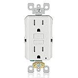
- 15 amp Non-Tamper Resistant Ground Fault Circuit Interrupter (GFCI) outlet receptacle for indoor use. Please kindly check if the depth of electrical box can fit our GFCI outlets before purchasing.
- The indicator light will turn On GREEN once the power is ON. Press the RESET button to restore power to the GFCI outlet. The LED indicator keeps GREEN no matter you press the RESET or TEST button.
- The ETL certification is a sign of a better quality product. This product has gone through many test procedures before getting its approval which makes it the safest GFCI.
- Back and side wired for easy installation. Decorator wall plate and screws included. Caution: Do not unscrew the terminal screws too far or with excessive force. Do not use power tools to loosen the terminal screws.
- 15A/125V/1875W. Wallplate Included, ETL Listed
- GFCI Outlet - Constructed with premium high-impact resistant thermoplastic materials and rational structure design, ensures superior strength and durability. it a single gang GFCI electrical box that supports a standard duplex, grounded receptacle
- Safe electrical GFCI outlet tester with TEST and RESET buttons and LED Indicator is designed to meet local and national electrical codes.
- Safty - The ANKO GFCI USB Outlet meets UL-Listed YGB-094WR, 20 Amp, 125 Volt, 60HZ. Tamper Resistant Receptacle prevents young children from inserting unwanted objects into the outlets. For an added layer of protection, the GFCI regularly conducts an automatic internal test to confirm that it can respond to a ground fault, provides continuous ground fault protection.
- Weather Resistant - Constructed with advanced UV stabilized engineering to provide superior corrosion, temperature, and UV resistance, preventing discoloration and aging, ideal for outdoor & indoor use. Ground fault circuit interrupter GFCI outlets are required in kitchens and bathrooms and within 25 feet of heating, air conditioning and refrigeration equipment to prevent electrical shock in areas subject to moisture.

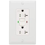
- 【20 Amp GFCI Outlet】Ground Fault Circuit Interrupter (GFCI) receptacle is designed to recognize a ground fault in your wiring and immediately breaks the flow of electricity, thus protecting you from electrical shock. Please kindly check if the depth of electrical box can fit our GFCI outlets before purchasing.
- 【Automatic Self-Test】The red LED light blinks every 30 seconds indicating a successfull self-test. If the red LED light stays ON, the test has failed and the GFCI must be immediately replaced.
- 【Weather Resistant】Weather Resistant (WR) GFI is constructed with advanced UV stabilized engineering to provide superior corrosion, temperature, and UV resistance, preventing from discoloration and aging, ideal for outdoor use.
- 【Tamper Resistant】Tamper resistant receptacle has spring-loaded shutters that close off the socket openings. An important next step to making the home safer for children.
- 【Easy to Install】Easy Installation with back or side wiring. Screwless wall plates, screws and installation instructions included. Caution: Do not unscrew the terminal screws too far or with excessive force. Do not use power tools to loosen the terminal screws. 20A/125V/2500W, UL Listed.

- 【15 Amp GFCI Outlet】Ground Fault Circuit Interrupter (GFCI) receptacle is designed to recognize a ground fault in your wiring and immediately breaks the flow of electricity, thus protecting you from electrical shock. Please kindly check if the depth of electrical box can fit our GFCI outlets before purchasing.
- 【Self-Test】The red LED light blinks indicating a successfull self-test. If the red LED light stays ON, the test has failed and the GFCI must be immediately replaced.
- 【Tamper Resistant】Tamper resistant receptacle has spring-loaded shutters that close off the socket openings. An important next step to making the home safer for children.
- 【Easy to Install】Easy Installation with back or side wiring. Screwless Wallplate and installation instructions included. Caution: Do not unscrew the terminal screws too far or with excessive force. Do not use power tools to loosen the terminal screws.
- 【Certification 】15A/125V/1875W. ETL Listed. Caution: Do not unscrew the terminal screws too far or with excessive force. Do not use power tools to loosen the terminal screws.

- 【15 Amp GFCI Outlet】Ground Fault Circuit Interrupter (GFCI) receptacle is designed to recognize a ground fault in your wiring and immediately breaks the flow of electricity, thus protecting you from electrical shock. Please kindly check if the depth of electrical box can fit our GFCI outlets before purchasing.
- 【Automatic Self-Test】The red LED light blinks every 30 seconds indicating a successfull self-test. If the red LED light stays ON, the test has failed and the GFCI must be immediately replaced.
- 【Tamper Resistant】Tamper resistant (TR) receptacle has spring-loaded shutters that close off the socket openings. An important next step to making the home safer for children.
- 【Easy to Install】Easy Installation with back or side wiring. Wall plates, screws and installation instructions included. Caution: Do not unscrew the terminal screws too far or with excessive force. Do not use power tools to loosen the terminal screws.
- 【Certification 】15A/125V/1875W. UL Listed.


- ✅【Innovative Dual Protection System】 Features twin solenoid and double Silicon Controlled Rectifier (SCR), ensuring an always-on GFCI protection to ground fault, which doubles the service life of GFCI as an added layer of protection. UL & CUL Listed.
- ✅【Patented Self-Test Every 5 Seconds】 The GFCI outlet automatically conducts self-test (auto-monitor) every 5 seconds to ensure the GFCI is continually working to protect people from electrocution, which exceeds the UL standards of self-test frequency of 3 hours. Break the circuit in just 0.025 seconds when ground fault occurrence in the circuit.
- ✅【Tamper Resistant】 Tamper-resistant shutter system prevents young children from inserting unwanted objects into the outlets.
- ✅【Durable and Long Service Life】Constructed with premium high-impact resistant thermoplastic materials and rational structure design, ensures superior strength and durability. Performed 6000+ times endurance factory test, which is twice the testing times of UL standard.
- ✅【Always Safe】 Strictly tested as per or exceeds UL943 & UL498 requirements. The surge protection and lightning protection function withstanding 6 kilovolt. Innovated Reset-Disable System ensures the GFCI cannot be reset once it reaches the “end of life”. Reversed Wiring Prevention makes it no power at the GFCI outlet and downstream if the LINE / LOAD is wired incorrectly.

- Provides continuous ground fault protection – detects and trips on actual ground fault even when self-test is being conducted
- Periodically conducts an automatic internal test to confirm that it can respond to a ground fault
- Terminals allow for easy wiring options – back and side wire capable
- 15 Amp, 125 Volt Receptacle/Outlet
Last update on 2024-06-11 / Affiliate links / Images from Amazon Product Advertising API
This product presentation was made with AAWP plugin.