
NHTSA ID Number: 10162801
Manufacturer Communication Number: TP-H633 Rev I
TSB/Document Date: 2019-07-15
Summary
Operation Name: Hendrickson Auxiliary Axle Systems Document Name: Technical Procedure - COMPOSILITE SC Steerable Auxiliary Axle Suspension Systems; Installation & Preventive Maintenance Procedure Summary: This document provides installation and preventive maintenance procedures for Hendrickson COMPOSILITE SC auxiliary axle suspension systems.
3. Install wheels and lug nuts, tighten to proper torque, refer Torque Specification section in
this publication.
4. Ensure there is lubrication in the wheel end by using the necessary inspection methods,
reference TMC Recommended Maintenance Practices Manual, Recommended for Wheel
End Lubrication Section.
5. Install the air brake lines for the steer axle brakes, per the chassis manufacturer’s
specifications.
NOTE
Suspensions purchased from Hendrickson Auxiliary Axle Systems require brake adjustment (refer
to the brake manufacturer for procedure), supplied with automatic slack adjusters.
6. Inspect the brakes and adjust if necessary.
TP–H633
17
Pre-Installation/Installation Check List
COMPOSILITE® SC Steerable Auxiliary Axle Suspension Systems
SECTION 6
Initial Axle Adjustments/Final Inspection
TOE SETTING
Toe is the relationship of the distance between the front of the tires and the distance between
the rear of the tires on the same self-steer axle measured at spindle height. When the front
distance is less than the rear distance, the wheels are in a “toe-in” condition.
The steer axles come pre-aligned, however it is the responsibility of the installer to ensure the
toe is correct prior to the vehicle entering service.
Refer to Hendrickson Literature No. TP–H785 for Toe Setting Procedure.
TURN ANGLE - MECHANICAL STOP
FIGURE 6–1
A mechanical turn angle stop bolt is an adjustable fastener that limits the axle’s turn radius
angle and allows users to avoid tire contact
with the vehicle accessories. Ensure that the
turn angle stop is set so wheel interference
does not occur.
NOTE
Factory settings of turn angle stop bolts varies.
1. Adjust the auxiliary axle turn angle stop
bolt, see Figure 6–1, to achieve maximum
turn angle while providing adequate
chassis clearance.
2. Tighten the turn angle jam nut to the
specified torque. Refer to the Torque
Specifications Section in this publication.
■■
OPTIONS
AXLE CONTROLS
When operating a truck in reverse (backing), a conventional self–steering axle must be either
raised or locked into a non-steering configuration. Refer to Hendrickson publication OM H817
LC Auxiliary Axle Control Kits.
LOCK STRAIGHT
The lock straight kit is available as an option on the Hendrickson COMPOSILITE suspension
system. This kit straightens the self-steer axle wheels and locks them in place in the down or up
position. This kit is only available on select models and must be specified at time of purchase.
MANUAL AND AUTOMATIC LIFT
An alternative method to locking the steering mechanism is to lift the suspension when reversing. Various manual and electric air control kits are available as options. Contact Hendrickson
Auxiliary Axle Customer Service for more details.
Initial Axle Adjustments/Final Inspection
18
TP–H633
COMPOSILITE® SC Steerable Auxiliary Axle Suspension Systems
FINAL INSPECTION
1. Check that all suspension bolts are tightened, refer to Torque Specifications section in this
publication.
2. Check the air control system and plumbing for leaks and proper valve function.
3. Move the suspension through its entire travel with wheels and tires installed to ensure
that adequate component clearances (i.e. air springs, brake chambers, etc.) have been
provided.
WITH THE VEHICLE UNLOADED, THE RIDE (OR DOWN) AIR SPRING AIR PRESSURE MUST BE LIMITED
TO A MAXIMUM OF 30 PSI TO AVOID IMPROPER VEHICLE LOADING OR COMPONENT DAMAGE.
4. Inspect the auxiliary axle for the following:
TP–H633
■■
Wheels lug nuts are tightened to torque
■■
Wheels rotate freely
■■
Brakes are properly adjusted
■■
Wheel hubs are sufficiently filled with the manufacturer’s recommended lubricant
19
Initial Axle Adjustments/Final Inspection
COMPOSILITE® SC Steerable Auxiliary Axle Suspension Systems
SECTION 7
Preventive Maintenance
Following appropriate inspection procedures is important to help ensure the proper maintenance
and operation of the steerable suspension and component parts. Hendrickson recommends the
COMPOSILITE suspension be inspected at pre-delivery, the first in-service inspection and regular
preventive maintenance intervals. Inspection must include the following items and other components referenced in this section.
HENDRICKSON RECOMMENDED
INSPECTION INTERVALS
FIRST IN-SERVICE
INSPECTION
PREVENTIVE MAINTENANCE
Wheel Bearings – Verify end play is between 0.001" and
0.005". Adjust and lubricate as required
8,000 Miles or every 3 months,
whichever comes first
Tie Rod Ends – Inspect for leaking and lubricate as required
10,000 Miles or every 6 month,
whichever comes first
Kingpin Bushings – Check for wear and grease as required
Within the first
3,000 Miles
Pivot Connections – Verify Torque
5,000 Miles or as needed
Stabilizers – Check for leaking and adequate return
Brake Assembly Components – Inspect for leaking and
component wear
10,000 Miles or every 6 months,
whichever comes first
3,000 Miles
20,000 Miles or every 10 months,
whichever comes first
COMPONENT INSPECTION
■■
■■
■■
■■
■■
■■
Air Spring — Look for chaffing or any signs of spring or component damage
Fasteners — Look for any loose or damaged fasteners on the entire axle assembly. Ensure
all fasteners are tightened to the specified torque. Use a calibrated torque wrench to check
torque in a tightening direction. As soon as the fastener starts to move, record the torque.
Correct the torque if necessary. Replace any worn or damaged fasteners.
Operation — All steering components must move freely through the full range of motion
from axle stop to axle stop
Steering pivot points — Check for looseness at all pivot points. Inspect and lubricate all
pivot points
Tire wear — Inspect tires for wear patterns that may indicate suspension damage or misalignment. See Tire Inspection in this section
Wear and damage — Inspect all parts of axle for wear and damage. Look for bent or
cracked parts. Replace all worn or damaged parts
See vehicle manufacturer’s applicable publications for other preventive maintenance requirements.
NOTE
Preventive Maintenance
Non–functioning components are to be returned to Hendrickson Specialty Products - Auxiliary
Axle Systems, in exchange for replacement components, provided product warranty conditions
are met.
20
TP–H633
COMPOSILITE® SC Steerable Auxiliary Axle Suspension Systems
LUBRICATION INTERVALS
Regular lubrication intervals should be followed to help prevent premature wear to the kingpin
bushings and tie rod ends.
GREASING AND LUBRICATION SPECIFICATIONS
COMPONENT
GREASING INTERVAL
Kingpin Break In
5,000 miles or as needed
Kingpin Bushing
Taper Tie Rod End
GREASE
10,000 miles or every 6 months
NLGI–1 or NLGI–2
KINGPIN LUBRICATION
On the Hendrickson COMPOSILITE, the kingpin grease fittings are located on the top and bottom
of the kingpin grease caps.
1. Prior to greasing the kingpins, the axle must be on the ground in a loaded condition.
2. Clean off all the grease fittings with a clean shop towel prior to lubrication.
FIGURE 7–1
3. Lubricate the kingpins through the
grease fittings on the top and bottom
of the steering knuckle.
4. Force the required lubricant into the
upper and lower kingpin grease fittings until new lubricant flows from
locations A and B, see Figure 7–1.
NOTE
Greasing at the lower zerk should purge
grease from the thrust bearing shell.
TIE ROD END LUBRICATION
LUBRICATION PROCEDURE
1. Wipe the grease zerk and grease gun tip with clean shop towels.
2. Wipe the seal/boot clean with shop towels.
3. Attach a grease gun to the grease zerk. Either a hand or pneumatic grease gun is acceptable. If air operated grease gun is used, system air pressure should not exceed 150 psi
(1035 kPa).
FIGURE 7–2
EXCEEDING THE MAXIMUM AIR PRESSURE TO
THE GREASE ZERKS CAN CAUSE DAMAGE TO THE
DUST BOOT AND COMPONENT FAILURE.
4. Dirt, water, and discolored old grease
should flow from the relief vents or purge
holes near the boot crimp or bellows area,
see Figure 7–2. Continue to purge grease
until fresh grease flows from the purge
area.
Dust Boot
Boot Crimp
Zerk Fitting
TP–H633
21
Preventive Maintenance
COMPOSILITE® SC Steerable Auxiliary Axle Suspension Systems
5. If the tie rod end is designed for lube service and it will not accept grease proceed as follows:
a. Remove the grease zerk.
b. Inspect the threaded grease zerk hole in the tie rod end and remove any obstructions.
c. Install a new grease zerk.
d. Continue the lubrication procedure.
e. If the tie rod end will not accept grease following this procedure it will be necessary to
replace the tie rod end, see Tie Rod End replacement in the Component Replacement
Section of this publication.
6. Apply grease until all the old grease is purged from the boot.
LIFT AXLE (LA) AND COMPLIANT TIE ROD (CTR) STRUCTURAL
INSPECTION
Periodic inspection of the LA and CTR are strongly recommended. Cleaning the LA and CTR prior
to the inspection will improve the ability to see all structural component condition.
TIE ROD ADJUSTMENT/TOE SETTING ADJUSTMENT
For additional information regarding toe settings or lift axle systems, please contact the
Hendrickson Customer Service Department at 800–660–2829.
Refer to Hendrickson Literature No. TP–H785 to adjust the toe setting procedure.
TIE ROD END INSPECTION
■■
STANDARD TAPER TIE ROD
INSPECTION PROCEDURE
Before beginning this inspection procedure, the entire system must be unloaded.
DO NOT GREASE THE TIE ROD ASSEMBLY BEFORE PERFORMING THE INSPECTION. DOING SO CAN
INHIBIT EFFORTS TO DETERMINE ACTUAL WEAR.
REPLACE THE ENTIRE TIE ROD END IF THE BOOT IS TORN OR MISSING, FAILURE TO DO SO CAN CAUSE
PREMATURE WEAR OF THE TIE ROD END.
1. Chock the rear wheels of vehicle.
2. Set the parking brake.
3. Raise the lift axle and support with jack stands.
4. Check that the boots are in place and completely installed over the tie rod ends.
5. Check for cracking or tears in the boots. Also check the boot seals for damage. Replace the
entire tie rod end if the boot is damaged.
THE CORRECT COTTER PIN MUST BE INSTALLED THROUGH THE TIE ROD END WITH THE CASTLE NUT
TIGHTENED TO THE PROPER TORQUE SPECIFICATION IN ORDER TO SECURELY ATTACH THE TIE ROD. A
MISSING COTTER PIN CAN CAUSE THE TIE ROD END NUT TO BECOME LOOSE AND CAUSE ADVERSE
AUXILIARY AXLE PERFORMANCE.
6. Check that the tie rod end nut is installed and secured with a cotter pin. If the cotter pin is
missing, check the nut torque specification and then install a new cotter pin. Always tighten
the castle nut to specified torque when setting the cotter pin. DO NOT back off the nut to
insert cotter pin.
Preventive Maintenance
22
TP–H633
COMPOSILITE® SC Steerable Auxiliary Axle Suspension Systems
IT IS CRITICAL TO CHECK THE 5⁄8" TIE ROD CLAMP BOLT HEAD LOCATION TO VERIFY THE CLAMP
FASTENERS HAVE SUFFICIENT CLEARANCE AWAY FROM THE LOWER STABILIZER MOUNT AT FULL
WHEEL CUT. THE FASTENERS MUST NOT CONTACT THE LOWER STABILIZER MOUNT. FAILURE TO DO
SO CAN CAUSE ONE OR MORE COMPONENTS TO FAIL CAUSING ADVERSE VEHICLE HANDLING AND
POSSIBLE PERSONAL INJURY OR PROPERTY DAMAGE.
7. Verify the 5⁄8" tie rod clamp bolt head does not contact the lower shock mount at full wheel
cut, see Figure 7–3.
THE THREADED PORTION OF THE TIE ROD END MUST EXTEND PAST THE SLOTS INTO THE TIE ROD
CROSS TUBE, SEE FIGURE 7–3. FAILURE TO DO SO CAN CAUSE COMPONENT DAMAGE, ADVERSE
VEHICLE HANDLING AND POSSIBLE PERSONAL INJURY OR PROPERTY DAMAGE.
8. Check that the tie rod end is threaded correctly into the tie rod cross tube and is engaged
deeper than the end of the tie rod cross tube slot. The tie rod end must be visible the entire
length of the tie rod cross tube slot, see Figure 7–3.
9. Check that grease zerks are installed. Replace a damaged grease zerk with a new one.
FIGURE 7–3
5/8" Tie
Rod Clamp Bolt
It is critical to check the 5/8" tie rod clamp
bolt head location to verify the clamp
fasteners have sufficient clearance away
from the lower shock mount at full wheel
cut. The fasteners must not contact the
lower shock mount.
Tie Rod Cross Tube Slots
It is critical to have the threaded
portion of the tie rod end extend past
the slots in the tie rod cross tube.
Threaded Portion
of the Tie Rod End
5/8" Tie
Rod Clamp Locknut
Tighening Torque 45-50 ft. lbs.
DO NOT USE THE FOLLOWING ITEMS OR METHODS TO CHECK FOR MOVEMENT OF THE TIE ROD
ASSEMBLY WHICH CAN CAUSE DAMAGE TO COMPONENTS:
■■
■■
■■
A CROW BAR, PICKLE FORK, OR 2 x 4
ANYTHING OTHER THAN HANDS USED TO GRASP AND ROTATE THE TIE ROD CROSS TUBE
ASSEMBLY (CAN RESULT IN DAMAGE TO THE TIE ROD CROSS TUBE)
EXCESSIVE PRESSURE OR FORCE APPLIED TO THE TIE ROD ENDS OR THE JOINTS OF THE
ASSEMBLY
10. By hand rotate the tie rod cross tube toward the front of the vehicle and then toward the
rear. After rotating, center the tie rod cross tube. If the tie rod cross tube will not rotate in
either direction, replace both tie rod ends, see Figure 7–4.
FIGURE 7–4
TP–H633
23
Preventive Maintenance
COMPOSILITE® SC Steerable Auxiliary Axle Suspension Systems
FIGURE 7–5
11. Position yourself directly below the tie rod
end. Using both hands, grab the assembly end as close to the tie rod end as
possible (no more than 6" or 152.4 mm).
Apply hand pressure with reasonable
human effort vertically up and down in
a push-pull motion several times (using
approximately 50–100 pounds of force).
Check for any movement or looseness
at both tie rod end locations (See Figure
7–5).
To check for looseness
push up and down
on tie rod to check
for movement
FIGURE 7–6
12. If there is any movement in the tie rod
assembly, install a magnetic based dial
indicator on the Ackermann arm (See
Figure 7–6).
13. Set the dial indicator to zero.
14. Apply hand pressure with reasonable
human effort vertically up and down in
a push-pull motion several times (using
approximately 50-100 pounds of force).
Observe the reading on the dial indicator.
15. If the reading is more than 0.060",
replace both tie rod ends at the next service interval.
16. If a tie rod end exhibits 0.125" of movement by hand, the vehicle should be
removed immediately from use and the
tie rod end be replaced.
17. Remove jack stands and lower the lift axle.
18. Remove wheel chocks.
■■
HEAVY–DUTY COMPLIANT TIE ROD (HD CTR)
INSPECTION PROCEDURE
FIGURE 7–7
1. Chock the rear wheels of vehicle.
2. Set the parking brake.
3. Raise the lift axle and support with jack
stands.
4. Inspect rubber bushing for wear or damage (See Figure 7–7).
5. Inspect all metal components for a bent
or cracked condition (See Figure 7–7).
6. Inspect and verify torques values for all
fasteners. Refer to Torque Specification
Section of this publication for torque
requirements.
Preventive Maintenance
24
TP–H633
COMPOSILITE® SC Steerable Auxiliary Axle Suspension Systems
NOTE
Contact Hendrickson Auxiliary Axle Customer Service with any questions or concerns.
7. Remove jack stands and lower the lift axle.
8. Remove wheel chocks.
KINGPIN BUSHING INSPECTION
INSPECTION PROCEDURE
1. Chock the rear wheels to help prevent the vehicle from moving.
2. Set the parking brake.
3. Raise the lift axle and support with jack stands.
4. CHECKING THE UPPER KINGPIN BUSHING.
a. Affix a magnetic base dial indicator on the axle and place the tip of the dial indicator
on the inside of the upper kingpin connection as shown in Figure 7–8.
b. Set the dial indicator to “0” zero.
c. Move the top of the tire in and out by applying reasonable, constant pressure and then
releasing.
d. Check the reading on the dial indicator. If the dial indicator moves more than 0.025",
the upper bushing is worn or damaged. Replace both bushings. Refer to the Kingpin
Bushing Removal and Installation sections in this publication.
5. CHECKING THE LOWER KINGPIN BUSHING
a. Install a dial indicator so that the base is on the axle and the indicator tip is against the
inside of the bottom of the knuckle.
b. Set the dial indicator to “0” zero.
IMPORTANT
If one bushing is worn or damaged, it is mandatory to replace both the top and bottom bushings
on that knuckle assembly.
FIGURE 7–8
FIGURE 7–9
6. Remove jack stands and lower the lift axle.
7. Remove wheel chocks.
STEERING KNUCKLE INSPECTION AND ADJUSTMENT
CHECKING VERTICAL END PLAY (UP AND DOWN MOVEMENT)
1. Chock the rear wheels of the vehicle.
2. Set the parking brake.
3. Raise the lift axle and support with jack stands.
TP–H633
25
Preventive Maintenance
COMPOSILITE® SC Steerable Auxiliary Axle Suspension Systems
4. If necessary, remove the wheels, hubs and drums.
5. Place a dial indicator on each side of the axle as follows:
a. Ensure wheels are positioned straight ahead.
b. Place the magnetic dial indicator base on the axle.
c. Place the tip of the dial indicator on top of the upper kingpin connection.
6. Place a jack and a wood block (with a hole that allows clearance for the lower kingpin
grease fitting) under the lower kingpin grease cap area (See Figure 7–9).
7. Set the dial indicator to “0” zero.
8. Raise the jack until the dial indicator shows the end of vertical travel. Measure and record
the dial indicator reading. Vertical (up and down) inspection clearance must be between
0.008" and 0.030".
ADJUSTING VERTICAL END PLAY
1. If vertical clearance is greater than 0.030", replace the thrust bearing.
2. After replacing the thrust bearing, if vertical clearance is greater than 0.018", install shims
(Hendrickson Part No. R-001764-1Q12) between the top of the axle and the bottom of the
upper kingpin connection to obtain the proper clearance specification. See the Steering
Knuckle Disassembly section.
3. If vertical clearance is less than 0.008", remove the shims from between the top of the
axle and the bottom of the upper kingpin connection to obtain the proper clearance
specification.
4. Repeat Steps 2 or 3 until proper clearance is achieved.
5. Remove jack stands and lower the lift axle.
6. Remove wheel chocks.
STABILIZER
INSPECTION
Inspection of the stabilizer can be performed by conducting a visual inspection for leaking
or damage.
1. Lower the axle to the ground
2. Chock the rear wheels to help prevent the vehicle from moving.
3. Set the parking brake.
NOTE
It is important to inspect the stabilizer fully extended.
4. Evidence of the following potential problems indicates replacement of your stabilizer is
necessary:
Damaged inner or outer mounts
Damaged inner or outer bushings
■■
Damaged dust cover
■■
Bent or dented stabilizer
■■
Evidence of improper installation. For instance, washers installed incorrectly.
■■
Fluid leaking in streams from the upper seal
5. Remove wheel chocks.
■■
■■
ALTERNATE INSPECTION PROCEDURE
1. Remove the stabilizer.
Preventive Maintenance
26
TP–H633
COMPOSILITE® SC Steerable Auxiliary Axle Suspension Systems
2. Once removed, shake the suspected stabilizer and listen for the sound of metal parts rattling inside. Rattling of internal parts can indicate a failure.
FIGURE 7–10
STABILIZER VISUAL INSPECTION - UNACCEPTABLE CONDITIONS
3. Replace as needed.
4. Remove jack stands and lower the lift axle.
5. Remove wheel chocks.
STABILIZER ANGLE INSPECTION
Hendrickson recommends verifying the stabilizer angle to ensure it is within the recommended
3 to 5 degree angle (See Figure 7–11).This can be done by use of a digital protractor or equivalent device. If the angle of your stabilizer does not meet the 3–5 degrees, contact Hendrickson
Customer Service for the necessary spacers. After necessary spacers are added repeat procedure to verify angle is within specifications.
FIGURE 7–11
TIRE INSPECTION
The leading potential causes of tire wear on commercial vehicles according to TMC (The
Technology & Maintenance Council) are the following in order of importance:
1. Tire Pressure
2. Toe Setting
3. Thrust Angle
4. Camber
The following tire Inspection guidelines are based upon TMC recommended practices. Any
issues regarding irregular tire wear where Hendrickson is asked for assistance, will require tire
and alignment maintenance records as described in the TMC Literature No. RP 642 (Guidelines
for Total Vehicle Alignment).
TP–H633
27
Preventive Maintenance
COMPOSILITE® SC Steerable Auxiliary Axle Suspension Systems
Tire wear is normally the best indicator of vehicle alignment condition. If tires are wearing too
rapidly or irregularly, alignment corrections may be needed. The tire wear patterns described
below can help isolate specific alignment problems.
The most common conditions of concern are:
■■

- 💯【Conta.ct us for Support Directly】If you met any...
- 🔥🔥🔥【2026 AUTEL FLAGSHIP MK900BT MK900-BT, NEW...
- 🚗【3000+ ACTIVE TESTS (50➡3000+), SAME AS MS...
- 🚗【40+ HOT SERVICES FOR 150 MAKES (28+➡40+)】Full...
- 🚗【OE ALL SYSTEM DIAGNOSE, AUTO SCAN 2.0: SCAN LICENSE...

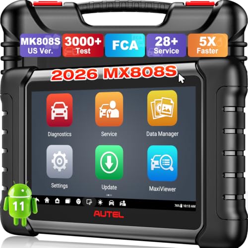
- 📌【We are Here for You】Dear valued customer, please be...
- 🚀【5X Faster Next-Level Hardware, Same as MK900/ MX...
- 🔥【3000+ Active Tests = MK900/MK900BT but...
- 📢【2026 U.S. Version, All-in-One as MK808S/ MK808Z...
- 🔥【28+ Hot Services for 150+ Brands】Same as MaxiCOM...
If the PDF is very large, it may not load in the preview below.
Some older TSBs had multiple PDFs — visit the NHTSA Website to view all PDFs.
If the TSB PDF does not show, download or view it on the NHTSA Website.
Click on the (+) Plus Sign
Then Click on Associated Document(s)
Search NHTSA Database for Recalls
Search NHTSA Database for Vehicle Investigations
View Latest Vehicle Investigations
Search NHTSA Database for Vehicle Complaints
View Latest Vehicle Complaints
TSB/Document ID: TP-H633 Rev I
Replacement Service Bulletin Number:
MFR Communication Date: 2019-03-01
MFR Internal Campaign ID/Software Version:
Communication Type: Service Bulletin/Repair Instructions
NHTSA Components: ELECTRONIC STABILITY CONTROL:AUTOMATIC (ASC)
MFR Component System:
MFR Component Subsystem:
Previous TSB | Next TSB |

- [Notice] When you receive a used device, it may be a customer return resold by Amazon without inspection. You can exchange it for a new one through Amazon. As this situation is unavoidable, we sincerely apologize. For any issues, contacting us via Amazon's "Messages" is the best way. THINKSCAN 689BT Bidirectional Scan Tool Can Be Used Immediately After It is Turned On, Without Complicated Registration Process, Which is More Convenient & Quick.
- Full Bi-Directional Control & 3000+ Active Tests: Take control and test components like actuators, fuel injectors, relays, and cooling fans in real time. You’ll quickly see if the problem is in the part itself or the control module — saving you hours of guesswork and frustrating trial-and-error.
- Advanced ECU Coding Capabilities: Handle module matching and hidden feature activation with confidence. When you replace an ECU or want to customize settings, this obd2 scanner diagnostic bi directional tool gives you the professional-level capabilities you need without the dealership price tag.
- 34+ Useful Reset and Maintenance Functions: Complete everyday service tasks smoothly with a wide range of helpful reset and maintenance functions. Whether you’re keeping up with regular upkeep or tackling a specific job, this scanner makes maintenance simpler and less stressful for both DIYers and pros.
- Comprehensive Full System Diagnostics: Diagnose every major system — Engine, Transmission
 , ABS, SRS, TPMS, and more — all in one place. Finally stop wondering if you’re missing something important; get the full picture and clear codes with ease.

- Top Reasons to Choose the D7S OBD2 Scanner: XTOOL D7S car scan tool, an upgrade of XTOOL D7, offers comprehensive features for automotive technicians, workshops, and DIY enthusiasts 1. Upgraded Hardware: 2+64GB memory, rear camera, intuitive interface, foldable bracket 2. Complete Diagnostics: FCA Autoauth, OE-level all system scan, 39+ maintenance services, 4K+ bidirectional, CANFD/DoIP protocol 3. Advanced Capabilities: ECU coding, PMI functions 4. Wide Compatibility: Support 10,000+ models, covering 99% vehicle brands 5. Multi-language: Available in 22+ languages, No IP Restrictions 6. 3-Year Updates: Save 300 bucks on software updates for the latest features and optimizations
- 2026 Upgraded D7S Car Scanner Features: The newly 2026 D7S V2.0 scanner for car brings exciting features for advanced vehicle diagnostics and enhanced user experience 1. FCA AutoAuth: Now supports FCA SGW module for Chrysler, for Jeep, for Dodge (2018+), for Fiat (2017+), enabling faster vehicle communication without gateway restrictions 2. PMI (Offline ECU Programming): Allows for Ford, for Lincoln, and for Mazda ECU programming for new modules 3. Optimized Diagnostic Report 2.0: Personalized reports with logos and customer info for auto shops. Note: Compatibility varies by cars, please check before order
- Cost-effective ECU Coding Scan Tool for Specific Brands: Enhance your vehicle's performance with XTOOL D7S! This obd2 scanner all systems bidirectional offers advanced capabilities at an affordable price, supports online for BMW, for Benz and offline for BENZ, for MIT, along with PMI functions for Ford, for Mazda, and for Lincoln. Ideal for technicians and DIY enthusiasts, this automotive scanner diagnostic tool optimizes vehicle performance and enhances the driving experience. Note: Not for all cars and modules, please send car VIN to check the compatibility before purchase
- OE All System Diagnostic & 8 Pids Graphing: XTOOL D7S is a comprehensive all system bi directional obd2 scanner that delivers dealer-level diagnostics, completely controlling over your vehicle’s performance and health. This automotive scan tool can read and clear DTCs, view live data and ECU information, retrieve freeze frames, and perform active tests and full obd2 functions. This bi-directional scan tool can can identify your vehicle's make, model, and year information with just one click and show up to 8 PIDs live data with options for CSV viewing, playback, and recording for in-depth analysis. It is easy-to-use for both professionals and beginners, helping pinpoint issues efficiently
- 3 Years Software Update, Value for Money: With 3 years of software updates and 22+ languages(no IP restrictions), XTOOL D7S auto scanner code scanner ensures ongoing compatibility for the latest car models and improved diagnostic functions. This all system vehicle diagnostic scanner comes with a 30-day return policy and a 24-month repair for dependable performance. XTOOL are dedicated to your satisfaction, so enjoy seamless support and lifetime expert assistance. Should you encounter any issues or concerns, don’t hesitate to reach out XTOOL. D7S with newest update with 22 languages freely transfer without authorization, check details from setting-language or from XTOOL

- 【✅Compared to BOSSCOMM IF742, IF745 Offers Full-System Diagnostics】The BOSSCOMM IF745 car diagnostic scanner is an upgraded model of IF742. In addition to supporting all OBD2 Code Reader functions and 6 reset options (ABS/EPB/SAS/BMS/Oil/Throttle), it expands diagnostics from 4 systems (Check Engine/ABS/SRS/Transmission) to vehicle All systems, including Steering, Suspension, and Body Electronics. This provides deeper, more comprehensive diagnostic capabilities.
- 【✨6 Essential Resets: ABS Bleeding, Oil, EPB, SAS, Throttle, BMS】The BOSSCOMM IF745 obd2 scanner diagnostic tool swiftly purges air from brake lines to restore braking sensitivity, fine-tunes maintenance cycles to eliminate false alerts, resolves parking brake issues with one-click control, recalibrates steering sensors for stability, optimizes engine idling/acceleration for smoother performance, and deeply resets battery systems to extend lifespan and range via precise parameter adjustments.❗NOTE: Does NOT support bidirectional control, coding, or programming.
- 【✨Deep Diagnostics for All Vehicle System Modules】Beyond code reading/clearing and ECU information retrieval, our all-in-one data stream feature lets you inspect all current fault codes and their locations across the vehicle’s systems. This vehicle code reader helps you turn off dashboard warning lights and perform a comprehensive self-check of your car at home—no more back-and-forth trips to the repair shop or hefty inspection fees.
- 【✨10 OBD2 Functions】The BOSSCOMM IF745 scan tool’s DTC Lookup instantly translates fault codes into user-friendly explanations, its I/M Readiness feature streamlines emissions testing with a single tap, and Freeze Frame lets you pinpoint the exact moment of a fault for in-depth root-cause diagnosis. Combined with a live data dashboard and advanced diagnostics (O2S, OBMon, EVAP), it delivers comprehensive insights for confident troubleshooting.
- 【✨10,000+ Car Models, AutoVIN, 13 Languages】The BOSSCOMM IF745 vehicle scanner diagnostic tool covers 73+ global car brands and offers support in 13 languages, making it perfect for DIYers, auto mechanics, or as a thoughtful gift. With a single-click AutoVIN feature, it instantly retrieves vehicle serial numbers, streamlining diagnostics for users globally. This adaptable tool balances user-friendliness with precision, catering to both personal and professional requirements.✅Unsure about compatibility? Compatibility will vary on vehicles' model and year, pls reach us via 📧 [email protected] 📧 before purchase.
This product presentation was made with AAWP plugin.