
NHTSA ID Number: 10162801
Manufacturer Communication Number: TP-H633 Rev I
TSB/Document Date: 2019-07-15
Summary
Operation Name: Hendrickson Auxiliary Axle Systems Document Name: Technical Procedure - COMPOSILITE SC Steerable Auxiliary Axle Suspension Systems; Installation & Preventive Maintenance Procedure Summary: This document provides installation and preventive maintenance procedures for Hendrickson COMPOSILITE SC auxiliary axle suspension systems.
Important Safety Notice
COMPOSILITE® SC Steerable Auxiliary Axle Suspension Systems
SECTION 4
Special Tools
The following tools / materials are needed when installing and servicing Hendrickson
COMPOSILITE SC steerable systems:
Bushing Inspection
■■
■■
Two jack stands
Small bottle jack
■■
■■
Block of wood
Magnetic base dial indicator
Steering Knuckle Disassembly
■■
■■
■■
½" Impact
Wrench or socket – 7⁄16" and 15⁄16"
15⁄16" Box wrench
■■
■■
■■
Deep well socket – 15⁄16" and 11⁄8"
Brake spring tool or notched screw driver
Needle nose pliers
Kingpin Inspection and Replacement
■■
■■
■■
Cleaning solvent and emery cloth (220 grit
or higher)
1"-2" Micrometer measuring device
11⁄16" Socket and impact gun
■■
■■
■■
3⁄8"
Punch
Hammer
Portable hydraulic (5-10 ton) press
Bushing Housing Replacement
■■
Hydraulic shop press with a minimum force
capacity of 5 tons
■■
■■
Bushing driver
Magnetic base dial indicator
Steering Knuckle Assembly
■■
■■
■■
■■
15⁄16"
Box wrench and deep well socket
Brake spring tool or notched screw driver
Wrench or socket – 7⁄16", 15⁄16"
Two 0.010" feeler gauges
■■
■■
■■
Magnetic base dial indicator
Needle nose pliers
Torque wrench capable of 500 foot pounds
Kingpin Lubrication
■■
Multipurpose NLGI-2 grease
■■
Integrated Brake Replacement
■■
Brake spring tool or notched screw driver
Steering Stabilizer Inspection and Replacement
■■
■■
11⁄8" Wrench and socket
Torque wrench
■■
Digital protractor or equivalent device
Steer Ahead and Toe Setting
■■
■■
■■
■■
15⁄16"
Wrench and socket
½" Impact
Can of white spray paint
Torque wrench capable of 60 foot pounds
and 500 foot pounds
■■
■■
Straight blade screwdriver for scribing line
in tire Linear measuring instrument (tape
measure or scales)
Jack stand
Lubrication
■■
Hand or pneumatic grease gun
■■
NLGI–1 or NLGI–2 grease
Miscellaneous
■■
Special Tools
10
TP–H633
COMPOSILITE® SC Steerable Auxiliary Axle Suspension Systems
SECTION 5
Pre-Installation/Installation Check List
Prior to any installation or maintenance, service or repair, all safety related information should
be read carefully to help prevent personal injury and to assure that proper methods are used.
Improper servicing may damage the vehicle, cause personal injury, render it unsafe in operation,
or void manufacturer’s warranty.
NOTE
Every suspension parts box shipped contains your particular suspension assembly drawing supplied by Hendrickson.
BEFORE BEGINNING THE INSTALLATION:
1. Verify that the suspension model configuration (axle drop, suspension and axle seat type)
is compatible with the vehicle’s loaded frame-to-ground measurement, intended tire size
and driveline clearance.
■■
■■
Driveline clearances should be considered when deciding the correct axle drop. In
lifted position there should be more than 2" clearance between driveline and axle
Driveline drop clearance measurement, see Figure 5–1, Dimensions A + B with axle
in full up position, Dimension C is the Spindle Centerline to Axle
FIGURE 5–1
A
Collapsed
Air Spring
B
C
2. On a truck or trailer auxiliary axle suspension application:
a. Verify that the axle spacing conforms to Federal and local bridge laws.
b. Verify that the auxiliary axle suspension location is based on:
■■
Front axle steer angle
■■
Vehicle wheel–base
■■
Maximum recommended auxiliary axle spacing
c. Verify that the vehicle will have the proper load distribution after installation.
d. Verify that there is sufficient fore/aft frame rail clearance to mount the auxiliary axle
suspension(s).
3. On truck frames:
a. Verify that the frame width is within the allowable mounting range of the auxiliary axle
suspension (refer to the suspension assembly drawing provided in your parts box).
b. Mark the location of the suspension side rails on the frame rails (refer to the suspension assembly drawing provided in you parts box). Check for interferences with any
existing brackets or mounting bolts.
c. Verify that the vehicle cross members and backing plates are correctly positioned for
proper support of the auxiliary axle suspension.
TP–H633
11
Special Tools
COMPOSILITE® SC Steerable Auxiliary Axle Suspension Systems
ADEQUATE SUSPENSION SUPPORT MUST BE PROVIDED WITHIN THE VEHICLE FRAME. A CROSS
MEMBER MUST BE LOCATED 12" FORE OR AFT OF THE SIDE RAIL PIVOT BOLT CENTERLINE. FAILURE
TO PROVIDE ADEQUATE SUSPENSION SUPPORT COULD RESULT IN SUSPENSION DAMAGE AND/OR
DAMAGE TO THE VEHICLE FRAME, SEE FIGURE 5–1.
4. Verify that the components listed in your particular suspension assembly drawing (supplied
by Hendrickson in your parts box) provide the components listed and in accurate quantities.
Contact the Hendrickson Auxiliary Axle Customer Service Department if any components
are missing or damaged.
ADJUSTABLE RIDE HEIGHT (if required)
The adjustable ride height feature accommodates five different ride heights.
The following ride height adjustment spacers are provided for the bushing saddle and the upper
air spring plate to adjust to a higher ride height.
■■
Two (2) one–inch and two (2) two–inch bushing saddle spacers
■■
Two (2) one–inch two (2) two–inch upper air spring plate spacers
TABLE 5–1
Example shown in Table 5–1 uses a suspension kit specified with a 12.5" ride
height and lists the spacers required to
meet different measured vehicle ride
heights (see Table 5–1).
NOTE
Measured Vehicle
Ride Height
Spacer Requirements
11.5"
None
12.5"
None
13.5"
1" spacer (optional)
14.5"
1" spacer required,
2" spacers (optional)
15.5"
2" spacers
Ride height is always ± 1".
RIDE HEIGHT SPACER (if equipped)
INSTALLATION
1. Determine if a spacer is needed based on the measured vehicle ride height and the nominal suspension kit ride height.
2. If no spacers are required, move to the Adjustable Frame Width in this section. If spacers
are required, move to Step 3.
3. Position the ride height spacers to accommodate required ride height, see Figures 5–2 and
5–3. The same spacer size must be used for both the bushing saddle spacer and upper air
spring plate spacer.
NOTE
DO NOT drill holes in the frame rail until the ride height is determine to be optimal. DO NOT weld
spacer in position and do not remove after installation.
FIGURE 5–2
FIGURE 5–3
Bushing
Saddle
Spacer
Upper Air Spring Spacer
Pre-Installation/Installation Check List
12
TP–H633
COMPOSILITE® SC Steerable Auxiliary Axle Suspension Systems
ADJUSTABLE FRAME WIDTH
The adjustable frame width feature allows the same suspension to accommodate frame width
ranging from 33.5 inches to 34.5 inches. The suspension will ship at 34.0 inches with one
frame width spacer in position on each side. The parts box will include two additional frame
width spacers.
ADJUSTMENT PROCEDURES
1. For the following procedures, refer to your particular suspension assembly drawing supplied
by Hendrickson in your parts box.
2. Determine the vehicle’s frame width.
■■
34.0 inch vehicle frame width — DO NOT adjust the suspension frame width.
FIGURE 5–4
■■
33.5 inch vehicle frame width:
a. L o o s e n b u t D O N O T
remove the four pivot bolts
connecting the hanger to
the bushing saddle.
b. Loosen the four bolts connecting the cross member
to the hangers.
c. Remove the frame width
spacer on both sides of the
suspension.
d. Re-torque the pivot bolts
and cross member bolts. Refer to the Torque Specifications section in this publication.
e. Reference Figure 5–4 for vehicle frame width spacer.
■■
34.5 inch vehicle frame width:
a. Loosen but DO NOT remove the four pivot bolts connecting the hanger to the bushing
saddle.
b. Loosen the four bolts connecting the cross member to the hangers.
c. Add one frame width spacer to both sides of the suspension.
d. Re-torque the pivot bolts and cross member bolts. Refer to the Torque Specifications
section in this publication.
e. See Figure 5–4 for vehicle frame width spacer reference.
SUSPENSION MOUNTING INSTALLATION
PRIOR TO INSTALLING A SUSPENSION:
1. Position the vehicle on a flat level surface.
2. Chock the wheels.
3. Determine the location of the auxiliary axle mounting position on the outside of the vehicle
frame rails. Refer to your particular suspension assembly drawing supplied by Hendrickson
in your parts box and mark the position on the front edge of the auxiliary suspension side
rails on the vehicle frame, see Figure 5–5.
4. Correct any interference that may occur between the auxiliary suspension mounting surface and any existing frame bolts or brackets (in the marked areas in Step 3). The auxiliary
suspension side rail(s) can be drilled to accommodate existing bolts.
TP–H633
13
Pre-Installation/Installation Check List
COMPOSILITE® SC Steerable Auxiliary Axle Suspension Systems
FIGURE 5–5
P3
P2
C1
P1
Auxiliary Axle Suspension
FRONT
Existing Suspension
C1 = Axle location
P1, P2, P3 = Dimensions located on Hendrickson suspension assembly drawing provided
in your parts box.
FIGURE 5–6
5. Before any modifica tions to the hanger
are made, contact
Hendrickson Engineering
at (800) 660–2843. Refer
to the suspension assembly drawing to verify that
vehicle cross members
and backing plates are
positioned correctly for
the intended axle location
(See Figure 5–6).
9" C-Channel Cross Member
Two (2) Required,
Customer Supplied
8.5" x 12" x 0.25" Thick Plate
Two (2) Required,
Customer Supplied
SUSPENSION FRAME RAIL
INSTALLATION
FIGURE 5–7
1. With the cross members and
backing plates installed in the
intended suspension location,
raise the auxiliary suspension
into position. Use both the
cross members and the previously marked suspension side
rail marks as locators.
2. Once the suspension is positioned, use C-clamps to hold
the suspension side rail and
saddle on the truck frame rail.
NOTE
C-Channel Cross Members
and Backing Plate are
Customer Supplied
Auxilairy Axle
Suspension
Saddle
Vehicle Frame Rail
Suspension
Side Rail
Mount Flush
Against Vehicle
Frame Rail.
EXCEPTION: OEM
with hole pattern is
not mounted flush.
The entire auxiliary suspension
mounting surfaces must be flush
with both the side and bottom of
the vehicle frame rails or spacers.
Failure to do so will void applicable
warranties, see Figure 5–7.
Pre-Installation/Installation Check List
14
TP–H633
COMPOSILITE® SC Steerable Auxiliary Axle Suspension Systems
3. The auxiliary suspension must remain aligned (parallel) to the other properly aligned axles
on the vehicle during the entire installation process. Verify the alignment of the suspension
using a trammel bar or measuring tape.
NOTE
Due to the steering of the axle, measuring to the wheel centers is not recommended. For a
proper alignment measure to the front edge of the suspension side rail.
4. Verify the measurements between the suspension hanger brackets at the frame and at the
bottom of the brackets are within the allowable tolerance (± 0.5") see Figure 5–8. Hangers
must be parallel to one another vertically.
A CROSS MEMBER MUST BE WITHIN 12 INCHES (MINIMUM), FORE OR AFT OF THE FRAME
BRACKET PIVOT BOLT CENTERLINE. FAILURE TO PROPERLY AND SUFFICIENTLY ATTACH THE FRAME
BOLT CONNECTIONS TO SUPPORT THE SUSPENSION OR REINFORCE THE VEHICLE FRAME CAN
RESULT IN PREMATURE FRAME FAILURE, ADVERSE VEHICLE HANDLING AND WILL VOID APPLICABLE
WARRANTIES.
FIGURE 5–8
5. Minimum recommended bolt
hole pattern for hanger to
frame attachment. Refer to
Figure 5–9 for mounting bolt
hole pattern for 8K, 10K, 13K
and 20K applications.
6. Use a 5⁄ 8"-11 UNC Grade 8
Hex Bolt for frame mounting. Tighten to required
torque, refer to the Torque
Specifications section in this
publication.
NOTE
Hanger
to Hanger
at the frame
Hanger to Hanger
at bottom of brakcet
Contact Hendrickson Auxiliary Axle Customer Service with your specific bolt pattern for evaluation of applicability.
FIGURE 5–9
TP–H633
15
Pre-Installation/Installation Check List
COMPOSILITE® SC Steerable Auxiliary Axle Suspension Systems
UPPER AIR SPRING PLATE ASSEMBLY AND AIR SPRING
INSTALLATION
1. Chock the wheels.
2. Position the upper air spring plate assembly under the vehicle frame rail. Once the assembly is at the correct position (refer to the suspension assembly drawing provided by
Hendrickson in your parts box),
3. Clamp air spring plate assembly to the vehicle frame rail with C-clamps.
NOTE
The truck frame rail must extend at least one inch (1") beyond the bottom plate of the air spring
plate assembly.
FIGURE 5–10
4. With the upper air spring
p l a te a s s e m b ly t i g h t
against the vehicle frame
rail, mark the location of
the mounting holes on
the outward side of the
assembly. Punch mark all
hole centers, see Figures
5–10 and 5–11 for position and recommended
hole pattern.
5. Drill two (2) 11/16" diameter holes through the
upper air spring plate
assembly, the vehicle
frame rail and the customer supplied backing plate, see Figure 5–10 for bolt pattern specifications. Hendrickson recommended backing plate size: 8.5" x 6" x ¼" thickness.
FIGURE 5-11
6. Verify the upper air spring plate
assembly location.
14"
7. Attach the upper air spring plate
assembly to the vehicle frame
rail with the one of the following fastener combinations:
■■
■■
x 2¼" Grade 8
flange bolt and 5 / 8 "-11
steel hex Grade 8 flange
locknut
7.00
5 / 8 "–11
5 / 8 "–11
8" Lift
5" Rebound
NOTE: Shown at nominal ride height
x 2½" hex bolt
Grade 8 with 5/8" zinc hardened washer and a 5/8"–11 steel hex locknut Grade 8 with
a 5/8" zinc washer hardened.
8. Center of hole A vertically must have a minimum of 1.25" and a maximum of 1.75" up from
bottom of the vehicle side rail (Dimension W) (See Figure 8–10).
9. Center of all hanger holes (Dimension X) must have a minimum of 5⁄8" (0.63") away from
any edge of plate (See Figure 5–10).
10. The distance between (Dimension Y) hole centers A and B must have a minimum dimension of 2.5" (See Figure 5–10).
Pre-Installation/Installation Check List
16
TP–H633
COMPOSILITE® SC Steerable Auxiliary Axle Suspension Systems
11. Drill holes as verified and install hanger. Snug, DO NOT tighten the remaining fasteners on
that side.
12. Inspect the position of the opposite side of the suspension. Ensure the upper air spring
plate assembly is snug against the vehicle frame rail.
13. Ensure that the auxiliary axle is parallel to existing axles. Repeat Steps 4 and 11 for the
opposite side of the suspension.
14. Remove the C-clamps from both sides of the vehicle frame rail.
15. Align the upper air spring stud with the hole on the upper air spring plate assembly. Insert
and reinstall fasteners.
16. Tighten to proper torque, refer to the Torque Specification section in this publication.
17. Remove wheel chocks.
INSTALL AND INSPECTION CHECKLIST AFTER SUSPENSION ASSEMBLY
1. Install all miscellaneous hardware and torque the suspension mounting bolts. Refer to
torque specifications section in this publication.
2. Install the air controls and plumbing per Hendrickson or other supplier’s instructions.

- 💯【Conta.ct us for Support Directly】If you met any...
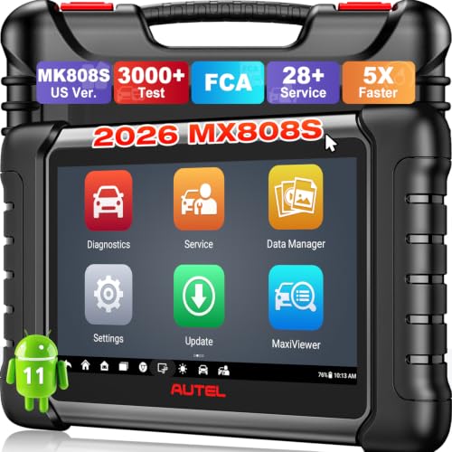
- 🔥🔥🔥【2026 AUTEL FLAGSHIP MK900BT MK900-BT, NEW...
- 🚗【3000+ ACTIVE TESTS (50➡3000+), SAME AS MS...
- 🚗【40+ HOT SERVICES FOR 150 MAKES (28+➡40+)】Full...
- 🚗【OE ALL SYSTEM DIAGNOSE, AUTO SCAN 2.0: SCAN LICENSE...

- 📌【We are Here for You】Dear valued customer, please be...
- 🚀【5X Faster Next-Level Hardware, Same as MK900/ MX...
- 🔥【3000+ Active Tests = MK900/MK900BT but...
- 📢【2026 U.S. Version, All-in-One as MK808S/ MK808Z...
- 🔥【28+ Hot Services for 150+ Brands】Same as MaxiCOM...
If the PDF is very large, it may not load in the preview below.
Some older TSBs had multiple PDFs — visit the NHTSA Website to view all PDFs.
If the TSB PDF does not show, download or view it on the NHTSA Website.
Click on the (+) Plus Sign
Then Click on Associated Document(s)
Search NHTSA Database for Recalls
Search NHTSA Database for Vehicle Investigations
View Latest Vehicle Investigations
Search NHTSA Database for Vehicle Complaints
View Latest Vehicle Complaints
TSB/Document ID: TP-H633 Rev I
Replacement Service Bulletin Number:
MFR Communication Date: 2019-03-01
MFR Internal Campaign ID/Software Version:
Communication Type: Service Bulletin/Repair Instructions
NHTSA Components: ELECTRONIC STABILITY CONTROL:AUTOMATIC (ASC)
MFR Component System:
MFR Component Subsystem:
Previous TSB | Next TSB |

- [Notice] When you receive a used device, it may be a customer return resold by Amazon without inspection. You can exchange it for a new one through Amazon. As this situation is unavoidable, we sincerely apologize. For any issues, contacting us via Amazon's "Messages" is the best way. THINKSCAN 689BT Bidirectional Scan Tool Can Be Used Immediately After It is Turned On, Without Complicated Registration Process, Which is More Convenient & Quick.
- Full Bi-Directional Control & 3000+ Active Tests: Take control and test components like actuators, fuel injectors, relays, and cooling fans in real time. You’ll quickly see if the problem is in the part itself or the control module — saving you hours of guesswork and frustrating trial-and-error.
- Advanced ECU Coding Capabilities: Handle module matching and hidden feature activation with confidence. When you replace an ECU or want to customize settings, this obd2 scanner diagnostic bi directional tool gives you the professional-level capabilities you need without the dealership price tag.
- 34+ Useful Reset and Maintenance Functions: Complete everyday service tasks smoothly with a wide range of helpful reset and maintenance functions. Whether you’re keeping up with regular upkeep or tackling a specific job, this scanner makes maintenance simpler and less stressful for both DIYers and pros.
- Comprehensive Full System Diagnostics: Diagnose every major system — Engine, Transmission
 , ABS, SRS, TPMS, and more — all in one place. Finally stop wondering if you’re missing something important; get the full picture and clear codes with ease.

- Top Reasons to Choose the D7S OBD2 Scanner: XTOOL D7S car scan tool, an upgrade of XTOOL D7, offers comprehensive features for automotive technicians, workshops, and DIY enthusiasts 1. Upgraded Hardware: 2+64GB memory, rear camera, intuitive interface, foldable bracket 2. Complete Diagnostics: FCA Autoauth, OE-level all system scan, 39+ maintenance services, 4K+ bidirectional, CANFD/DoIP protocol 3. Advanced Capabilities: ECU coding, PMI functions 4. Wide Compatibility: Support 10,000+ models, covering 99% vehicle brands 5. Multi-language: Available in 22+ languages, No IP Restrictions 6. 3-Year Updates: Save 300 bucks on software updates for the latest features and optimizations
- 2026 Upgraded D7S Car Scanner Features: The newly 2026 D7S V2.0 scanner for car brings exciting features for advanced vehicle diagnostics and enhanced user experience 1. FCA AutoAuth: Now supports FCA SGW module for Chrysler, for Jeep, for Dodge (2018+), for Fiat (2017+), enabling faster vehicle communication without gateway restrictions 2. PMI (Offline ECU Programming): Allows for Ford, for Lincoln, and for Mazda ECU programming for new modules 3. Optimized Diagnostic Report 2.0: Personalized reports with logos and customer info for auto shops. Note: Compatibility varies by cars, please check before order
- Cost-effective ECU Coding Scan Tool for Specific Brands: Enhance your vehicle's performance with XTOOL D7S! This obd2 scanner all systems bidirectional offers advanced capabilities at an affordable price, supports online for BMW, for Benz and offline for BENZ, for MIT, along with PMI functions for Ford, for Mazda, and for Lincoln. Ideal for technicians and DIY enthusiasts, this automotive scanner diagnostic tool optimizes vehicle performance and enhances the driving experience. Note: Not for all cars and modules, please send car VIN to check the compatibility before purchase
- OE All System Diagnostic & 8 Pids Graphing: XTOOL D7S is a comprehensive all system bi directional obd2 scanner that delivers dealer-level diagnostics, completely controlling over your vehicle’s performance and health. This automotive scan tool can read and clear DTCs, view live data and ECU information, retrieve freeze frames, and perform active tests and full obd2 functions. This bi-directional scan tool can can identify your vehicle's make, model, and year information with just one click and show up to 8 PIDs live data with options for CSV viewing, playback, and recording for in-depth analysis. It is easy-to-use for both professionals and beginners, helping pinpoint issues efficiently
- 3 Years Software Update, Value for Money: With 3 years of software updates and 22+ languages(no IP restrictions), XTOOL D7S auto scanner code scanner ensures ongoing compatibility for the latest car models and improved diagnostic functions. This all system vehicle diagnostic scanner comes with a 30-day return policy and a 24-month repair for dependable performance. XTOOL are dedicated to your satisfaction, so enjoy seamless support and lifetime expert assistance. Should you encounter any issues or concerns, don’t hesitate to reach out XTOOL. D7S with newest update with 22 languages freely transfer without authorization, check details from setting-language or from XTOOL

- 【✅Compared to BOSSCOMM IF742, IF745 Offers Full-System Diagnostics】The BOSSCOMM IF745 car diagnostic scanner is an upgraded model of IF742. In addition to supporting all OBD2 Code Reader functions and 6 reset options (ABS/EPB/SAS/BMS/Oil/Throttle), it expands diagnostics from 4 systems (Check Engine/ABS/SRS/Transmission) to vehicle All systems, including Steering, Suspension, and Body Electronics. This provides deeper, more comprehensive diagnostic capabilities.
- 【✨6 Essential Resets: ABS Bleeding, Oil, EPB, SAS, Throttle, BMS】The BOSSCOMM IF745 obd2 scanner diagnostic tool swiftly purges air from brake lines to restore braking sensitivity, fine-tunes maintenance cycles to eliminate false alerts, resolves parking brake issues with one-click control, recalibrates steering sensors for stability, optimizes engine idling/acceleration for smoother performance, and deeply resets battery systems to extend lifespan and range via precise parameter adjustments.❗NOTE: Does NOT support bidirectional control, coding, or programming.
- 【✨Deep Diagnostics for All Vehicle System Modules】Beyond code reading/clearing and ECU information retrieval, our all-in-one data stream feature lets you inspect all current fault codes and their locations across the vehicle’s systems. This vehicle code reader helps you turn off dashboard warning lights and perform a comprehensive self-check of your car at home—no more back-and-forth trips to the repair shop or hefty inspection fees.
- 【✨10 OBD2 Functions】The BOSSCOMM IF745 scan tool’s DTC Lookup instantly translates fault codes into user-friendly explanations, its I/M Readiness feature streamlines emissions testing with a single tap, and Freeze Frame lets you pinpoint the exact moment of a fault for in-depth root-cause diagnosis. Combined with a live data dashboard and advanced diagnostics (O2S, OBMon, EVAP), it delivers comprehensive insights for confident troubleshooting.
- 【✨10,000+ Car Models, AutoVIN, 13 Languages】The BOSSCOMM IF745 vehicle scanner diagnostic tool covers 73+ global car brands and offers support in 13 languages, making it perfect for DIYers, auto mechanics, or as a thoughtful gift. With a single-click AutoVIN feature, it instantly retrieves vehicle serial numbers, streamlining diagnostics for users globally. This adaptable tool balances user-friendliness with precision, catering to both personal and professional requirements.✅Unsure about compatibility? Compatibility will vary on vehicles' model and year, pls reach us via 📧 [email protected] 📧 before purchase.
This product presentation was made with AAWP plugin.