
NHTSA ID Number: 10162714
Manufacturer Communication Number: 17730-319 Rev A
TSB/Document Date: 2019-07-15
Summary
Operation Name: Hendrickson Truck Commercial Vehicle Systems Document Name: Technical Procedure - AIRTEK Front Air Suspension System for Tiffin Motorhome Chassis Summary: This document provides preventive maintenance, service, repair and rebuild instructions for Hendrickson AIRTEK front suspension and axle systems equipped on Tiffin Motorhome Chassis vehicles.
7 8
¾" Locknut
RH Tie Rod End
ABS Sensor
Sleeve
Tie Rod Assembly
Lower Grease
Cap Assembly
LH Tie Rod End
AIR SPRING ASSEMBLIES MUST BE DEFLATED PRIOR TO LOOSENING ANY CLAMP GROUP HARDWARE.
UNRESTRICTED AIR SPRING ASSEMBLIES CAN VIOLENTLY SHIFT. DO NOT INFLATE AIR SPRING
ASSEMBLIES WHEN THEY ARE UNRESTRICTED. AIR SPRING ASSEMBLIES MUST BE RESTRICTED
BY SUSPENSION OR OTHER ADEQUATE STRUCTURE. DO NOT INFLATE BEYOND PRESSURES
RECOMMENDED BY AIR SPRING MANUFACTURER, CONTACT HENDRICKSON TECHNICAL SERVICES
FOR DETAILS. IMPROPER USE OR OVER INFLATION MAY CAUSE AIR SPRING ASSEMBLIES TO BURST,
CAUSING PROPERTY DAMAGE AND / OR SEVERE PERSONAL INJURY.
4. Exhaust the air from the air system as per the vehicle manufacturer’s instructions.
17730-319
43
Component Replacement
AIRTEK® for Tiffin Motorhome Chassis
5. Raise the vehicle.
6. Support the vehicle with frame stands.
THE INTEGRATED AXLE SPRING SEATS ON THE STEERTEK NXT AXLE ARE NON-SERVICEABLE. DO
NOT REMOVE, MODIFY OR REPLACE INTEGRATED FASTENERS, DOING SO CAN CAUSE STRUCTURAL
DAMAGE AND RESULT IN LOSS OF VEHICLE CONTROL, PROPERTY DAMAGE, SEVERE PERSONAL INJURY,
OR DEATH AND VOID ANY APPLICABLE WARRANTY.
7. Suspend the front axle with the shock absorbers attached.
8. Remove the front wheels, hubs, brake shoes, ABS sensors, and backing plate assembly.
9. Disconnect the drag link from the steering arm.
IF THE AIR SPRING IS TO BE RE-INSTALLED; CARE MUST BE TAKEN TO REMOVE DIRT AND DEBRIS
FROM THE PUSH-TO-CONNECT FITTING. FAILURE TO DO SO COULD RESULT IN THE PUSH-TO-CONNECT
FITTING FAILING TO SEAL WITH THE AIR LINE. INSPECT LOCK-TABS FOR DAMAGE OR CRACKS PRIOR TO
RE-INSTALLATION.
10. Unseat both of the air springs at the axle top pad.
11. Support the axle with a floor jack.
THE REPAIR OR RECONDITIONING OF SUSPENSION OR AXLE COMPONENTS IS NOT ALLOWED.
ANY SUSPENSION OR AXLE COMPONENTS FOUND TO BE DAMAGED OR OUT OF SPECIFICATIONS
MUST BE REPLACED. ALL MAJOR HENDRICKSON COMPONENTS ARE HEAT TREATED AND TEMPERED.
AIRTEK COMPONENTS CANNOT BE BENT, WELDED, HEATED, OR REPAIRED WITHOUT REDUCING THE
STRENGTH OR LIFE OF THE COMPONENT. FAILURE TO FOLLOW THESE GUIDELINES CAN CAUSE LOSS
OF VEHICLE CONTROL, POSSIBLE PERSONAL INJURY, DEATH, OR PROPERTY DAMAGE AND WILL VOID
APPLICABLE WARRANTIES.
12. Remove the lower shock mounting locknut, washer and spacer from the axle seat. Remove
the lower shock absorbers from the lower mounting bolts and push clear of leaf spring
assembly.
SERVICE HINT
If a clamp group nut fails to come off bolt, cut half way through the bolt with an abrasive cut off
wheel, taking care not to contact axle beam or other components. Using an impact wrench, spin
the locknut to fracture the bolt and remove.
13. Remove the ¾" clamp group fasteners and discard.
14. Lower the axle and remove from the vehicle.
■■
STEERTEK NXT AXLE (Removed from Chassis)
AXLE REMOVAL
1. Remove the tie rod assembly, see Tie Rod Disassembly in this section.
REMOVAL OF THE CAP SCREWS WILL ALLOW THE STEERING KNUCKLE TO SEPARATE FROM THE AXLE.
THE STEERING KNUCKLE MUST BE SUPPORTED BEFORE REMOVAL OF THESE TWO (2) CAP SCREWS.
FAILURE TO DO SO CAN CAUSE COMPONENT DAMAGE OR PERSONAL INJURY.
2. Remove the two 5/8" socket head cap screws from the steering knuckle assembly, see
Figure 9-11.
3. Remove the steering knuckle and thrust bearing.
4. After complete removal of the one side, repeat Steps 1 through 3 for the opposite side of
the axle.
5. Inspect the kingpin bushings for excessive wear. If worn, replace the kingpin bushings and
seals. See the Kingpin Bushing replacement instructions in this section.
Component Replacement
44
17730-319
AIRTEK® for Tiffin Motorhome Chassis
AXLE INSTALLATION
1. Place the new axle on the floor jack and position the axle under the vehicle, see Figure 9-12.
2. Raise the axle into position. Care must be taken at this point to ensure that the center bolt of
front leaf spring assembly is aligned properly with the axle spring seat, see Figure 9-12.
3. Install the galvanized liner between the leaf spring and the top pad, see Figure 9-12.
FIGURE 9-12
Top Pad
Galvanized
Liner
Center Bolt to be aligned
with the axle spring seat
Place floor jack in center of axle
4. Install the top pad with the directional identification facing correctly on the vehicle, See Figure 9-13.
FIGURE 9-13
Directional
Identification
5. Install the new ¾" clamp group fasteners. Snug the bolts, DO NOT
tighten to the specified torque at this time.
6. Ensure that the clamp groups are properly aligned and the bolts
are seated in the top pad, and the top pad is centered on the axle
spring seat, see Figures 9-14 and 9-15.
7. See additional Air Spring Cautions and Warnings in the Important Safety Notice Section of this
publication prior to inflating or deflating the suspension system.
FIGURE 9-14
FIGURE 9-15
FIGURE 9-16
IMPORTANT
IMPORTANT
Ensure that the ¾" Clamp Bolts
are seated properly in the Top Pad
Ensure that Axle
Clamp Group is
properly aligned
¾" Clamp Group Locknuts
Tightening Torque
295 ± 10 ft. lbs. (400 ± 13 Nm)
17730-319
45
Component Replacement
AIRTEK® for Tiffin Motorhome Chassis
8. Engage the air springs into the top pad. The bottom of the air spring snaps to the top pad.
9. Install the lower shock absorber connection (if removed). Install the lower shock fasteners and
tighten to 130 ± 5 foot pounds torque.
10. Install the steering knuckles as per the Steering Knuckle Assembly instructions in this section.
11. Install the tie rod assembly.
12. Install the 7⁄8" hardened washers on the Ackermann arm and the castle nuts. Tighten the castle
nuts to 185 foot pounds, then rotate until the first castle slot lines up with the cotter pin
bore in the tie rod end. DO NOT back off the nut for cotter pin installation.
13. Install the tie rod end cotter pins.
14. Connect the drag link in the steering arms.
15. Install the castle nut to install the steering arm. Tighten the castle nut to 185 foot pounds,
then rotate until the first castle slot lines up with the cotter pin bore in the drag link. DO NOT
back off nut for cotter pin installation.
16. Install the drag link cotter pin.
17. Install the brake backing plate assemblies and ABS sensor.
18. Install the brakes, hubs, and wheels as per manufacturer’s guidelines.
19. Fill the hubs with the proper lubricant (see manufacturer’s guidelines for recommended
lubrication specifications).
20. Grease the front steering components as per lubrication guidelines in the Preventive
Maintenance Section of this publication.
21. Raise the vehicle and remove the frame stands.
22. Lower the vehicle.
23. Inflate the suspension to normal ride height as per the vehicle manufacturer’s specifications.
24. Tighten the ¾" clamp group locknuts evenly in 50 foot pounds increments to 295 ± 10 foot
pounds torque in the proper sequence to achieve uniform bolt tension, see Figure 9-16.
25. Check the ride height and adjust if necessary as per the vehicle manufacturer’s specifications.
26. Remove the wheel chocks.
■■
STEERING KNUCKLE DISASSEMBLY
See tools needed to remove and install kingpin bushing under the Special Tools Section of this
publication.
The steering knuckle disassembly and assembly includes the Kingpin Preparation and
Measurement and Kingpin Bushing Removal process.
FIGURE 9-17
1. Place the vehicle on level floor.
2. Chock the wheels.
3. Raise the frame.
4. Support the vehicle with frame stands.
5. Remove the wheel and hub assembly.
6. Remove the brake components from steering
knuckle.
Lightly tap the side
of Ackermann arm to
loosen the tie rod end
7. Remove the tie rod assembly.
SERVICE HINT
Lightly tap the side of the Ackermann arm with a mallet to separate the tie rod end from the
Ackermann arm, see Figure 9-17.
8. Remove the drag link from the knuckle if necessary.
Component Replacement
46
17730-319
AIRTEK® for Tiffin Motorhome Chassis
FIGURE 9-18
REMOVAL OF THE CAP SCREWS WILL
A L LO W T H E S T E E R I N G K N U C K L E
T O S E PA R AT E F R O M T H E A X L E .
THE STEERING KNUCKLE MUST BE
SUPPORTED BEFORE REMOVAL OF
THESE TWO (2) CAP SCREWS. FAILURE
TO DO SO CAN CAUSE COMPONENT
DAMAGE OR PERSONAL INJURY.
Socket Head Cap Screw
9. Remove the two (2) socket head
cap screws that connect upper
kingpin connection to the steering
knuckle, see Figure 9-18.
10. Remove the lower steering knuckle
from the kingpin by sliding it down
the kingpin.
11. Remove the upper steering knuckle by sliding it up and off the kingpin.
■■
KINGPIN PREPARATION AND MEASUREMENT
CLEANING GROUND AND POLISHED PARTS
■■
Use a cleaning solvent to clean ground or polished parts and surfaces. DO NOT USE
GASOLINE.
■■
DO NOT clean ground or polished parts in a hot solution tank or with water, steam, or
alkaline solutions. These solutions will cause corrosion of the parts.
DRYING THE CLEANED PARTS
■■
Parts must be dried immediately after cleaning. Dry the parts with clean paper towels,
clean rags, or compressed air. DO NOT dry bearings by spinning with compressed air.
Damage to the bearings will result.
PREVENTING CORROSION ON CLEANED PARTS
■■
Apply a light coating of oil to all cleaned and dried parts that are going to be reused. DO
NOT apply oil to the brake lining or the brake drums. If parts are to be stored, apply an
effective rust inhibitor to all surfaces.
TO HELP PREVENT SERIOUS EYE INJURY, ALWAYS WEAR PROPER EYE PROTECTION WHEN YOU
PERFORM VEHICLE MAINTENANCE OR SERVICE.
SOLVENT CLEANERS CAN BE FLAMMABLE, POISONOUS AND CAUSE BURNS. TO HELP AVOID SERIOUS
PERSONAL INJURY, CAREFULLY FOLLOW THE MANUFACTURER’S PRODUCT INSTRUCTIONS AND
GUIDELINES AND THE FOLLOWING PROCEDURES:
■■ WEAR PROPER EYE PROTECTION.
■■ WEAR CLOTHING THAT PROTECTS YOUR SKIN.
■■ WORK IN A WELL VENTILATED AREA.
■■ DO NOT USE GASOLINE, SOLVENTS OR OTHER MATERIALS THAT CONTAIN GASOLINE THAT CAN
EXPLODE.
■■ HOT SOLUTION TANKS OR ALKALINE SOLUTIONS MUST BE USED CORRECTLY. FOLLOW THE
MANUFACTURER’S RECOMMENDED INSTRUCTIONS AND GUIDELINES CAREFULLY TO HELP
PREVENT PERSONAL ACCIDENT OR INJURY.
17730-319
47
Component Replacement
AIRTEK® for Tiffin Motorhome Chassis
DO NOT USE HOT SOLUTION TANKS OR WATER AND ALKALINE SOLUTIONS TO CLEAN GROUND OR
POLISHED PARTS. DAMAGE TO THE PARTS WILL RESULT.
THE STEERTEK NXT HAS A UNIQUE AXLE. THE KINGPIN IS CRYOGENICALLY INSTALLED IN THE AXLE.
THE KINGPIN IS A NON-REPLACEABLE COMPONENT OF THE AXLE ASSEMBLY. DO NOT TRY TO REMOVE
THE KINGPIN. DOING SO WILL DAMAGE THE AXLE AND MAY CAUSE LOSS OF VEHICLE CONTROL,
PERSONAL INJURY OR PROPERTY DAMAGE. IF THE KINGPIN SHOWS SIGNS OF MOVEMENT, CONTACT
HENDRICKSON PRODUCT ENGINEERING - TECH SERVICES.
1. Prepare and polish the kingpin by removing all grease and excess debris using a fine grit (220 grit
or higher) emery cloth and parts solvent, see Figures 9-19 through 9-22.
2. Inspect the kingpin for wear or damage. Use a micrometer and measure the upper and lower
kingpin in two locations. Positions must be 90º opposed from each other. If the kingpin has less
than 1.802" diameter, replacement of the axle is necessary, see Figures 9-23 through 9-26.
Kingpin minimum dimension is 1.802"
Component Replacement
FIGURE 9-19
FIGURE 9-20
FIGURE 9-21
FIGURE 9-22
FIGURE 9-23
FIGURE 9-24
48
17730-319
AIRTEK® for Tiffin Motorhome Chassis
FIGURE 9-25
■■
FIGURE 9-26
KINGPIN BUSHING REMOVAL
You will need:
■■ A hydraulic shop press with a minimum forcing capacity of 2.5 tons (or use an arbor press)
■■ Adjustable straight flute reamer tool, see Special Tool Section in this publication
■■ Kingpin Bushing Driver, Receiving and Remover / Installer Tools, see Special Tool Section in this
publication
BEFORE APPLYING HYDRAULIC PRESSURE TO ANY TOOLING SET-UP, ALWAYS CHECK TO ENSURE THE
PRESS PLATE, ADAPTERS, AND COMPONENTS BEING WORKED ON ARE POSITIONED PROPERLY, I.E.
“IN LINE” WITH THE RAM OF THE PRESS. IMPROPER POSITIONING CAN CAUSE PERSONAL INJURY OR
COMPONENT DAMAGE.
PRIOR TO APPLYING HYDRAULIC PRESSURE TO REMOVE OR INSTALL THE KINGPIN BUSHING, SUPPORT
THE LOWER STEERING KNUCKLE AS SHOWN IN FIGURES 9-27 AND 9-28. IMPROPER SUPPORT TO THE
STEERING KNUCKLES CAN CAUSE COMPONENT DAMAGE.
1. Remove the threaded grease cap and grease zerk.
2. Ensure that each part of the steering knuckle assembly is squarely supported on the receiving
tool before applying hydraulic pressure to press out the kingpin bushings, see Figure 9-27
through 9-29.
3. Place the STEERTEK NXT installer / remover tool in the steering knuckle / kingpin bore. Then
place the kingpin bushing push-out tool on top of the installer / remover.
4. Press out the kingpin bushing.
5. Clean the parts and inspect for reassembly.
FIGURE 9-27
17730-319
FIGURE 9-28
FIGURE 9-29
49
Component Replacement
AIRTEK® for Tiffin Motorhome Chassis
■■
STEERING KNUCKLE BORE MEASUREMENT
Complete the following steering knuckle bore inspection and the measurement instructions prior
to installing the kingpin bushing.
1. Measure the upper knuckle bore inside diameter at two locations. Always use an inside
micrometer or a telescoping gauge when taking a knuckle bore measurement. Some outof-roundness at the top and bottom of the bore edges is acceptable. Steering knuckle bore
diameter is 1.938" ± 0.003".
2. Measure the upper and lower bore in two positions and at two locations.The two positions must
be 90º opposed from each other, see Figures 9-30 through 9-32 If the average measurement is
more than the knuckle bore maximum diameter specification, replace the knuckle.
FIGURE 9-30
■■
FIGURE 9-31
FIGURE 9-32
KINGPIN BUSHING INSTALLATION
You will need:
■■ A hydraulic shop press with a minimum forcing capacity of 2.5 tons.
■■ Kingpin Bushing Driver, Receiving and Remover / Installer Tools, see Special Tool Section in this
publication
■■ Adjustable straight flute reamer, see Special Tools Section in this publication.
BEFORE APPLYING HYDRAULIC PRESSURE TO ANY TOOLING SET-UP, ALWAYS CHECK TO BE SURE
THE PRESS PLATE, ADAPTERS, AND COMPONENTS BEING WORKED ON ARE POSITIONED PROPERLY,
I.E. “IN LINE” WITH THE RAM. IMPROPER POSITIONING CAN CAUSE PERSONAL INJURY OR
COMPONENT DAMAGE.
1. Install the lower or upper steering knuckle in the press. Ensure that each part of the steering
knuckle assembly is squarely supported on the receiving tool before applying hydraulic pressure to press in the kingpin bushings.
2. Always install the kingpin bushing from the machined side (axle side) of the lower steering
knuckle using a bushing driver, (see driver specifications in the Special Tools Section of this
publication). Press in bushing to a depth of no less than 15⁄64" (0.236") or 6 millimeters and no
more than 5⁄16" (0.32") or 8 millimeters, see Figures 9-33 and 9-35.
3. Following this procedure it is necessary to ream the kingpin bushings to fit the kingpins, see
Kingpin Bushing Reaming Instructions in this section.
Component Replacement
50
17730-319
AIRTEK® for Tiffin Motorhome Chassis
FIGURE 9-33
■■
FIGURE 9-34
FIGURE 9-35
KINGPIN BUSHING REAMING
REAM THE KINGPIN BUSHINGS WITH AN ADJUSTABLE STRAIGHT FLUTE REAMER. DO NOT HONE OR
BURNISH THE KINGPIN BUSHINGS. HONING OR BURNISHING WILL DAMAGE THE BUSHINGS AND VOID
ANY APPLICABLE WARRANTY.
WHEN INSTALLING STEERING KNUCKLE COMPONENTS IN A VISE IT IS NECESSARY TO PROTECT THE
MACHINED SURFACES FROM GOUGES OR MARRING BY USING BRASS JAWS. FAILURE TO DO SO CAN
CAUSE PREMATURE PART DAMAGE, DAMAGE TO THE STEERING KNUCKLE COMPONENTS, LOSS OF
WARRANTY, LOSS OF VEHICLE CONTROL, CAUSING PERSONAL INJURY OR PROPERTY DAMAGE.
4. Install the lower steering knuckle assembly in a vise with brass jaws.
SERVICE HINT
It is acceptable to mount the knuckle components in a vise either vertically or horizontally when
performing the reaming procedure.
5. Install the reamer into the lower steering knuckle until the blades touch the kingpin bushing.
6. Rotate the reamer with light downward pressure. Rotate the reamer smoothly. DO NOT apply
too much pressure, see Figures 9-36 and 9-37.
FIGURE 9-36
FIGURE 9-37
7. Slide the reamer out of the lower steering knuckle assembly. If it is necessary to remove the
reamer from the top, rotate the reamer opposite of cutting rotation.
8. Clean and remove all kingpin bushing material from the knuckle assembly. Take special attention to remove material from the grease channels and dimples.
17730-319
51
Component Replacement
AIRTEK® for Tiffin Motorhome Chassis
9. Clean the 5/8" brake backing plate bolts with a wire wheel and run a tap through the threads
of the upper kingpin connection / steering arm and then flush out with brake cleaner and dry
with compressed air.
PRIOR TO INSTALLATION ENSURE THAT ALL RESIDUAL LOCTITE MATERIAL IS REMOVED FROM THE
MOUNTING BOLTS AND THE THREAD BORES IN THE UPPER KINGPIN CONNECTION OR STEERING
ARM, AND NEW LOCTITE 277 OR EQUIVALENT IS APPLIED TO HELP ENSURE THAT THE BOLTS SUSTAIN
THE PROPER TORQUE REQUIREMENT. FAILURE TO DO SO CAN CAUSE LOSS OF VEHICLE CONTROL
RESULTING IN PERSONAL INJURY OR PROPERTY DAMAGE.
FIGURE 9-38
NOTE
FIGURE 9-39
The Hendrickson Genuine part,
socket head cap screw comes with
a pre-applied Loctite compound.
10. Install the steering arm and
upper kingpin connection on
the kingpin.
11. Check for the proper fit by rotating the knuckle assembly back
and forth to verify there is no
binding on the kingpin, see
Figures 9-38 and 9-39.
12. If the bushing is too tight repeat
Steps 1 through 8 until the
proper clearance is achieved.
NOTE
Bushing size is to be 0.001" larger than the kingpin size.
■■
KINGPIN SEAL INSTALLATION
1. Place the steering knuckle assembly in a vise with brass jaws or place on a suitable workbench. The steering knuckle will have the machined surface facing up (axle side up).
2. Lay the kingpin seal into the bore of the steering knuckle. The seal lip should face outward or
toward the axle, see Figure 9-40.
3. Use a kingpin bushing driver tool (see Special Tool Section) and press seal firmly into the
steering knuckle assembly.
4. Double Lip design, see Figure 9-41. Install the kingpin seal until it bottoms out in the kingpin bore.
FIGURE 9-40
Component Replacement
FIGURE 9-41
52
17730-319
AIRTEK® for Tiffin Motorhome Chassis
■■
STEERING KNUCKLE ASSEMBLY
After replacement of the kingpin bushings it is necessary to re‑assemble the steering knuckle assemblies. DO
NOT substitute aftermarket components when servicing.
The left and right side of the STEERTEK NXT axle for Tiffin
Motorhome Chassis is equipped with steel roller thrust
bearings, see Figure 9-42.
FIGURE 9-42
Top View of Roller Bearing
1. Install the thrust bearing on the lower kingpin with the
seal facing up toward axle (the black seal will designate the top side), see Figure 9-42.
Seal
2. Install the shim, if equipped, on the upper kingpin.
3. Pack the bushing dimples on the upper and lower steering knuckles with multi purpose
Lithium based grease (NLGI Grade 2) before installation.
4. Install the upper steering knuckle on the upper arm kingpin.
5. Install the lower steering knuckle on the lower kingpin and install the old socket head cap
screws loose into the top two threaded holes.
6. Install a bottle jack under the lower knuckle and slightly raise the knuckle until it is possible to
thread in the (3) brake backing plate bolts by hand. These are for guide purposes only.
FIGURE 9-43
7. Snug the two socket head cap screws.
8. Lower the bottle jack so that all the vertical
end play is on the underside of the axle.
9. Affix a magnetic base dial indicator on the
axle and place the tip of the dial indicator on
top of the knuckle assembly, see Figure 9-43.
10. Zero the dial indicator.

- rv toilet brush: Engineered specifically for RVs, this brush...
- Compact Wall-Mounted Toilet Brush: With its space-saving...
- silicone toilet brush: This brush is designed for thorough...
- Wall-Mounted Toilet Brush for RV Travel: The brush head is...
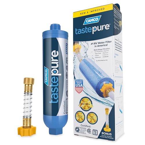
- Advanced 6-Step Filtration Technology: Discover the...
- Certified Lead-Free: This camping water filter is...
- Access to Pure, Great-Tasting Water: Enjoy clean water...
- Patented Technology & Made in the USA: This in-line water...
- Versatile Applications: Easily attach this multi-purpose...

If the PDF is very large, it may not load in the preview below.
Some older TSBs had multiple PDFs — visit the NHTSA Website to view all PDFs.
If the TSB PDF does not show, download or view it on the NHTSA Website.
Click on the (+) Plus Sign
Then Click on Associated Document(s)
Search NHTSA Database for Recalls
Search NHTSA Database for Vehicle Investigations
View Latest Vehicle Investigations
Search NHTSA Database for Vehicle Complaints
View Latest Vehicle Complaints
TSB/Document ID: 17730-319 Rev A
Replacement Service Bulletin Number:
MFR Communication Date: 2019-03-01
MFR Internal Campaign ID/Software Version:
Communication Type: Service Bulletin/Repair Instructions
NHTSA Components: SUSPENSION
MFR Component System:
MFR Component Subsystem:
Previous TSB | Next TSB |

- [Notice] When you receive a used device, it may be a customer return resold by Amazon without inspection. You can exchange it for a new one through Amazon. As this situation is unavoidable, we sincerely apologize. For any issues, contacting us via Amazon's "Messages" is the best way. THINKSCAN 689BT Bidirectional Scan Tool Can Be Used Immediately After It is Turned On, Without Complicated Registration Process, Which is More Convenient & Quick.
- Full Bi-Directional Control & 3000+ Active Tests: Take control and test components like actuators, fuel injectors, relays, and cooling fans in real time. You’ll quickly see if the problem is in the part itself or the control module — saving you hours of guesswork and frustrating trial-and-error.
- Advanced ECU Coding Capabilities: Handle module matching and hidden feature activation with confidence. When you replace an ECU or want to customize settings, this obd2 scanner diagnostic bi directional tool gives you the professional-level capabilities you need without the dealership price tag.
- 34+ Useful Reset and Maintenance Functions: Complete everyday service tasks smoothly with a wide range of helpful reset and maintenance functions. Whether you’re keeping up with regular upkeep or tackling a specific job, this scanner makes maintenance simpler and less stressful for both DIYers and pros.
- Comprehensive Full System Diagnostics: Diagnose every major system — Engine, Transmission, ABS, SRS, TPMS, and more — all in one place. Finally stop wondering if you’re missing something important; get the full picture and clear codes with ease.

- Top Reasons to Choose the D7S OBD2 Scanner: XTOOL D7S car scan tool, an upgrade of XTOOL D7, offers comprehensive features for automotive technicians, workshops, and DIY enthusiasts 1. Upgraded Hardware: 2+64GB memory, rear camera, intuitive interface, foldable bracket 2. Complete Diagnostics: FCA
 Autoauth, OE-level all system scan, 39+ maintenance services, 4K+ bidirectional, CANFD/DoIP protocol 3. Advanced Capabilities: ECU coding, PMI functions 4. Wide Compatibility: Support 10,000+ models, covering 99% vehicle brands 5. Multi-language: Available in 22+ languages, No IP Restrictions 6. 3-Year Updates: Save 300 bucks on software updates for the latest features and optimizations
 - 2026 Upgraded D7S Car Scanner Features: The newly 2026 D7S V2.0 scanner for car brings exciting features for advanced vehicle diagnostics and enhanced user experience 1. FCA AutoAuth: Now supports FCA SGW module for Chrysler, for Jeep, for Dodge (2018+), for Fiat (2017+), enabling faster vehicle communication without gateway restrictions 2. PMI (Offline ECU Programming): Allows for Ford, for Lincoln, and for Mazda ECU programming for new modules 3. Optimized Diagnostic Report 2.0: Personalized reports with logos and customer info for auto shops. Note: Compatibility varies by cars, please check before order
- Cost-effective ECU Coding Scan Tool for Specific Brands: Enhance your vehicle's performance with XTOOL D7S! This obd2 scanner all systems bidirectional offers advanced capabilities at an affordable price, supports online for BMW, for Benz and offline for BENZ, for MIT, along with PMI functions for Ford, for Mazda, and for Lincoln. Ideal for technicians and DIY enthusiasts, this automotive scanner diagnostic tool optimizes vehicle performance and enhances the driving experience. Note: Not for all cars and modules, please send car VIN to check the compatibility before purchase
- OE All System Diagnostic & 8 Pids Graphing: XTOOL D7S is a comprehensive all system bi directional obd2 scanner that delivers dealer-level diagnostics, completely controlling over your vehicle’s performance and health. This automotive scan tool can read and clear DTCs, view live data and ECU information, retrieve freeze frames, and perform active tests and full obd2 functions. This bi-directional scan tool can can identify your vehicle's make, model, and year information with just one click and show up to 8 PIDs live data with options for CSV viewing, playback, and recording for in-depth analysis. It is easy-to-use for both professionals and beginners, helping pinpoint issues efficiently
- 3 Years Software Update, Value for Money: With 3 years of software updates and 22+ languages(no IP restrictions), XTOOL D7S auto scanner code scanner ensures ongoing compatibility for the latest car models and improved diagnostic functions. This all system vehicle diagnostic scanner comes with a 30-day return policy and a 24-month repair for dependable performance. XTOOL are dedicated to your satisfaction, so enjoy seamless support and lifetime expert assistance. Should you encounter any issues or concerns, don’t hesitate to reach out XTOOL. D7S with newest update with 22 languages freely transfer without authorization, check details from setting-language or from XTOOL

- 【✅Compared to BOSSCOMM IF742, IF745 Offers Full-System Diagnostics】The BOSSCOMM IF745 car diagnostic scanner is an upgraded model of IF742. In addition to supporting all OBD2 Code Reader functions and 6 reset options (ABS/EPB/SAS/BMS/Oil/Throttle), it expands diagnostics from 4 systems (Check Engine/ABS/SRS/Transmission) to vehicle All systems, including Steering, Suspension, and Body Electronics. This provides deeper, more comprehensive diagnostic capabilities.
- 【✨10 OBD2 Functions】The BOSSCOMM IF745 scan tool’s DTC Lookup instantly translates fault codes into user-friendly explanations, its I/M Readiness feature streamlines emissions testing with a single tap, and Freeze Frame lets you pinpoint the exact moment of a fault for in-depth root-cause diagnosis. Combined with a live data dashboard and advanced diagnostics (O2S, OBMon, EVAP), it delivers comprehensive insights for confident troubleshooting.
- 【✨Deep Diagnostics for All Vehicle System Modules】Beyond code reading/clearing and ECU information retrieval, our all-in-one data stream feature lets you inspect all current fault codes and their locations across the vehicle’s systems. This vehicle code reader helps you turn off dashboard warning lights and perform a comprehensive self-check of your car at home—no more back-and-forth trips to the repair shop or hefty inspection fees.
- 【✨6 Essential Resets: ABS Bleeding, Oil, EPB, SAS, Throttle, BMS】The BOSSCOMM IF745 obd2 scanner diagnostic tool swiftly purges air from brake lines to restore braking sensitivity, fine-tunes maintenance cycles to eliminate false alerts, resolves parking brake issues with one-click control, recalibrates steering sensors for stability, optimizes engine idling/acceleration for smoother performance, and deeply resets battery systems to extend lifespan and range via precise parameter adjustments.❗NOTE: Does NOT support bidirectional control, coding, or programming.
- 【✨10,000+ Car Models, AutoVIN, 13 Languages】The BOSSCOMM IF745 vehicle scanner diagnostic tool covers 73+ global car brands and offers support in 13 languages, making it perfect for DIYers, auto mechanics, or as a thoughtful gift. With a single-click AutoVIN feature, it instantly retrieves vehicle serial numbers, streamlining diagnostics for users globally. This adaptable tool balances user-friendliness with precision, catering to both personal and professional requirements.✅Unsure about compatibility? Compatibility will vary on vehicles' model and year, pls reach us via 📧 [email protected] 📧 before purchase.
This product presentation was made with AAWP plugin.