
NHTSA ID Number: 11034216
Manufacturer Communication Number: 76-05
TSB/Document Date: 2026-07-01
Summary
On certain Winnebago vehicles, performing a hard reset of the Xantrex inverter may change the “Battery Type” setting. If this setting is incorrect, the batteries may not charge properly, which may result in reduced performance. This campaign will also update the Xantrex inverter to the latest firmware version.
Service Campaign ID: 76 – 05 Xantrex Inverter Settings
Issued Date: June 11, 2026
Impacted Vehicles
Model Year
Rev.
Make
Model
Model Code(s) Floorplans
Built Dates
2025
1
View/Navion
IM524R, IM524T,
WM524R, WM524T
1/5/2024 – 5/19/2025
Reason for this Campaign
On certain Winnebago vehicles, performing a hard reset of the Xantrex inverter may change the “Battery
Type” setting. If this setting is incorrect, the batteries may not charge properly, which may result in
reduced performance. This campaign will also update the Xantrex inverter to the latest firmware version.
Dealer Campaign Responsibility
Perform this procedure on all subject vehicles currently in your inventory. DO NOT DELIVER ANY
SUBJECT UNITS TO A CUSTOMER UNTIL THIS CORRECTIVE ACTION HAS BEEN TAKEN.
Owner Notification
Owners will be notified a week after the issued date of this campaign.
Repair Procedure
An update to the inverter is necessary to ensure that a hard reset does not change the Battery Type
setting, which should remain set to Lithium. The Xantrex Inverter Firmware will also be updated to the
latest version. Refer to instruction sheet provided with parts kit or posted on the dealer portal.
Parts Information
Quantity
1
Parts Kit Number
SC785626705
Part Kit Description
Xantrex Pro Inverter Update
The part order should be placed as a Campaign Service order.
IMPORTANT
The Parts Kit consists of reusable tools. Only 1 kit is needed per dealer location!
Reimbursement
When the service has been completed, submit a warranty claim using the operation number and TIC
code listed below. If the vehicle is out of warranty, use service authorization 73G0430T when filing your
claim.
Labor Operation
Operation Number
05760599
Dealer Number
WG-007856
Xantrex Inverter Settings
Time Allowance
1.5
TIC Code
7605SB
FINAL CLAIMS MUST BE SUBMITTED BY DECEMBER 11, 2026
Xantrex Inverter Settings
Parts Kit Required
Classification
Service Campaign # 76-05
Part #
SC785626705
Description
XANTREX PRO INVERTER UPDATE
Condition
On certain Winnebago vehicles, if a hard reset of the Xantrex Inverter is performed, it can change the ‘Battery Type’ setting. If
the ‘Battery Type’ setting is incorrect the batteries may not charge properly, which can lead to reduced performance.
Correction
An update to the inverter is necessary to ensure that a hard reset does not change the Battery Type setting, which should
remain set to Lithium. As part of this campaign the inverter firmware will also be updated to the latest version.
Disclaimer: Read the entire instructions carefully before starting the procedure. If you have any questions, please contact the Winnebago Industries Technical
Service Department by calling 1-866-653-4329 or by email: [email protected] . This document is confidential and is intended for dealer use only.
Campaign: This campaign addresses Non-Safety-related conditions and provides recommended technical diagnosis and repair procedures. Apply this procedure to
the applicable vehicles.
Page 1 of 17
Parts/Kit Image Reference
Part/s Required – SC785626705
Shop Supplies
Kit Contains:
1. Screw gun/Screwdriver
2. 3/8” Socket with ¼” Drive
3. Socket Wrench
4. 1/4” Drive drill bit extension 4” – 6”
5. #2 Philips Bit
6. Laptop
7. Handheld Inspection Mirror
8. Flashlight
1. Configuration File & Xantrex OEM App Tool USB (328076-01-701)(1)
2. Programming Cable (32807601700) (1)
3. U1 V02-96 Blue Tag USB (328076-01-705)(1)
4. U3 V02-17 Red Tag USB (328076-01-704) (1)
IMPORTANT: Only 1 Parts Kit is required per dealer location!
1 Kit can be used to repair all applicable vehicles per dealer location.
Part/s Required
1.
2.
(Configuration File)
3.
(Xantrex OEM App Tool)
4.
For feedback on the accuracy of this document, email [email protected].
Page 2 of 17
Steps & Procedures (Part 1 – Inverter Settings)
A
Step 1 – Inverter Compartment Disassembly
Objective: Safely disassemble the inverter compartment (Passenger Side RH1) by removing the
closeout panel.
NOTE: DO NOT UNPLUG ANY CABLES/WIRES THAT ARE ALREADY CONNECTED INTO THE
INVERTER AT ANY POINT OF THIS PROCESS!
B
A. Turn the Inverter Disconnect to OFF before you relocate the inverter to access
the necessary ports.
B. Carefully remove the Passenger Side compartment closeout panel by
unscrewing the 4 bolts with a 3/8” socket and wrench and set panel aside to
avoid damage.
Step 2 – Inverter Power Activation
Objective: Activate the inverter by turning on the disconnect switch to enable its display and standby indicator light.
A. Turn the inverter disconnect switch to the "ON" position. The inverter display will light up, and a Green standby light
will illuminate.
A
A
For feedback on the accuracy of this document, email [email protected].
Page 3 of 17
Step 3 – Inverter Configuration
Step 3 : Part A: Download the Files from the ‘Xantrex OEM App Tool & RevBFX ’ USB
1) Create the 'Xantrex Files' Folder
Open File Explorer by pressing the Windows Key + E on your keyboard.
Click "Documents" from the left-hand sidebar menu.
Right-click empty space inside the Documents folder, select New, and then click Folder.
Label the folder by typing Xantrex Files and pressing Enter.
2) Copy the Files From the USB
Plug in the Configuration File & Xantrex OEM App Tool USB into an open USB port on the laptop.
Click "This PC" from the left-hand sidebar menu in File Explorer.
Double-click your USB drive under the "Devices and drives" section.
Locate the files named Configuration File (RevBFX) and the Xantrex
OEM App Tool.
Highlight both files, right-click them, and select Copy (or press Ctrl + C).
Navigate back to your newly created folder by clicking Documents in the
sidebar and double-clicking Xantrex Files folder.
Right-click empty space inside the new "Xantrex Files" folder and select Paste (or press Ctrl + V) to download
them to this location.
3) Safely Remove the USB
Safely eject the USB by right clicking the USB drive icon in the left-hand sidebar.
Select Eject from the drop-down menu.
Remove the USB from the laptop physical port once the system confirms it is safe.
For feedback on the accuracy of this document, email [email protected].
Page 4 of 17
Step 3: Part B: Load the Files and Configure
A. Open the OEM App Tool downloaded.
Ensure that the OEMAppTool is launched on your laptop to start the configuration process.
B. Using the mirror and a flashlight, Insert the cable’s RJ11 end (telephone-line side) into the REMOTE terminal on the Inverter.
Proper connection is crucial for communication between the device and the OEMCfgTool
For feedback on the accuracy of this document, email [email protected].
Page 5 of 17
C. Next, on your Laptop Screen Hit “Read”.
D. This action allows the software to retrieve the current settings of the inverter, establishing a baseline for any modifications.
NOTE: If you are having trouble connecting
the Laptop to the Inverter, there are 2 key
things you could verify:
1. Ensure that the RJ12 (phone cable) is securely
plugged into the "REMOTE" terminal rather
than the "BTS" terminal, as you may experience
connection issues due to this mistake.
2. If the RJ12 cable is correctly connected to the
"REMOTE" terminal but the laptop still fails to
connect, it is likely that the laptop's drivers need
to be updated.
For feedback on the accuracy of this document, email [email protected].
Page 6 of 17
A
Step 4 – Inverter Configuration - Continued
Objective: Reset Inverter Settings
A. On the OEM Tool screen, click on “RESET TO FACTORY DEFAULT”.
B. Click on “File” on the Top Left Corner. (See Figure 11 – Highlighted in Green)
Initiate the file management functions, leading to further configuration steps.
C. A Pop Up Will Appear, Click “OK”
Acknowledge the prompt to proceed with resetting the inverter.
D. Click on ”Load Configuration”. (See Figure 13 – Highlighted in Green)
Prepare to load specific configuration settings that are needed for your inverter’s
operation.
B
C
For feedback on the accuracy of this document, email [email protected].
D
Page 7 of 17
Step 5 – Inverter Configuration - Continued
Objective: Load Configuration
A. Next, verify on your screen all the locks in the status bar are turned off as shown above. Also verify the battery type states
“LifePO4” (Lithium).
For feedback on the accuracy of this document, email [email protected].
Page 8 of 17
B. Within the new Xantrex Files folder, click on the RevBFX file.
Selecting this file is essential as it contains the necessary parameters for your specific inverter model.
C. Click “Open”
This step finalizes the selection of the configuration file, preparing it for loading
C
For feedback on the accuracy of this document, email [email protected].
Page 9 of 17
Step 6 – Inverter Configuration - Continued
Objective: Apply Configuration Changes
A. Next, verify on your screen all the locks in the status bar are turned off as shown in Figure 17 Right-side column
”Locked Status”. Also verify the battery type states “LifePO4” (Lithium). (See Figure 17)
For feedback on the accuracy of this document, email [email protected].
A
Page 10 of 17
B. Click on “Set OEM Default”. Let it load for a couple of seconds. (Blue Arrow)
C. Click on “Reset to OEM Default”. Let it load for a couple of seconds. (Red Arrow)
Initiate the process to apply the factory preset configurations to the inverter. Allow a few seconds for this action
to be completed.
B/C
For feedback on the accuracy of this document, email [email protected].
Page 11 of 17
D
D. Once the Values are set and locks are no longer on, click on “Disconnect”.
(Green Arrow)
This step ensures that changes have been appropriately configured
before disconnecting the device.
E. After Clicking “Disconnect”, your screen should Clear itself and Reset
E
for the next Inverter. Ensure to Unplug the Programing Cable.
This action signifies that the configuration for the current
inverter is complete, and the tool is ready for use with another
device.
For feedback on the accuracy of this document, email [email protected].
Page 12 of 17
Step 7 – Inverter Configuration Checks
A. Manually Check the Battery Type Setting on the Inverter Display. This is crucial for operational integrity to verify the
battery type setting:
1. Press and Hold “OK” for 3 Seconds. This action initiates navigation through the inverter settings. (Red Outline)
2. Scroll Using “^” Until You Reach Screen 20. This specific action directs you to the relevant screen that displays
the battery type. (Green Outline)
3. If it reads “LFP”, Click on “ESC” and Move to the Following Steps. This indicates that the setting is correct,
allowing progression to the final steps. (Yellow Outline)
4. If it does NOT Read “LFP”, Contact Winnebago Technical Service at 1-866-653-4329.
B. Turn the Inverter Disconnect Switch Back to “OFF” (See Figure 23 – Green Circle). Ensure that the system is safely
powered down to protect against any electrical mishap during final reassembly.
A
For feedback on the accuracy of this document, email [email protected].
Figure 23
Page 13 of 17
Steps & Procedures (Part 2 – Firmware Update)
Step 1 – Turn ON the Inverter Disconnect
For feedback on the accuracy of this document, email [email protected].
Page 14 of 17
Step 3 – U1 Firmware Update
A. Using the mirror and flashlight, Insert the U1 V02 96
USB at the top USB Port of the inverter.
B. The LED at the USB port should start flashing within 1
minute. If the LED does not start flashing, pull the
stick out and re insert again and wait 1 minute). If the
LED still does not start flashing, contact Winnebago
Tech Service
C. You will hear a relay click on the inverter. This confirms
the update is initiating.
D. The update will take a few minutes to complete. The
inverter will reboot and the flashing will stop once
completed.
E. With the USB stick still in the inverter verify on the
Flashing Light Should be Here
Inverter display that it shows U1 V02 96.
F. Remove the U1 V02 96 USB stick.
Step 4 – Turn the Inverter OFF
Step 5 - Turn the Inverter Disconnect Switch Back to “OFF”
For feedback on the accuracy of this document, email [email protected].
Page 15 of 17
Step 6 – Turn the Inverter Back ON
a. Use the inverter switch to turn the inverter back on. This will flash for a second. (Doing this drains all the excess
power out of the capacitor).
Step 7 – Turn the Inverter OFF
Step 8 - Turn the Inverter Disconnect Switch Back to “ON”
For feedback on the accuracy of this document, email [email protected].
Page 16 of 17
Step 9 – U3 Firmware Update
A. Insert the U3 V02 17 USB stick on the same USB Inverter Port.
B. Use the inverter switch to turn the Inverter ON.
C. In about 30 seconds the LED light at the USB port will first turn orange and then
start flashing green (verify using the mirror). This will continue for up to 5 minutes.
(Wait until flashing stops, even if it takes longer than the 5 minutes.)
D. With the USB stick still in the inverter, verify the display reads U3 02 17. ( This may
take several seconds).
E. Remove the USB stick.
Note: After installing the U3 firmware, it may take up to 30 seconds to display on the
screen. If the inverter will not display U3 02 17 after the 30 seconds, remove USB stick
and use the inverter switch to turn off the inverter.
Wait 1 minute, then use the inverter switch to turn on the inverter and verify if the
display reads U3 02 17. If it still does not display U3 02 17, contact Winnebago Tech
Service.
Step 10 – Verify Updates
A. Turn the inverter disconnect and the inverter OFF for 1 minute.
B. Turn the inverter disconnect back ON.
C. Turn the inverter back ON.
D. Ensure the U1 02 96 and U3 02 17 firmware still shows on the display .
Toggle the Arrow button to the 3rd page to see the U1 update.
Toggle the arrow botton to the 4th page to see the U3 update.
Step 11 – Reinstall Panel
A. Carefully reinstall the Passenger Side’s compartment closeout panel by screwing back in the 4 bolts with a 3/8”
socket and wrench. This is the Final step in securing the inverter, ensuring it is protected and ready for operational
use.
For feedback on the accuracy of this document, email [email protected].
Page 17 of 17
To:
«CUSTOMER_NAME»
«CUSTOMER_ADDRESS_1»
«CUSTOMER_ADDRESS_2»
«CITY» «STATE» «ZIP»
THIS NOTICE APPLIES TO YOUR VEHICLE.
RE:
BODY SERIAL «BODY_SERIAL» CHASSIS SERIAL «CHASSIS_SERIAL»
June 2026
Dear Winnebago RV Owner,
When you purchased your new Winnebago RV, you also received our commitment to provide you with a
quality product and our dedication to continuing customer satisfaction. In keeping with this commitment, we are
notifying you of a service campaign that may affect your Winnebago RV.
Reason for This Campaign
On certain Winnebago View and Navion coaches, performing a hard reset of the Xantrex Inverter may change the
‘Battery Type’ setting. If the ‘Battery Type’ setting is incorrect the batteries may not charge properly, which can lead to
reduced performance.
What We Will Do
Winnebago Motorhomes has released Field Service Campaign 76-05 authorizing your dealer to update the Xantrex
inverter to ensure that a hard reset does not change the ‘Battery Type’ setting. As part of this campaign the inverter
firmware will also be updated to the latest version.
What You Should Do
Please contact your authorized Winnebago motorhome dealer to schedule an appointment to have this repair
performed. The actual repair will take approximately 1.5 hours. However, due to service scheduling requirements,
your dealer may need your coach for a longer period of time.
To locate a Winnebago Motorhome dealer, please visit www.winnebago.com and click on the “Locate Dealer” link.
This remedy will be performed at no charge to you through December 11, 2026.
ADDRESS OR VEHICLE CHANGES
If you have changed your address, sold, or traded your vehicle since purchase, provide the updated information at
www.winnebago.com/owners/owner-resources/second-owner-registration
Winnebago Motorhomes
Forest City, Iowa 50436
[email protected] | (800) 537-1885 | www.winnebago.com
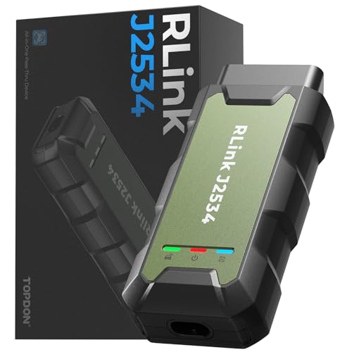
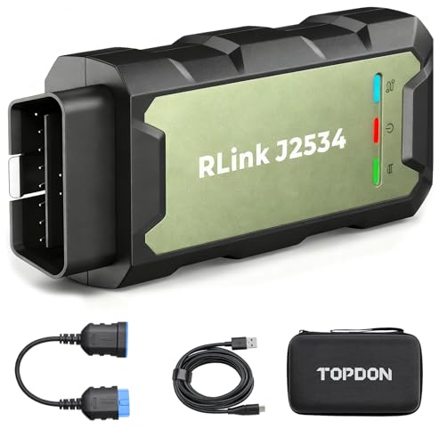
- Advanced VCI Box, Industry-leading J2534 Pass-Thru...
- High-Speed OEM-Level Diagnostics & Programming: Unlock true...
- Coverage for 17 Car Brands & Ultra Reliability: Works...
- User-Friendly RLink Platform & Expert Support: TOPDON’s...
- 6.6 ft USB-C Cable & Portable Storage Case: The RLink J...
Last update on 2026-06-23 / Affiliate links / Images from Amazon Product Advertising API
If the PDF is very large, it may not load in the preview below.
Some older TSBs had multiple PDFs — visit the NHTSA Website to view all PDFs.
If the TSB PDF does not show, download or view it on the NHTSA Website.
Click on the (+) Plus Sign
Then Click on Associated Document(s)
Search NHTSA Database for Recalls
Search NHTSA Database for Vehicle Investigations
View Latest Vehicle Investigations
Search NHTSA Database for Vehicle Complaints
View Latest Vehicle Complaints
TSB/Document ID: 76-05
Replacement Service Bulletin Number:
MFR Communication Date: 2026-07-01
MFR Internal Campaign ID/Software Version: 76-05
Communication Type: Service Campaign
NHTSA Components: ELECTRICAL SYSTEM
MFR Component System:
MFR Component Subsystem:
Previous TSB | Next TSB |

- [Notice] When you receive a used device, it may be a customer return resold by Amazon without inspection. You can exchange it for a new one through Amazon. As this situation is unavoidable, we sincerely apologize. For any issues, contacting us via Amazon's "Messages" is the best way. THINKSCAN 689BT Bidirectional Scan Tool Can Be Used Immediately After It is Turned On, Without Complicated Registration Process, Which is More Convenient & Quick.
- Full Bi-Directional Control & 3000+ Active Tests: Take control and test components like actuators, fuel injectors, relays, and cooling fans in real time. You’ll quickly see if the problem is in the part itself or the control module — saving you hours of guesswork and frustrating trial-and-error.
- Advanced ECU Coding Capabilities: Handle module matching and hidden feature activation with confidence. When you replace an ECU or want to customize settings, this obd2 scanner diagnostic bi directional tool gives you the professional-level capabilities you need without the dealership price tag.
- 34+ Useful Reset and Maintenance Functions: Complete everyday service tasks smoothly with a wide range of helpful reset and maintenance functions. Whether you’re keeping up with regular upkeep or tackling a specific job, this scanner makes maintenance simpler and less stressful for both DIYers and pros.
- Comprehensive Full System Diagnostics: Diagnose every major system — Engine, Transmission, ABS, SRS, TPMS, and more — all in one place. Finally stop wondering if you’re missing something important; get the full picture and clear codes with ease.
Last update on 2026-07-02 / Affiliate links / Images from Amazon Product Advertising API

- Top Reasons to Choose the D7S OBD2 Scanner: XTOOL D7S car scan tool, an upgrade of XTOOL D7, offers comprehensive features for automotive technicians, workshops, and DIY enthusiasts 1. Upgraded Hardware: 2+64GB memory, rear camera, intuitive interface, foldable bracket 2. Complete Diagnostics: FCA
 Autoauth, OE-level all system scan, 39+ maintenance services, 4K+ bidirectional, CANFD/DoIP protocol 3. Advanced Capabilities: ECU c0ding, PMI functions 4. Wide Compatibility: Support 10,000+ models, covering 99% vehicle brands 5. Multi-language: Available in 22+ languages, No IP Restrictions 6. 3-Year Updates: Save 300 bucks on software updates for the latest features and optimizations
 - 2026 Upgraded D7S Car Scanner Features: The newly 2026 D7S V2.0 scanner for car brings exciting features for advanced vehicle diagnostics and enhanced user experience 1. FCA AutoAuth: Now supports FCA SGW module for Chrysler, for Jeep, for Dodge (2018+), for Fiat (2017+), enabling faster vehicle communication without gateway restrictions 2. PMI (Offline ECU Pr0gramming): Allows for Ford, for Lincoln, and for Mazda ECU pr0gramming for new modules 3. Optimized Diagnostic Report 2.0: Personalized reports with logos and customer info for auto shops. Note: Compatibility varies by cars, please check before order
- 39+ Services/Resets/Adaptations/Relearns/Calibrations: XTOOL D7S full system car scanner diagnostic tool tackles 99% of common car issues through its 36+ special functions, including Oil Reset, EPB, SAS, BMS, Throttle Reset, Injector C0ding, ABS Bleed, TPMS Reset, Power Balance, etc and also covers specific-vehicle functions like Crank Sensor Relearn, ABS Initialization, Cylinder Power Balance, Fuel Trim Reset, Idle Relearn etc. This car diagnostic scanner enhances efficiency, making repairs and maintenance hassle-free. Tip: DO NOT for All vehicles, please check compatibility first
- Cost-effective ECU C0ding Scan Tool for Specific Brands: Enhance your vehicle's performance with XTOOL D7S! This obd2 scanner all systems bidirectional offers advanced capabilities at an affordable price, supports online for BMW, for Benz and offline for BENZ, for MIT, along with PMI functions for Ford, for Mazda, and for Lincoln. Ideal for technicians and DIY enthusiasts, this automotive scanner diagnostic tool optimizes vehicle performance and enhances the driving experience. Note: Not for all cars and modules, please send car VIN to check the compatibility before purchase
- OE All System Diagnostic & 8 Pids Graphing: XTOOL D7S is a comprehensive all system bi directional obd2 scanner that delivers dealer-level diagnostics, completely controlling over your vehicle’s performance and health. This automotive scan tool can read and clear DTCs, view live data and ECU information, retrieve freeze frames, and perform active tests and full obd2 functions. This bi-directional scan tool can can identify your vehicle's make, model, and year information with just one click and show up to 8 PIDs live data with options for CSV viewing, playback, and recording for in-depth analysis. It is easy-to-use for both professionals and beginners, helping pinpoint issues efficiently
Last update on 2026-06-30 / Affiliate links / Images from Amazon Product Advertising API

- 【✅Compared to BOSSCOMM IF742, IF745 Offers Full-System Diagnostics】The BOSSCOMM IF745 car diagnostic scanner is an upgraded model of IF742. In addition to supporting all OBD2 Code Reader functions and 6 reset options (ABS/EPB/SAS/BMS/Oil/Throttle), it expands diagnostics from 4 systems (Check Engine/ABS/SRS/Transmission) to vehicle All systems, including Steering, Suspension, and Body Electronics. This provides deeper, more comprehensive diagnostic capabilities.
- 【✨10 OBD2 Functions】The BOSSCOMM IF745 scan tool’s DTC Lookup instantly translates fault codes into user-friendly explanations, its I/M Readiness feature streamlines emissions testing with a single tap, and Freeze Frame lets you pinpoint the exact moment of a fault for in-depth root-cause diagnosis. Combined with a live data dashboard and advanced diagnostics (O2S, OBMon, EVAP), it delivers comprehensive insights for confident troubleshooting.
- 【✨Deep Diagnostics for All Vehicle System Modules】Beyond code reading/clearing and ECU information retrieval, our all-in-one data stream feature lets you inspect all current fault codes and their locations across the vehicle’s systems. This vehicle code reader helps you turn off dashboard warning lights and perform a comprehensive self-check of your car at home—no more back-and-forth trips to the repair shop or hefty inspection fees.
- 【✨6 Essential Resets: ABS Bleeding, Oil, EPB, SAS, Throttle, BMS】The BOSSCOMM IF745 obd2 scanner diagnostic tool swiftly purges air from brake lines to restore braking sensitivity, fine-tunes maintenance cycles to eliminate false alerts, resolves parking brake issues with one-click control, recalibrates steering sensors for stability, optimizes engine idling/acceleration for smoother performance, and deeply resets battery systems to extend lifespan and range via precise parameter adjustments.❗NOTE: Does NOT support bidirectional control, coding, or programming.
- 【✨10,000+ Car Models, AutoVIN, 13 Languages】The BOSSCOMM IF745 vehicle scanner diagnostic tool covers 73+ global car brands and offers support in 13 languages, making it perfect for DIYers, auto mechanics, or as a thoughtful gift. With a single-click AutoVIN feature, it instantly retrieves vehicle serial numbers, streamlining diagnostics for users globally. This adaptable tool balances user-friendliness with precision, catering to both personal and professional requirements.✅Unsure about compatibility? Compatibility will vary on vehicles' model and year, pls reach us via 📧 [email protected] 📧 before purchase.
Last update on 2026-07-02 / Affiliate links / Images from Amazon Product Advertising API
This product presentation was made with AAWP plugin.