
NHTSA ID Number: 10201058
Manufacturer Communication Number: WRD-20R
TSB/Document Date: 2021-09-04
Summary
Subaru of America, Inc. (Subaru) is initiating a new safety recall for certain 2019 model year Ascent, Impreza, Legacy, and Outback vehicles in which the fuel pump may become inoperative.
IMPORTANT PRECAUTIONS:
•
Place “NO OPEN FLAMES” signs near the working area.
•
Be careful not to spill any fuel, especially when working inside the vehicle.
•
Catch any leaking fuel from the removed fuel tube(s) using a small drain pan or cloths.
•
If the fuel level in the tank is 2/3 full or more, drain the fuel to below 2/3 full before starting
this procedure to avoid spilling any fuel.
•
To prevent static electricity discharge / spark, always discharge any static electricity before
starting this procedure using an anti-static cord and / or touching a grounded metal part of the
vehicle body (e.g. door striker).
•
Insure there is plenty of ventilation by opening windows of the vehicle and the service area.
•
ALWAYS remove the fuel cap to release any accumulated evaporative / vapor pressure.
As mentioned earlier, select Fuel Filter REMOVAL in the applicable Service Manaual to get the
complete, detailed procedure for separating the fuel pump / filter sock from the complete fuel pump
assembly. The following instructions will follow the Service Manual with additional photos to help
clarify the step where applicable.
Continued...
Bulletin Number: WRD-20R Revised Date:08/27/21
Page 8 of 51
1. Park the vehicle where the work will be performed. Release the fuel pressure:
•
Locate and remove the fuel pump fuse in the under-hood fuse box (M/B).
•
Start the engine and allow it to run until it stalls. NOTE: Even after the engine stalls, there
will still be a small amount of residual pressure left in the fuel system. Crank the engine
another 5 seconds with the starter.
2. Enter the driver seat and lower all windows. Using the fuel gauge in the Combination Meter,
check the fuel level.
•
If the fuel gauge shows two thirds (2/3) or more: go to STEP 3
•
If the fuel gauge shows less than two thirds: go to STEP 4.
Continued...
Bulletin Number: WRD-20R Revised Date:08/27/21
Page 9 of 51
(STEP 3:) The PREFERRED method for draining fuel will be to use the special adapter p.n.
42099FL030. CAREFULLY remove the rear seat cushion assembly and fuel pump access cover.
Apply a length of door edge guard, flexible tubing or electrical tape around the pump access
opening as protection from cuts / abrasions from any sharp edges. Release the quick disconnect
fitting at the fuel pump outlet pipe. While covering the fuel pipe with a clean shop cloth to
catch any residual pressurized fuel, slide the fuel delivery pipe off the fuel pump outlet. Insert
the plastic temporary plug supplied in the kit into the removed fuel delivery pipe. The one-time
use temporary plug is included in the replacement fuel pump parts kit.
•
Connect a sufficient length of 5/16” rubber fuel hose to the male hose barb portion of the
adapter fitting. Always secure it with a small hose clamp to prevent leakage. Remove the
plastic plug from the adapter and connect the adapter / hose assembly to the male fuel
discharge tube of the fuel pump as shown below. Put the other end of the rubber fuel hose
securely into a safety container to collect the drained fuel. Once the drain hose assembly
is securely in place, connect the SSM4, turn the ignition ON and from the Active test item
menu, select Fuel Pump Control to operate the fuel pump. Drain the fuel tank down until the
fuel gauge reads at or below 2/3 full.
Remove
Plug and
Discard
Continued...
Bulletin Number: WRD-20R Revised Date:08/27/21
Page 10 of 51
3. While holding the battery sensor firmly with one hand to avoid damage, loosen and disconnect
the ground terminal.
4. If not already done in STEP 3, CAREFULLY remove the rear seat cushion assembly, set it aside
in a clean, safe place and remove the fuel pump access cover. Take care to not damage the foam
seal.
REMINDER: ALWAYS remove the fuel tank filler cap to release any remaining vapor pressure.
5. Fuel Pump Assembly Removal:
•
CAREFULLY using HAND TOOLS ONLY, remove the fuel pump access cover while
paying close attention to avoid damaging the foam seal between the cover and vehicle body.
Replace the seal if damaged with p.n. 96077AJ00A (rare case). NEVER use air or electric
tools when performing this step
•
Apply a length of door edge guard, flexible tubing or electrical tape around the pump access
opening as protection from cuts / abrasions from any sharp edges.
•
Release the quick disconnect fitting at the fuel pump outlet pipe, and while covering the
pipe and connector with a clean shop cloth to catch any residual pressurized fuel,
slide the fuel delivery pipe off the fuel pump outlet tube. Insert the plastic temporary plug
into the fuel delivery pipe connector. The one-time use temporary plug is included in the
replacement fuel pump parts kit.
•
CAREFULLY using HAND TOOLS ONLY, remove the nuts securing the fuel pump top
plate to the fuel tank. CAUTION: If the nuts are hard to loosen, use a lubricant on them and
take care not to break the fuel tank studs. NEVER use air or electric tools when performing
this step
•
CAREFULLY remove the fuel pump assembly from the fuel tank. Use a vacuum tool
with a reservoir, squeeze bottle or an equivalent tool to remove residual fuel from the fuel
chamber of the pump assembly along with a small catch pan to prevent spilling fuel as the
pump assembly is removed. IMPORTANT: Do not let the fuel level sensor arm or float
contact the tank opening during removal.
6. Once the fuel pump assembly has been removed, install the applicable plastic plug tool into
the fuel tank opening to prevent contamination from entering the tank and fuel vapors from
accumulating in the vehicle interior. If the plug is not available, cover the opening with a clean
shop cloth.
Continued...
Bulletin Number: WRD-20R Revised Date:08/27/21
Page 11 of 51
7. After disconnecting the pump and sending unit harness connectors from the underside of the top
flange, CAREFULLY remove the fuel sending unit from the pump chamber.
IMPORTANT: If any damage e.g. distorted or melting plastic connectors, overheated wiring or
terminals is identified, the harness MUST be replaced. Release the retaining clip (a plastic trim
tool is being used here) and slide the sending unit upward. NEVER touch the contact surface of
the sending unit and use care to avoid bending or otherwise damaging the float arm and contact
point.
•
CAREFULLY disconnect both the fuel pump and fuel sending unit harness connectors and
remove the wiring from the retaining clips. Note the wire routing prior to disassembly for
reference during reassembly.
•
Compress the spring (fuel filter assembly) and remove / discard the (one-time use) c-clip
(ring clip).
•
IMPORTANT: When releasing the retaining claws as described in the following steps,
move them only as far as needed to disengage them. If any break, the affected component
must be replaced.
•
Release the retaining claw for the tube at the bottom of the fuel chamber.
•
CAREFULLY release the 3 claws for the pump holder from the fuel chamber then raise the
pump / filter assembly upward.
Continued...
Bulletin Number: WRD-20R Revised Date:08/27/21
Page 12 of 51
•
CAREFULLY remove the fuel tube assembly from the fuel chamber using a small flat-blade
screwdriver wrapped with protective tape as shown.
•
Using 2 small flat-blade screwdrivers, CAREFULLY release the 2 claws securing the fuel
pump to the regulator.
•
Release the 3 remaining claws at the bottom of the fuel pump then CAREFULLY press
down on the top of the pump to push it out the bottom of the fuel filter assembly.
STOP HERE DO NOT remove the pressure regulator or otherwise go any further with disassembly
of the fuel pump assembly.
IMPORTANT: Remove the o-ring and spacer from the original fuel pump. The spacer is reused. Put
the removed pump in a vise and crush it as shown above to eliminate any chance of it being reused.
Continued...
Bulletin Number: WRD-20R Revised Date:08/27/21
Page 13 of 51
8. Install the New Fuel Pump Assembly:
•
Transfer the white plastic spacer (B) to the new pump and install
Plastic
the new o-ring (A) from the kit to hold the spacer in place. It is
Non-Marring
Pick Tool
CRITICAL for the bushing and NEW o-ring to be installed
on the new pump in the proper order. Always lubricate the
new o-rings with gasoline. IMPORTANT: Always confirm the
original o-ring came out of the filter assembly during disassembly.
If not, use a rubber-tipped or plastic (non-marring) pick tool to
CAREFULLY remove it without scratching the filter assembly bore.
(C)
(A)
(B)
•
Install the new fuel pump into the fuel filter assembly. Using the image below as a guide, lay
the partially reassembled pump assembly on the bench horizontally and insert the new pump
into the fuel filter assembly. Using both hands, CAREFULLY press the new pump and filter
assemblies together until a “click” is heard from ALL of the new fuel pump’s retaining claws.
If the new pump does not fully seat and lock into position, make sure the old o-ring (A) is
not still in the bore as shown above. See Appendix B starting on pg. 48 for more information
and a video on this CRITICAL step.
•
Replace all 3 rubber cushions (feet) on the
bottom of the fuel chamber, replacements are
included in the kit. Failure to replace these
may result in a later noise complaint.
•
CAREFULLY refit the tube assembly back
into the fuel chamber until it clicks into
position.
•
Refit the tube back on to the bottom side of
the fuel chamber.
Continued...
Bulletin Number: WRD-20R Revised Date:08/27/21
Page 14 of 51
•
Refit the spring (B) to the rod with the snap ring groove then re-install the pump / filter
assembly into the fuel chamber. IMPORTANT: Confirm tube (A) is routed UNDER the
retaining claw then lock all 3 claws in place.
(B)
(A)
•
Press the top of the pump assembly downward and install the new c-clip (ring clip) included
in the kit.
•
Re-connect the fuel pump harness. CAREFULLY refit the fuel level sensor assembly to the
fuel chamber. Put the (thinner) fuel lever sensor wires into the 2 retaining clips first followed
by the fuel pump wires IN THAT ORDER.
•
Leak test fuel pump assembly to confirm there is no leaks PRIOR TO installing the assembly
into the fuel tank. Using the Redline Smoke Pro, apply approximately 200Kpa (29 PSI) to
the pump assembly as shown. Confirm the applied pressure can be held for 10 seconds. If
the pressure can be held, continue with installation. If pressure cannot be held check the jet
pump seating and o-ring condition. If the pump does not pass the leak test and disassembly
is required, it is IMPORTANT to never reuse the one-time use o-ring.
9. IMPORTANT: Make sure all the sealing surfaces are free from fuel or foreign matter before
reinstalling the fuel pump assembly.
•
CAREFULLY reinstall the fuel pump assembly into the tank in the proper position /
orientation. ALWAYS use the new gasket included in the kit.
•
IMPORTANT: Use CAUTION to keep the fuel level sensor arm from contacting the fuel
tank opening. If the arm were to become bent, the fuel gauge may not read properly.
•
Using the illustrations below for reference, align the recess of the fuel pump upper plate
cushion to the protrusion (A) of the fuel pump assembly.
Continued...
Bulletin Number: WRD-20R Revised Date:08/27/21
Page 15 of 51
•
While keeping cutout (B) of the fuel pump upper plate toward the rear of the vehicle, align
protrusion (C) of the fuel pump upper plate cushion with the cutout.
•
CRITICAL: Lightly hand tighten all nuts in the sequence shown below. Complete
tightening of the 8 retaining nuts to the specified torque: 4.4 Nm, (3.2 ft. lbs. or 38 inchpounds) following the sequence shown below. NEVER use air or electric powered tools to
tighten these nuts as the studs may be damaged.
(B)
FRONT
of
VEHICLE
2
3
(C)
7
(A)
5
6
4
8
1
•
Remove and discard the plastic temporary plug from the fuel delivery pipe and re-connect the
pipe to the fuel pump outlet tube. Make sure the connector is all the way onto the outlet tube then
lock the slider. Tug on the delivery pipe to be sure it is fully locked in place.
IMPORTANT REMINDERS: Discard the plastic fuel line plug as it is a one-time use item.
Reusing the plug may damage the connector’s internal o-ring and cause a fuel leak.
•
Ensure both the pipe and tube are clean and dry
•
If the slider does not move easily, confirm the pipe is engaged on the tube
•
ALWAYS confirm the pipe is fully engaged after connecting and check for any leaks
10. Reconnect the harness connector to the fuel pump.
11. Reconnect the ground cable to the battery sensor. Torque to 7.5 Nm (5.5 ft. lbs.) while supporting
the sensor with the other hand.
12. Turn on the ignition switch to run the fuel pump. The engine does not need to be started. Check
closely for any leaks around ALL fuel delivery tube connections removed as part of this repair
(including those under the hood if fuel was drained) and around the top plate
13. Reinstall the inspection cover.
Continued...
Bulletin Number: WRD-20R Revised Date:08/27/21
Page 16 of 51
14. Reinstall the seat cushion assembly while making sure the seat belt buckles are properly
positioned. IMPORTANT NOTE: If any of the plastic clips securing the seat cushion to the
body were displaced when removing the seat cushion, they MUST be replaced.
15. Perform Fuel Tank Leak Test: See APPENDIX C on page 49
16. Return any removed fuel back to the vehicle.
17. Deodorize the vehicle interior as necessary.
END OF LEGACY / OUTBACK SERVICE PROCEDURES
Continued...
Bulletin Number: WRD-20R Revised Date:08/27/21
Page 17 of 51
Helpful TIPS for 2019MY IMPREZA and ASCENT Models:
The procedure for replacing the fuel pump on Impreza and Ascent is very similar to the Legacy and
Outback. The major differences are described here:
•
Both fuel pump assemblies are retained into the fuel tank by a threaded locking ring (ring
nut) instead of a top plate secured by studs and nuts. There are separate procedures for
tightening these ring nuts. A special tool (42099FL000) is used for both models. A 1/2-inch
drive breaker bar and Torque wrench (for Impreza) are also required. New ring nuts and the
required sealing rings are included in the replacement fuel pump part kits.
•
IMPORTANT: Always press down vertically on the center of the tool with one hand and
pull squarely on the bar or wrench with the other to keep it from slipping off the ring nut.
•
CRITICAL: There are 2 procedures for tightening the ring nuts:
○ The Impreza ring nut is simply tightened to 130 Nm (96 ft. lbs.). followed by a
CRITICAL height measurement check in 3 places to confirm there is no cross-threading.
The black arrow indicates the thread starting point of the ring nut threads..
○ The Ascent ring nut uses a starting point identified by aligning hash marks molded into
the top of the fuel tank with another set on the ring nut. Another set of hash marks
molded into the tank and 90 degrees to the right (90 degrees clockwise from the first set)
identify the tightening finish point “Range Marks”. The Ascent procedure also includes a
height measurement check in 3 places to confirm there is no ring nut cross-threading.
ASCENT RING
IMPREZA RING
Ascent Ring Nut Markings:
•
Inspect the new ring nut and identify the set of 3 “teeth” close together as shown above.
NOTE: The center or middle line (GREEN tooth) must be aligned with the triangle ∆ mark
in the middle of the thread starting point hash marks as shown below. Also, there is another
∆ mark on the top of the fuel pump (Indexing Arrow) to be used as a reference for making
sure the pump is properly indexed inside the tank. See Appendix C starting on pg. 51 for
more information and a video on this CRITICAL step.
Pump Indexing
Arrow
STARTING POINT
Hash Marks
Continued...
Bulletin Number: WRD-20R Revised Date:08/27/21
Page 18 of 51
•
Once the initial alignment is done, start tightening the ring nut with the special tool. As it
tightens, the up and down movement of the fuel pump assembly will be reduced. Once this
up and down movement can no longer be felt (one full turn), it is VERY IMPORTANT
to make sure the indexing arrow of the fuel pump assembly stays aligned with the arrow in
the center of the starting point hash marks. At this point, the ring nut should only need final
tightening to get the middle line into the range of (between) the Finishing Point Range hash
marks. REMINDER: As the final tightening is completed, make sure the indexing arrow is
still aligned with the arrow in the center of the starting point hash marks. If not, loosen the
ring nut reposition the pump properly and re-tighten.
•
TIP: To help stop the pump from turning while tightening the ring nut, make sure the new
gaskets and all the surfaces they contact (top of fuel tank, top and bottom of the fuel pump
flange and both sides of the top seal plate) are thoroughly cleaned of any residual gasoline or
other contamination and completely dry. Areas to focus on are shown in red below.
•
On Impreza, start the ring nut with the indexing arrow
centered between the hash marks. Tighten the ring
to 96 ft. lbs. IMPORTANT: As the specified torque
approaches, confirm the indexing arrow on the fuel
pump stays between the hash marks. When successful
alignment and torque are achieved, perform the height
adjustment check procedure below.
Height Adjustment Checks:
•
CRITICAL: These height measurement checks
MUST be made as a final check to confirm the ring nut
is not cross-threaded.


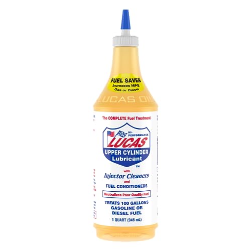
- The world’s #1 fuel additive for both gasoline and diesel...
- A great tune-up in a bottle – treats gasoline, diesel fuel...
- Cleans and lubricates the fuel system, including fuel...
- Improves fuel economy by burning excess exhaust emissions
- Increases power and acceleration by improving fuel flow and...
If the PDF is very large, it may not load in the preview below.
Some older TSBs had multiple PDFs — visit the NHTSA Website to view all PDFs.
If the TSB PDF does not show, download or view it on the NHTSA Website.
Click on the (+) Plus Sign
Then Click on Associated Document(s)
Search NHTSA Database for Recalls
Search NHTSA Database for Vehicle Investigations
View Latest Vehicle Investigations
Search NHTSA Database for Vehicle Complaints
View Latest Vehicle Complaints
TSB/Document ID: WRD-20R
Replacement Service Bulletin Number:
MFR Communication Date: 2021-08-27
MFR Internal Campaign ID/Software Version:
Communication Type: Service Bulletin/Repair Instructions
NHTSA Components: FUEL SYSTEM, GASOLINE
MFR Component System:
MFR Component Subsystem:
Previous TSB | Next TSB |

- [Notice] When you receive a used device, it may be a customer return resold by Amazon without inspection. You can exchange it for a new one through Amazon. As this situation is unavoidable, we sincerely apologize. For any issues, contacting us via Amazon's "Messages" is the best way. THINKSCAN 689BT Bidirectional Scan Tool Can Be Used Immediately After It is Turned On, Without Complicated Registration Process, Which is More Convenient & Quick.
- Full Bi-Directional Control & 3000+ Active Tests: Take control and test components like actuators, fuel injectors, relays, and cooling fans in real time. You’ll quickly see if the problem is in the part itself or the control module — saving you hours of guesswork and frustrating trial-and-error.
- Advanced ECU Coding Capabilities: Handle module matching and hidden feature activation with confidence. When you replace an ECU or want to customize settings, this obd2 scanner diagnostic bi directional tool gives you the professional-level capabilities you need without the dealership price tag.
- 34+ Useful Reset and Maintenance Functions: Complete everyday service tasks smoothly with a wide range of helpful reset and maintenance functions. Whether you’re keeping up with regular upkeep or tackling a specific job, this scanner makes maintenance simpler and less stressful for both DIYers and pros.
- Comprehensive Full System Diagnostics: Diagnose every major system — Engine, Transmission, ABS, SRS, TPMS, and more — all in one place. Finally stop wondering if you’re missing something important; get the full picture and clear codes with ease.

- Top Reasons to Choose the D7S OBD2 Scanner: XTOOL D7S car scan tool, an upgrade of XTOOL D7, offers comprehensive features for automotive technicians, workshops, and DIY enthusiasts 1. Upgraded Hardware: 2+64GB memory, rear camera, intuitive interface, foldable bracket 2. Complete Diagnostics: FCA
 Autoauth, OE-level all system scan, 39+ maintenance services, 4K+ bidirectional, CANFD/DoIP protocol 3. Advanced Capabilities: ECU c0ding, PMI functions 4. Wide Compatibility: Support 10,000+ models, covering 99% vehicle brands 5. Multi-language: Available in 22+ languages, No IP Restrictions 6. 3-Year Updates: Save 300 bucks on software updates for the latest features and optimizations
 - 2026 Upgraded D7S Car Scanner Features: The newly 2026 D7S V2.0 scanner for car brings exciting features for advanced vehicle diagnostics and enhanced user experience 1. FCA AutoAuth: Now supports FCA SGW module for Chrysler, for Jeep, for Dodge (2018+), for Fiat (2017+), enabling faster vehicle communication without gateway restrictions 2. PMI (Offline ECU Pr0gramming): Allows for Ford, for Lincoln, and for Mazda ECU pr0gramming for new modules 3. Optimized Diagnostic Report 2.0: Personalized reports with logos and customer info for auto shops. Note: Compatibility varies by cars, please check before order
- 39+ Services/Resets/Adaptations/Relearns/Calibrations: XTOOL D7S full system car scanner diagnostic tool tackles 99% of common car issues through its 36+ special functions, including Oil Reset, EPB, SAS, BMS, Throttle Reset, Injector C0ding, ABS Bleed, TPMS Reset, Power Balance, etc and also covers specific-vehicle functions like Crank Sensor Relearn, ABS Initialization, Cylinder Power Balance, Fuel Trim Reset, Idle Relearn etc. This car diagnostic scanner enhances efficiency, making repairs and maintenance hassle-free. Tip: DO NOT for All vehicles, please check compatibility first
- Cost-effective ECU C0ding Scan Tool for Specific Brands: Enhance your vehicle's performance with XTOOL D7S! This obd2 scanner all systems bidirectional offers advanced capabilities at an affordable price, supports online for BMW, for Benz and offline for BENZ, for MIT, along with PMI functions for Ford, for Mazda, and for Lincoln. Ideal for technicians and DIY enthusiasts, this automotive scanner diagnostic tool optimizes vehicle performance and enhances the driving experience. Note: Not for all cars and modules, please send car VIN to check the compatibility before purchase
- OE All System Diagnostic & 8 Pids Graphing: XTOOL D7S is a comprehensive all system bi directional obd2 scanner that delivers dealer-level diagnostics, completely controlling over your vehicle’s performance and health. This automotive scan tool can read and clear DTCs, view live data and ECU information, retrieve freeze frames, and perform active tests and full obd2 functions. This bi-directional scan tool can can identify your vehicle's make, model, and year information with just one click and show up to 8 PIDs live data with options for CSV viewing, playback, and recording for in-depth analysis. It is easy-to-use for both professionals and beginners, helping pinpoint issues efficiently

- 【✅Compared to BOSSCOMM IF742, IF745 Offers Full-System Diagnostics】The BOSSCOMM IF745 car diagnostic scanner is an upgraded model of IF742. In addition to supporting all OBD2 Code Reader functions and 6 reset options (ABS/EPB/SAS/BMS/Oil/Throttle), it expands diagnostics from 4 systems (Check Engine/ABS/SRS/Transmission) to vehicle All systems, including Steering, Suspension, and Body Electronics. This provides deeper, more comprehensive diagnostic capabilities.
- 【✨10 OBD2 Functions】The BOSSCOMM IF745 scan tool’s DTC Lookup instantly translates fault codes into user-friendly explanations, its I/M Readiness feature streamlines emissions testing with a single tap, and Freeze Frame lets you pinpoint the exact moment of a fault for in-depth root-cause diagnosis. Combined with a live data dashboard and advanced diagnostics (O2S, OBMon, EVAP), it delivers comprehensive insights for confident troubleshooting.
- 【✨Deep Diagnostics for All Vehicle System Modules】Beyond code reading/clearing and ECU information retrieval, our all-in-one data stream feature lets you inspect all current fault codes and their locations across the vehicle’s systems. This vehicle code reader helps you turn off dashboard warning lights and perform a comprehensive self-check of your car at home—no more back-and-forth trips to the repair shop or hefty inspection fees.
- 【✨6 Essential Resets: ABS Bleeding, Oil, EPB, SAS, Throttle, BMS】The BOSSCOMM IF745 obd2 scanner diagnostic tool swiftly purges air from brake lines to restore braking sensitivity, fine-tunes maintenance cycles to eliminate false alerts, resolves parking brake issues with one-click control, recalibrates steering sensors for stability, optimizes engine idling/acceleration for smoother performance, and deeply resets battery systems to extend lifespan and range via precise parameter adjustments.❗NOTE: Does NOT support bidirectional control, coding, or programming.
- 【✨10,000+ Car Models, AutoVIN, 13 Languages】The BOSSCOMM IF745 vehicle scanner diagnostic tool covers 73+ global car brands and offers support in 13 languages, making it perfect for DIYers, auto mechanics, or as a thoughtful gift. With a single-click AutoVIN feature, it instantly retrieves vehicle serial numbers, streamlining diagnostics for users globally. This adaptable tool balances user-friendliness with precision, catering to both personal and professional requirements.✅Unsure about compatibility? Compatibility will vary on vehicles' model and year, pls reach us via 📧 [email protected] 📧 before purchase.
This product presentation was made with AAWP plugin.