
NHTSA ID Number: 10173212
Manufacturer Communication Number: 34-085
TSB/Document Date: 2020-04-03
Summary
Information Only – Vehicles may have the connector seals on the wheel speed sensor incorrectly installed, which may lead to water intrusion and corrosion in some vehicles.
REPAIR PROCEDURE
ABS Wheel Speed Sensor Water Intrusion
34-085
ABS Harness R&R Procedure
1. Disconnect the ABS Harness connector from the firewall (Figure 1). Cut all cable ties that secure the harness
under the cab until it splits between the front and rear sections of the harness. This location is usually under
the cab, just rearward of where the harness crosses over the frame rail.
Figure 1
2. Find the harness at the furthest point from the cab and begin removing it. The furthest point is usually the rear
wheel speed sensor on the RH side forward drive axle.
3. Carefully unplug all connectors on the ABS harness and cut all cable ties securing the ABS harness from the
RH side forward drive axle toward the rear of the truck. Continue around the back of the truck and up the LH
frame rail to the cab.
4. When the harness is removed past the back of cab crossmember, move to the front half of the harness. Start
at the right front wheel and continue rearward to the back of cab crossmember. Completely remove the harness
from the chassis.
5. Reinstallation in reverse order of removal. The new harness can be secured to the bottom of the harness
bundle and can be routed under crossmembers instead of through the gussets. Add protective nylon wrap
where the harness comes into contact with the bottom of the crossmember.
6. Route the harness to avoid sharp edges and moving parts. Any portions of the harness that were covered with
protective wrap need to be re-wrapped.
2/13/2020
34-085
Page 1 of 1
SD-13-4860
Bendix® WS-24™ Antilock Wheel Speed Sensor
Various Bendix® WS-24™ Wheel Speed Sensors
WS-24 Speed Sensors with Trade Dress
90° Angle
Bendix® WS-24™
Sensor
Straight
WS-24 Sensor
90° Angle
WS-24 Sensor
Straight
WS-24 Sensor
The appearance of the WS-24 wheel speed sensors
may vary depending upon the date and location of
manufacture, but they are interchangeable provided
they are the same type, e.g., straight or 90°.
Connectors
Packard®
GT 150
Series
Packard
Metripack
150.2 Series
Deutsch®
DTM06
Series
Packard
Metripack 280
Series (female)
Packard
Metripack 280
Series (male)
Deutsch
DT04 Series
Standard
Round
2-Pin
Figure 1 – Wheel Speed Sensors and Connectors
DESCRIPTION
The Bendix ® WS -24™ wheel speed sensor is an
electromagnetic device used to obtain vehicle speed
information for an antilock controller. When the wheel
rotates, the sensor and an exciter ring (sometimes called a
“rotor” or “tone” wheel) generate a simple AC signal. This
signal is sent to the controller, which analyzes the data and
commands the antilock system accordingly.
Specifically, the speed sensor consists of a coil, pole piece,
and a magnet. The exciter is a steel ring or gear-like device
Exciter Ring
Mounting Block
Wheel
Speed
Sensor
Figure 2 – Wheel End ABS Components
1
GENERAL SAFETY GUIDELINES
WARNING! PLEASE READ AND
FOLLOW THESE INSTRUCTIONS
TO AVOID PERSONAL INJURY OR DEATH:
When working on or around a vehicle, the following
guidelines should be observed AT ALL TIMES:
▲Park the vehicle on a level surface, apply the parking
brakes and always block the wheels. Always wear personal
protection equipment.
▲Stop the engine and remove the ignition key when working
under or around the vehicle. When working in the engine
compartment, the engine should be shut off and the ignition
key should be removed. Where circumstances require that
the engine be in operation, EXTREME CAUTION should be
used to prevent personal injury resulting from contact with
moving, rotating, leaking, heated or electrically-charged
components.
▲Do not attempt to install, remove, disassemble or
assemble a component until you have read, and thoroughly
understand, the recommended procedures. Use only the
proper tools and observe all precautions pertaining to use
of those tools.
▲If the work is being performed on the vehicle’s air brake
system, or any auxiliary pressurized air systems, make
certain to drain the air pressure from all reservoirs before
beginning ANY work on the vehicle. If the vehicle is
equipped with a Bendix® AD-IS® air dryer system, a Bendix ®
®
DRM™ dryer reservoir module, or a Bendix ® AD-9si ® air
dryer, be sure to drain the purge reservoir.
▲Following the vehicle manufacturer’s recommended
procedures, deactivate the electrical system in a manner
that safely removes all electrical power from the vehicle.
▲Never exceed manufacturer’s recommended pressures.
▲Never connect or disconnect a hose or line containing
pressure; it may whip and/or cause hazardous airborne
dust and dirt particles. Wear eye protection. Slowly open
connections with care, and verify that no pressure is
present. Never remove a component or plug unless you are
certain all system pressure has been depleted.
▲Use only genuine Bendix ® brand replacement parts,
components and kits. Replacement hardware, tubing, hose,
fittings, wiring, etc. must be of equivalent size, type and
strength as original equipment and be designed specifically
for such applications and systems.
▲Components with stripped threads or damaged parts should
be replaced rather than repaired. Do not attempt repairs
requiring machining or welding unless specifically stated
and approved by the vehicle and component manufacturer.
▲Prior to returning the vehicle to service, make certain all
components and systems are restored to their proper
operating condition.
▲For vehicles with Automatic Traction Control (ATC), the ATC
function must be disabled (ATC indicator lamp should be
ON) prior to performing any vehicle maintenance where
one or more wheels on a drive axle are lifted off the ground
and moving.
▲The power MUST be temporarily disconnected from the
radar sensor whenever any tests USING A DYNAMOMETER
are conducted on a vehicle equipped with a Bendix ®
Wingman ® system.
▲You should consult the vehicle manufacturer's operating
and service manuals, and any related literature, in
conjunction with the Guidelines above.
2
WARNING: Not all wheels and valve stems are
compatible with Bendix® Air Disc Brakes. Use only
wheels and valve stems approved by the vehicle
manufacturer to avoid the risk of valve stem shear
and other compatibility issues.
WARNING: AVOID CREATING
DUST. POSSIBLE CANCER AND LUNG
DISEASE HAZARD.
While Bendix Spicer Foundation Brake LLC does
not offer asbestos brake linings, the long-term
affects of some non-asbestos fibers have not been
determined. Current Occupational Safety and Health
Administration (OSHA) Regulations cover exposure
levels to some components of non-asbestos linings,
but not all. The following precautions must be used
when handling these materials.
Avoid creating dust. Compressed air or dry brushing
must never be used for cleaning brake assemblies
or the work area.
▲ Bendix recommends that workers doing brake
work must take steps to minimize exposure
to airborne brake lining particles. Proper
procedures to reduce exposure include working
in a well-ventilated area, segregation of areas
where brake work is done, use of local filtered
ventilation systems or use of enclosed cells with
filtered vacuums. Respirators approved by the
Mine Safety and Health Administration (MSHA)
or National Institute for Occupational Safety
and Health (NIOSH) should be worn at all times
during brake servicing.
▲ Workers must wash before eating, drinking, or
smoking; shower after working, and should not
wear work clothes home. Work clothes should
be vacuumed and laundered separately without
shaking.
▲ OSHA & EPA Regulations regarding testing,
disposal of waste, and methods of reducing
exposure for asbestos are set forth in 29 &
40 Code of Federal Regulations §1910.1001 &
61.150, respectively. These Regulations provide
valuable information which can be utilized to
reduce exposure to airborne particles.
▲ Safety Data Sheets on this product, as required
by OSHA, are available from Bendix. Call
1-800-247-2725 and speak to the Tech Team or
e-mail techteam@bendix.com.
that has regularly spaced high and low spots called “teeth.”
The sensor is mounted in a fixed position, while the exciter
is installed on a rotating member so that its “teeth” move,
in close proximity, past the tip of the sensor.
The Bendix® WS-24™ sensor is available in both straight and
90° versions, to accommodate axle/wheel space limitations.
(See Figure 1.)
OPERATION
TECHNICAL INFORMATION
The sensor’s magnet and pole piece form a magnetic field.
As the exciter ring passes by the sensor, the magnetic field
is altered, which generates AC voltage in the sensor coil.
Each time an exciter tooth and its adjacent space move past
the tip of the sensor, an AC voltage “cycle” is generated.
Electrical connector - 2 Pin
The number of AC cycles per revolution of the vehicle’s
wheel depends on the number of teeth in the exciter ring,
which is programmed into the antilock controller. Using
the programmed data, the controller can calculate “vehicle
speed” by analyzing the frequency of AC cycles sent by
the speed sensor. (The frequency of AC cycles is directly
proportional to wheel speed.) See Figure 4.
Sensor body outer diameter - 0.627 inch
AC voltage is also proportional to speed, but voltage is not
used to determine speed. It is only an indication of AC signal
strength. The amount of AC voltage generated by a specific
speed sensor depends on the distance, or “gap” between
the tip of the sensor and the surface of the exciter. Voltage
increases as the sensor gap decreases.
Typically, the Bendix® WS-24™ wheel speed sensor is
installed in mounting blocks that are welded to the axle
housing. (See Figure 2.) The WS-24 wheel speed sensors
are protected by a stainless steel sheath. The sensors are
designed to be used with beryllium copper or stainless steel
clamping sleeves (sometimes referred to as a “retainer
bushing”, “friction sleeve” or “clip”) (See Figure 3). The
clamping sleeve provides a friction fit between the mounting
block bore and the WS-24 wheel speed sensor.
Sensor resistance (-40°C - 220°C) 1100 - 3400 ohms
Output voltage - At a minimum of 100 Hz (approximately
7 mph) at a gap of .028 inches should produce a sensor
voltage of 0.350 VAC
Sensor resistance (20°C) 1575 - 2100 ohms
Note: Previous model Bendix® WS-20™ sensor’s normal
resistance range across pins at room temperature was
rated at 2000 - 5000 ohms.
The friction fit allows the WS-24 sensor to “slide” back and
forth under force but to retain its position when the force is
removed.
When the WS-24 sensor is inserted all the way into the
mounting block and the wheel is installed on the axle, the
hub exciter contacts the sensor, which pushes the sensor
back. Also, normal bearing play will “bump” the sensor away
from the exciter. The combination of these two actions will
establish a running clearance or air gap between the sensor
and the exciter.
Peak to Peak
Low Speed
Note that Bendix® sleeve part number 5006849 can not be
used with the WS-24 wheel speed sensors. Always use
the correct clamping sleeves to avoid problems associated
with reduced retention force, such as unwanted sensor
movement and resulting ABS trouble codes.
Peak to Peak
High Speed
Figure 4 – Speed Sensor Voltage Cycle Output
Beryllium Copper Clamping Sleeves
Part No. 5006849
(Do not use with
Bendix® WS-24™
Sensors)
“BW” in a
diamond
Stainless Steel Clamping Sleeve
Part No.
5012878
“BX” in a
swoosh
symbol
Part No.
K152407
Knorr-Bremse
Logo
Swoosh
Symbol
Figure 3 – Clamping Sleeves
3
PREVENTIVE MAINTENANCE
1. Every 3 months; 25,000 miles; 900 operating hours; or
during the vehicle chassis lubrication interval, make the
visual inspections noted in “SERVICE CHECKS” below.
2. Every 12 months; 100,000 miles; or 3600 operating
hours, perform the OPERATIONAL TEST in this manual.
SERVICE CHECKS
Check all wiring and connectors. Make sure connections
are free from visible damage.
Antilock Controller &
Relay
Examine the sensor. Make sure the sensor, mounting
bracket, and foundation brake components are not
damaged. Repair/replace as necessary.
SENSOR IDENTIFICATION
Use Bendix® ACom® diagnostic software to identify the
suspected sensor. To verify the correct wheel sensor or axle
has been identified, the ACom software can be used to view
real time wheel speed sensor outputs. To determine which
axle has been identified as drive or additional, lift the axle in
question and hand spin the wheel at least ½ revolution per
second. The wheel speed will be displayed via the ACom
software.
INSPECT FOR PHYSICAL DAMAGE
Inspect the sensor cable for cuts, evidence of pinching
or wear, or abrasions with wiring exposed. Make sure the
block is securely attached to the axle housing. If any of
the above conditions are noted, replace the sensor and
clamping sleeve, then clear the Diagnostic Trouble Code
(DTC) according to the Electronic Control Unit (ECU) Service
Data sheet directions. Re-check the system before returning
the vehicle to service.
ELECTRICAL TESTING
The vehicle should be at an ambient temperature to achieve
a nominal resistance, or AC voltage, value. Be observant
of the wheel end temperature when taking measurement
readings. At extreme temperature ranges, -40°F to 428°F
(-40° to 220°C), the sensor resistance can vary from 1100
to 3400 ohms. To avoid possible connector seal damage
it is recommended to first check sensor resistance, or AC
voltage output, at the ECU connections. If the resistance
or voltage output is not within the stated parameters at this
location, perform the test at the next connector, typically the
wheel end. Before disconnecting any electrical connections
at the wheel end, remove as much contamination from the
connector as possible to preserve the sealing integrity of
the connection.
1. Inspect the connectors and terminals for corrosion,
physical damage (bent) or loose connections. If possible,
repair and/or clean the connector and terminals.
4
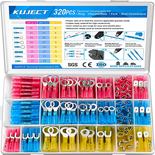
- Multiple Choices: Proper ratio of various types to meet the...
- Stronghold and Durability: We adopt premium copper core to...
- Waterproof: With the adhesive melted when heated, the heat...
- Straightforward Visual Inspection: Translucent...
- Wide Applications: Good electrical conductivity and water...
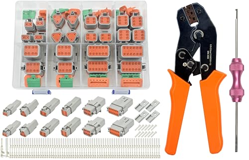
- 🔧217PCS Deutsch DT Connector Kit with Professional Tools...
- ⚡Premium Ratcheting Crimper Tool - Features self-adjusting...
- 🛡️IP68 Waterproof & Heavy-Duty Construction - Made of...
- ✔️High-Conductivity Stamped Terminals - 75 pairs of...
- 🚗Universal Vehicle Compatibility & Warranty - Perfect fit...
If the PDF is very large, it may not load in the preview below.
Some older TSBs had multiple PDFs — visit the NHTSA Website to view all PDFs.
If the TSB PDF does not show, download or view it on the NHTSA Website.
Click on the (+) Plus Sign
Then Click on Associated Document(s)
Search NHTSA Database for Recalls
Search NHTSA Database for Vehicle Investigations
View Latest Vehicle Investigations
Search NHTSA Database for Vehicle Complaints
View Latest Vehicle Complaints
TSB/Document ID: 34-085
Replacement Service Bulletin Number:
MFR Communication Date: 2020-03-03
MFR Internal Campaign ID/Software Version:
Communication Type: Service Bulletin/Repair Instructions
NHTSA Components: ELECTRICAL SYSTEM
MFR Component System:
MFR Component Subsystem:
Previous TSB | Next TSB |

- [Notice] When you receive a used device, it may be a customer return resold by Amazon without inspection. You can exchange it for a new one through Amazon. As this situation is unavoidable, we sincerely apologize. For any issues, contacting us via Amazon's "Messages" is the best way. THINKSCAN 689BT Bidirectional Scan Tool Can Be Used Immediately After It is Turned On, Without Complicated Registration Process, Which is More Convenient & Quick.
- Full Bi-Directional Control & 3000+ Active Tests: Take control and test components like actuators, fuel injectors, relays, and cooling fans in real time. You’ll quickly see if the problem is in the part itself or the control module — saving you hours of guesswork and frustrating trial-and-error.
- Advanced ECU Coding Capabilities: Handle module matching and hidden feature activation with confidence. When you replace an ECU or want to customize settings, this obd2 scanner diagnostic bi directional tool gives you the professional-level capabilities you need without the dealership price tag.
- 34+ Useful Reset and Maintenance Functions: Complete everyday service tasks smoothly with a wide range of helpful reset and maintenance functions. Whether you’re keeping up with regular upkeep or tackling a specific job, this scanner makes maintenance simpler and less stressful for both DIYers and pros.
- Comprehensive Full System Diagnostics: Diagnose every major system — Engine, Transmission
 , ABS, SRS, TPMS, and more — all in one place. Finally stop wondering if you’re missing something important; get the full picture and clear codes with ease.

- Top Reasons to Choose the D7S OBD2 Scanner: XTOOL D7S car scan tool, an upgrade of XTOOL D7, offers comprehensive features for automotive technicians, workshops, and DIY enthusiasts 1. Upgraded Hardware: 2+64GB memory, rear camera, intuitive interface, foldable bracket 2. Complete Diagnostics: FCA Autoauth, OE-level all system scan, 39+ maintenance services, 4K+ bidirectional, CANFD/DoIP protocol 3. Advanced Capabilities: ECU coding, PMI functions 4. Wide Compatibility: Support 10,000+ models, covering 99% vehicle brands 5. Multi-language: Available in 22+ languages, No IP Restrictions 6. 3-Year Updates: Save 300 bucks on software updates for the latest features and optimizations
- 2026 Upgraded D7S Car Scanner Features: The newly 2026 D7S V2.0 scanner for car brings exciting features for advanced vehicle diagnostics and enhanced user experience 1. FCA AutoAuth: Now supports FCA SGW module for Chrysler, for Jeep, for Dodge (2018+), for Fiat (2017+), enabling faster vehicle communication without gateway restrictions 2. PMI (Offline ECU Programming): Allows for Ford, for Lincoln, and for Mazda ECU programming for new modules 3. Optimized Diagnostic Report 2.0: Personalized reports with logos and customer info for auto shops. Note: Compatibility varies by cars, please check before order
- Cost-effective ECU Coding Scan Tool for Specific Brands: Enhance your vehicle's performance with XTOOL D7S! This obd2 scanner all systems bidirectional offers advanced capabilities at an affordable price, supports online for BMW, for Benz and offline for BENZ, for MIT, along with PMI functions for Ford, for Mazda, and for Lincoln. Ideal for technicians and DIY enthusiasts, this automotive scanner diagnostic tool optimizes vehicle performance and enhances the driving experience. Note: Not for all cars and modules, please send car VIN to check the compatibility before purchase
- OE All System Diagnostic & 8 Pids Graphing: XTOOL D7S is a comprehensive all system bi directional obd2 scanner that delivers dealer-level diagnostics, completely controlling over your vehicle’s performance and health. This automotive scan tool can read and clear DTCs, view live data and ECU information, retrieve freeze frames, and perform active tests and full obd2 functions. This bi-directional scan tool can can identify your vehicle's make, model, and year information with just one click and show up to 8 PIDs live data with options for CSV viewing, playback, and recording for in-depth analysis. It is easy-to-use for both professionals and beginners, helping pinpoint issues efficiently
- 3 Years Software Update, Value for Money: With 3 years of software updates and 22+ languages(no IP restrictions), XTOOL D7S auto scanner code scanner ensures ongoing compatibility for the latest car models and improved diagnostic functions. This all system vehicle diagnostic scanner comes with a 30-day return policy and a 24-month repair for dependable performance. XTOOL are dedicated to your satisfaction, so enjoy seamless support and lifetime expert assistance. Should you encounter any issues or concerns, don’t hesitate to reach out XTOOL. D7S with newest update with 22 languages freely transfer without authorization, check details from setting-language or from XTOOL

- 【✅Compared to BOSSCOMM IF742, IF745 Offers Full-System Diagnostics】The BOSSCOMM IF745 car diagnostic scanner is an upgraded model of IF742. In addition to supporting all OBD2 Code Reader functions and 6 reset options (ABS/EPB/SAS/BMS/Oil/Throttle), it expands diagnostics from 4 systems (Check Engine/ABS/SRS/Transmission) to vehicle All systems, including Steering, Suspension, and Body Electronics. This provides deeper, more comprehensive diagnostic capabilities.
- 【✨6 Essential Resets: ABS Bleeding, Oil, EPB, SAS, Throttle, BMS】The BOSSCOMM IF745 obd2 scanner diagnostic tool swiftly purges air from brake lines to restore braking sensitivity, fine-tunes maintenance cycles to eliminate false alerts, resolves parking brake issues with one-click control, recalibrates steering sensors for stability, optimizes engine idling/acceleration for smoother performance, and deeply resets battery systems to extend lifespan and range via precise parameter adjustments.❗NOTE: Does NOT support bidirectional control, coding, or programming.
- 【✨Deep Diagnostics for All Vehicle System Modules】Beyond code reading/clearing and ECU information retrieval, our all-in-one data stream feature lets you inspect all current fault codes and their locations across the vehicle’s systems. This vehicle code reader helps you turn off dashboard warning lights and perform a comprehensive self-check of your car at home—no more back-and-forth trips to the repair shop or hefty inspection fees.
- 【✨10 OBD2 Functions】The BOSSCOMM IF745 scan tool’s DTC Lookup instantly translates fault codes into user-friendly explanations, its I/M Readiness feature streamlines emissions testing with a single tap, and Freeze Frame lets you pinpoint the exact moment of a fault for in-depth root-cause diagnosis. Combined with a live data dashboard and advanced diagnostics (O2S, OBMon, EVAP), it delivers comprehensive insights for confident troubleshooting.
- 【✨10,000+ Car Models, AutoVIN, 13 Languages】The BOSSCOMM IF745 vehicle scanner diagnostic tool covers 73+ global car brands and offers support in 13 languages, making it perfect for DIYers, auto mechanics, or as a thoughtful gift. With a single-click AutoVIN feature, it instantly retrieves vehicle serial numbers, streamlining diagnostics for users globally. This adaptable tool balances user-friendliness with precision, catering to both personal and professional requirements.✅Unsure about compatibility? Compatibility will vary on vehicles' model and year, pls reach us via 📧 [email protected] 📧 before purchase.
This product presentation was made with AAWP plugin.