
NHTSA ID Number: 10115971
Manufacturer Communication Number: FS-2016-06
TSB/Document Date: 2017-08-25
Summary
Gillig has received reports of partial cracking in the steering gear mounting plate in some Low Floor buses. We are now requesting that owners of all Low Floor buses from model year 1997 through June, 2015 inspect the steering gear mounting plates per the instructions in this bulletin. Inspections should commence at the next Preventative Maintenance Cycle and continue at every 12,000 mile PM inspection thereafter. Steering Gear Mounting Plates found to have cracks less than 6 inches in length should be changed out at the earliest opportunity. Any bus found to have a Steering Gear Mounting Plate with a crack 6 inches long or longer must be immediately removed from service and the Plate replaced before reentering service. In either instance, Gillig will reimburse owners the cost of any replacement plate and the labor required to perform the repair. Lower floor
Number:
FS-2016-06
Date:__December 20, 2016
Model:
29', 35' & 40' Low Floor Buses
Model Years:
1997 - 2016
Subject:
Approved:
Robert L. Birdwell, Executive Director
Quality Control & Field Service
Inspection Of Steering Gear Mounting Plate
Gillig has received reports of partial cracking in the steering gear mounting plate in some
Low Floor buses. This plate is a structural member that supports the steering gear and is
located under the driver’s area, inboard of the battery box.
FIELD
SERVICE
BULLETIN
Gillig is now requesting that, as part of the standard required inspection of the steering
system components outlined in the Service Manual, customers specifically inspect the steering
gear mounting plate as outlined in this bulletin, beginning with the vehicle’s next preventative
maintenance inspection.
Gillig wishes to assure you that there have been no reported failures of the plate in
service, nor any injuries, deaths or loss of vehicle control related to this issue. Rather, the
partial cracks form and grow very slowly and are easy to detect with visual inspections.
You should inspect the steering gear mounting plates in all Low Floor buses from model
year 1997 through June, 2015 per the instructions in this bulletin. Inspections should
commence at the next Preventative Maintenance Cycle and continue at every 12,000 mile PM
inspection thereafter.
p
Steering Gear Mounting Plates found to have cracks less than 6 inches in length
should be changed out at the earliest opportunity.
p
Any bus found to have a Steering Gear Mounting Plate with a crack 6 inches long or
longer must be immediately removed from service and the Steering Gear Mounting
Plate replaced before reentering service.
p
In either event, Gillig will reimburse you for the cost of any replacement plate and
the labor required to perform the repair.
RLB:rlb
Gillig, LLC
25800 Clawiter Road
Hayward, CA 94545
(800) 735-1500
(510) 785-1500
[email protected]
FSB-2016-06
Page 2
You should replace any cracked Steering Gear Mounting Plate in accordance with the
instructions in this Field Service Bulletin.
Upon removal, all cracked plates should be marked with the vehicle identification number,
vehicle mileage, and the date that the Steering Gear Mounting Plate was removed from the
vehicle. You should then preserve and store the plate until it can be reviewed by Gillig Field
Service personnel.
Any vehicle lessor receiving this notice should forward a copy of this bulletin to the
lessee within 10 days.
If you have already performed this repair, you may be eligible to receive reimbursement for
the cost of performing the repair. For more information, contact Gillig Field Service at 800-7351500.
If you need Steering Gear Mounting Plates, please order from “[email protected]”,
(VIN & Miles needed). The Steering Gear Mounting Plates and all hardware will be provided at no
cost to you.
FIELD
SERVICE
BULLETIN
After the repair is completed, you can file for labor reimbursement through the normal
warranty process. If you need assistance with filing a claim, you can contact Gillig Warranty at
“[email protected]”. Gillig estimates the SRT for the repair is 6 hours.
RLB:rlb
Gillig, LLC
25800 Clawiter Road
Hayward, CA 94545
(800) 735-1500
(510) 785-1500
BB@Gillig.com
FSB-2016-06
Page 3
GILLIG Low Floor Steering Gear Plate Inspection Procedures
Notes
Access to the underside of the bus is required for part of this procedure. Therefore, the use of a
bus lift or service pit is required.
The bus shall be turned off, parking brakes applied, and the Battery Disconnect switched to the
OFF position.
Localized cleaning of the Steering Gear Plate may be necessary for proper inspection. Use a
suitable cleaner/degreaser to clean plate in the inspection areas, if required.
Tools Required:
1. Flashlight
2. Inspection Mirror
Inspection Interval
Inspection of the Steering Gear Mounting Plate is required at every 12,000 mile maintenance
period.
FIELD
SERVICE
BULLETIN
Location and Terminology of Steering Gear and Steering Gear Mounting Plate
The steering gear is mounted behind the battery box, which is accessed through the forward-most
streetside skirt panel on the bus.
The Steering Gear Mounting Plate has two sides: gear side and washer side. The following detail
defines the gear and washer sides.
Terminology of Steering Gear Mounting Plate
FSB-2016-06
Page 4
Access to the Steering Gear Plate
Each side of the Steering Gear Mounting Plate requires access from different entry points:
p
Gear side access is through the battery box.
p
Washer side access is from the underside of the bus.
Access to the gear side of the steering gear mounting plate is through the battery box. For
inspection purposes, the top shelf of the battery box is required to be unlocked and slid out.
Located at the back of the battery box is a cutout which gives access to the steering gear and the
gear side of the steering gear mounting plate.
FIELD
SERVICE
BULLETIN
Access to the washer side of the steering gear mounting plate is from the underside of the bus.
The use of a bus lift or pit is required for inspecting this side of the steering gear mounting plate.
FSB-2016-06
Page 5
Gear Side Steering Gear Plate Inspection
After pulling the top tray of the battery box out, inspect the steering gear plate where the steering
gear bolts to the plate. If required, utilize a flashlight to aid in the inspection of this area. Cracks, if
any, should be located at the areas shown in the picture below.
Washer Side Steering Gear Plate Inspection
FIELD
SERVICE
BULLETIN
After gaining access to the underside of the steering gear area of the bus, locate the Pitman Arm
on the backside of the Steering Gear. Inspect the two sets of mounting bolts adjacent to the
Pitman Arm which mount the Steering Gear to the Steering Gear Plate. An inspection mirror and
flashlight may aid in this inspection. Look for cracks in the immediate area of the bolt locations.
FSB-2016-06
Page 6
Typical Crack Location and Orientation
Cracks, if present, should initiate near the steering gear mounting holes in the plate and propagate
towards the top and bottom of the plate.
FIELD
SERVICE
BULLETIN
Crack Identification Detail
Action
p
Steering gear plates found with cracks less than 6” in length should be changed out at
the earliest opportunity.
p
Any bus with a plate found to have with a crack 6” or longer must be immediately
removed from service and the plate replaced before reentering service.
p
Any plate removed must be marked with the vehicle identification number, the vehicle
mileage and the date that the plate was removed from vehicle. The plate should then
be stored until it can be reviewed by Gillig Field Service personnel.
FSB-2016-06
Page 7
GILLIG Low Floor Bus
Steering Gear Mounting Plate Replacement Procedure
Overview Instructions
1. This procedure covers the replacement of the existing 3/8” thick steering gear
mounting plate with a 3/4” thick mounting plate on all GILLIG Low Floor Buses.
2. A vehicle lift or pit is required to complete this procedure.
3. Refer to your GILLIG Service Manual for any procedures not covered in this
document.
4. Always reinstall the same steering gear that was removed, unless the gear needs
to be replaced.
5. Do not make any adjustments to the axle stop bolts during this procedure. If any
adjustments are made, the steering gear poppets may require possible readjustment per TRW Service Bulletin # TAS-101.
FIELD
SERVICE
BULLETIN
Special Tools & Materials Required
1. Torque wrench(s)
A. Min Torque Required is 90 ft-lbs.
B. Max Torque Required is 445 ft-lbs. (with Anti Seize)
2. Lifting fixture for the Steering Gear and Plate
3. Pullers and wedge tools to remove pitman arm and draglink
4. Hose caps or plugs for sealing disconnected hydraulic fittings
#8, #10, and #12 Fittings
5. Bostik Never-Seez Anti-Seize, Regular Grade (K=.13)
6. 3/4-in drive breaker bar
7. 4-6 ft ladder if using a lift
8. Pry bar
FSB-2016-06
Page 8
Parts Required
Application
Part Number
29ft Stainless Steel
Low Floor w/ Drum 05-74397-000
Brakes
Description
Plate, Steering Gear
Mounting, 29 SSLF
QTY Replaces P/N
1
05-63059-000 or
05-50256-000
1
05-63058-000
1
05-50265-000
1
05-63058-000 or
05-45365-000
1
05-36841-000
1
N/A
-OR29ft Stainless Steel
Low Floor w/ Disc 05-74344-000
Brakes
Plate, Steering Gear
Mounting, 76000 LF
-OR-
29ft Carbon Steel
Low Floor w/ Raised 05-74685-000
Gear
Plate, Steering Gear
Mounting, Mild Steel LF,
Raised Gear
-OR-
35 and 40ft
Stainless Steel Low 05-74344-000
Floor
Plate, Steering Gear
Mounting, 76000 LF
FIELD
SERVICE
BULLETIN
-OR-
29, 35, and 40ft
Carbon Steel Low
Floor
05-74636-000
Plate, Steering Gear
Mounting, Mild Steel LF
-AND-
Hardware Kit
(required for all
plate replacements)
54-74537-000
Kit, Hardware, 3/4THK
Steering Gear Plate
Removal of Old Steering Gear Plate
1.
Use the appropriate personal protective equipment for under-bus maintenance and use of
cleaner/de-greaser agents.
2.
Safely place bus on vehicle lift or pit. Place front wheels in straight ahead position. If on a
lift, do not yet lift the bus until Step 3, Battery Removal, is completed.
Ensure parking brakes are applied, engine off, and battery disconnect switch is in the OFF
position.
Disconnect and remove the battery located on the upper battery tray. Start by removing the
negative/chassis ground lead before removing the positive lead. Refer to your GILLIG
Service Manual for additional details for battery removal. Note: It is not necessary to remove
the battery on the lower tray. Removal of the upper battery will allow access to the gear side
of the plate. Always lift the battery with handles or proper lifting devices.
3.
4.
FSB-2016-06
Page 9
5.
6.
7.
8.
9.
10.
11.
12.
13.
14.
15.
16.
If using a lift, raise the bus to a sufficient height to reach the steering gear plate and all plate
mounting bolts.
Thoroughly clean off all outside dirt and grease from the steering gear, especially around the
hose connections, with a suitable cleaner/de-greaser.
Remove the draglink from the pitman arm.
Disconnect the intermediate shaft from the steering gear by loosening the universal joint
pinch bolt and sliding the intermediate shaft free from the steering gear. Do NOT hammer or
pound the universal joint coupling off the steering gear input shaft, as this can cause
damage to the input shaft and/or internal damage to the steering gear.
Disconnect clamp securing the air line adjacent to the steering gear.
Loosen the 5 steering gear mounting bolts shown in Detail B but do not remove the
hardware. Note: it may be necessary to rotate the pitman arm clear of the lower, 7/8” bolt. If
necessary, rotate it just enough to provide clearance to break the bolt loose. Excessive
rotation may require resetting the steering gear poppets.
Place the lifting fixture to hold the steering gear and mounting plate.
Remove the 10 bolts holding the steering gear mounting plate to the bus chassis. Note:
Access is provided to the heads of the steering gear plate mounting bolts through the
battery box where the upper battery was removed. The use of a swivel joint and socket
extensions may be useful. If using a lift, a 4-6 ft ladder can be used to aid in access through
the cut-out in the back of the battery box. A second person should secure the nuts on the
backside of the plate to prevent them from spinning.
Disconnect power steering supply and return hoses at steering gear. Cap both hose ends
and steering gear fittings with plugs to prevent contamination and excessive drainage of
hydraulic fluid. Note: It may be useful to place a bucket or absorbent material under the
steering gear when disconnecting the hydraulic lines for spill containment.
Lower the steering gear and mounting plate assembly from the chassis. Take special
caution to avoid damaging surrounding parts, lines, fittings, or other equipment. In order to
avoid these parts, the steering gear plate may need to be slightly rotated prior to lowering
out of the chassis.
Use a suitable device (forklift, hoist, etc.) to remove the steering gear and plate from the
fixture and place on a workbench or ground.
Remove the Pitman arm from the steering gear. Note: The output shaft and Pitman arm have
alignment marks stamped into them. These may be hard to see, especially if they are
dirty/greasy. If the alignment marks are not easily seen, it may be useful to mark the
alignment with an alternative method, like a paint pen, prior to removal. The Pitman arm will
be reinstalled in the same position at the end of this procedure. See Detail A.
FIELD
SERVICE
BULLETIN
FSB-2016-10
Page 10
Note:
A.
B.
C.
17.
18.
19.
20.
A chisel will help to loosen the pitman arm from the steering output shaft. Use a
puller if you cannot remove the pitman arm by hand.
If using a chisel to spread the pitman arm boss to loosen the pitman arm for removal,
keep a firm grip on the chisel. Failure to do this may result in the chisel flying loose
and causing injury. Never leave the chisel wedged in the pitman arm boss. If you
cannot remove the pitman arm from the shaft with a chisel and your hands, remove
the chisel from the pitman arm and use a puller.
Once the draglink is removed do not allow the input shaft on the steering gear to
rotate more than 1.5 input shaft revolutions from straight ahead position. Rotating the
input shaft more than 1.5 rotations from straight ahead with the draglink removed
could disrupt the poppet setting set at initial installation. The steering gear is in the
straight ahead position when the timing marks on the end of the housing trunnion and
the sector shaft are aligned, as shown in Detail A.
FIELD
SERVICE
BULLETIN
Unbolt the steering gear from the mounting plate.
Clean the steering gear with a rag moistened with a suitable cleaner or de-greaser, then
inspect the steering gear for any signs of wear or damage.
Clean off the mating surfaces of the steering gear to prepare for mounting to the new 3/4”
thick mounting plate.
Remove all existing steering gear plate fasteners from the chassis to mount the plate. These
will be replaced. Note: It may be necessary to remove the clamp securing the coolant/heater
lines for proper access to remove the fasteners.
FSB-2016-10
Page 11
Installation of New Steering Gear Plate
21.
Install the steering gear in reverse order on the new 3/4” thick steering gear mounting plate
using anti-seize on all mounting fasteners. See Detail B for installation details and torque
values. Do not torque mounting fasteners until Step 28, after re-installation of plate into
chassis.
FIELD
SERVICE
BULLETIN
Detail B – Steering Gear Mounting Hardware and Torque
22. Clean off the steering gear output shaft and clean the spline and bolting surfaces on the
Pitman arm. Re-install the pitman arm to the output shaft. Ensure the alignment marks are
properly aligned, as shown in Detail A. Apply anti-seize to the new pinch bolt, install, and
torque to 260-280 ft-lbs. See Detail C for hardware details.
Detail C – Pitman Arm Pinch Bolt Installation
FSB-2016-10
Page 12
23.
Apply anti-seize to new plate mounting bolts, insert loosely into chassis mounting holes,
and reinstall/re-secure coolant lines back into place. See Detail D for installation details.
FIELD
SERVICE
BULLETIN
Detail D – Mounting Plate Hardware and Torque
24.
25.
26.
27.
28.
29.
30.
Mount the new steering gear plate with steering gear into the lifting fixture.
Using the lifting fixture, reinstall the steering gear and plate assembly in the chassis.
Take special caution to avoid damaging surrounding parts, lines, fittings, or other
equipment. In order to avoid these parts, the steering gear plate may need to be slightly
rotated prior to reinstalling into the chassis.
Remove fixture and torque plate mounting bolts (Detail D) to 90 ft-lbs.
Verify all mounting plate mounting bolts are properly torqued and apply torque seal.
Torque steering gear mounting bolts from Step 21 and apply torque seal.
Clean off the draglink ball joint taper and threaded section and clean off the mating taper
in the pitman arm. Re-install the draglink to the Pitman arm and torque the nut to 225
ftlbs. Install a new cotter pin. Anti-Seize is not required at this connection. Note: If
required to align castle nut with cotter pin hole, apply additional torque to castle nut.
PTorque on castle nut not to exceed 400 ft-lbs.
Install the intermediate shaft on the steering gear input shaft. Tighten the pinch bolt to
63-75 ft-lbs. Do NOT apply anti-seize to this pinch bolt. See Detail E.
FSB-2016-10
Page 13
Detail E – Intermediate Shaft Pinch Bolt Installation
31.
32.
Remove hose plugs, clean off the hose connection fittings and the hose ends.
Connect the power steering supply and return hoses to the steering gear. See Detail F.
FIELD
SERVICE
BULLETIN
Detail F – Steering Gear Hydraulic Hoses
33.
34.
35.
36.
37.
38.
39.
40.
41.
Note: If the clamp securing the coolant/heater lines was removed to allow access, secure
the lines with the clamp and reattach to its original location.
Lower the bus if on a lift. Remove lifts from bus.
Reinstall and connect the battery in the upper tray. Switch the battery disconnect to the
ON position.
Start the engine and check for hydraulic leaks at the steering gear hose connections. Fix
any leaks found and retest.
Top-off hydraulic fluid in reservoir.
With the bus parked and the engine running, slowly make a full right hand and full left
hand turn. Ensure pitman arm and draglink move freely without contacting any of the
hoses, wiring or chassis components.
Bleed the steering gear using the standard bleeding procedure found in the Service
Manual under Hydraulic System section, Bleeding the Hydraulic System.
Test drive the bus to check for proper steering function.
Return the bus to service if it meets all fleet operating standards.
Note: Do not dispose of any cracked plate removed from a bus. Removed plates must be marked
with vehicle identification number, vehicle mileage and date removed from vehicle, then stored
until it can be reviewed by Gillig Field Service personnel.

- 💯【Conta.ct us for Support Directly】If you met any...
- 🔥🔥🔥【2026 AUTEL FLAGSHIP MK900BT MK900-BT, NEW...
- 🚗【3000+ ACTIVE TESTS (50➡3000+), SAME AS MS...
- 🚗【40+ HOT SERVICES FOR 150 MAKES (28+➡40+)】Full...
- 🚗【OE ALL SYSTEM DIAGNOSE, AUTO SCAN 2.0: SCAN LICENSE...

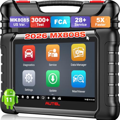
- 📌【We are Here for You】Dear valued customer, please be...
- 🚀【5X Faster Next-Level Hardware, Same as MK900/ MX...
- 🔥【3000+ Active Tests = MK900/MK900BT but...
- 📢【2026 U.S. Version, All-in-One as MK808S/ MK808Z...
- 🔥【28+ Hot Services for 150+ Brands】Same as MaxiCOM...
If the PDF is very large, it may not load in the preview below.
Some older TSBs had multiple PDFs — visit the NHTSA Website to view all PDFs.
If the TSB PDF does not show, download or view it on the NHTSA Website.
Click on the (+) Plus Sign
Then Click on Associated Document(s)
Search NHTSA Database for Recalls
Search NHTSA Database for Vehicle Investigations
View Latest Vehicle Investigations
Search NHTSA Database for Vehicle Complaints
View Latest Vehicle Complaints
TSB/Document ID: FS-2016-06
Replacement Service Bulletin Number:
MFR Communication Date: 2016-12-20
MFR Internal Campaign ID/Software Version:
Communication Type: Service Bulletin/Repair Instructions
NHTSA Components: STEERING
MFR Component System:
MFR Component Subsystem:
Previous TSB | Next TSB |

- [Notice] When you receive a used device, it may be a customer return resold by Amazon without inspection. You can exchange it for a new one through Amazon. As this situation is unavoidable, we sincerely apologize. For any issues, contacting us via Amazon's "Messages" is the best way. THINKSCAN 689BT Bidirectional Scan Tool Can Be Used Immediately After It is Turned On, Without Complicated Registration Process, Which is More Convenient & Quick.
- Full Bi-Directional Control & 3000+ Active Tests: Take control and test components like actuators, fuel injectors, relays, and cooling fans in real time. You’ll quickly see if the problem is in the part itself or the control module — saving you hours of guesswork and frustrating trial-and-error.
- Advanced ECU Coding Capabilities: Handle module matching and hidden feature activation with confidence. When you replace an ECU or want to customize settings, this obd2 scanner diagnostic bi directional tool gives you the professional-level capabilities you need without the dealership price tag.
- 34+ Useful Reset and Maintenance Functions: Complete everyday service tasks smoothly with a wide range of helpful reset and maintenance functions. Whether you’re keeping up with regular upkeep or tackling a specific job, this scanner makes maintenance simpler and less stressful for both DIYers and pros.
- Comprehensive Full System Diagnostics: Diagnose every major system — Engine, Transmission
 , ABS, SRS, TPMS, and more — all in one place. Finally stop wondering if you’re missing something important; get the full picture and clear codes with ease.

- Top Reasons to Choose the D7S OBD2 Scanner: XTOOL D7S car scan tool, an upgrade of XTOOL D7, offers comprehensive features for automotive technicians, workshops, and DIY enthusiasts 1. Upgraded Hardware: 2+64GB memory, rear camera, intuitive interface, foldable bracket 2. Complete Diagnostics: FCA Autoauth, OE-level all system scan, 39+ maintenance services, 4K+ bidirectional, CANFD/DoIP protocol 3. Advanced Capabilities: ECU coding, PMI functions 4. Wide Compatibility: Support 10,000+ models, covering 99% vehicle brands 5. Multi-language: Available in 22+ languages, No IP Restrictions 6. 3-Year Updates: Save 300 bucks on software updates for the latest features and optimizations
- 2026 Upgraded D7S Car Scanner Features: The newly 2026 D7S V2.0 scanner for car brings exciting features for advanced vehicle diagnostics and enhanced user experience 1. FCA AutoAuth: Now supports FCA SGW module for Chrysler, for Jeep, for Dodge (2018+), for Fiat (2017+), enabling faster vehicle communication without gateway restrictions 2. PMI (Offline ECU Programming): Allows for Ford, for Lincoln, and for Mazda ECU programming for new modules 3. Optimized Diagnostic Report 2.0: Personalized reports with logos and customer info for auto shops. Note: Compatibility varies by cars, please check before order
- Cost-effective ECU Coding Scan Tool for Specific Brands: Enhance your vehicle's performance with XTOOL D7S! This obd2 scanner all systems bidirectional offers advanced capabilities at an affordable price, supports online for BMW, for Benz and offline for BENZ, for MIT, along with PMI functions for Ford, for Mazda, and for Lincoln. Ideal for technicians and DIY enthusiasts, this automotive scanner diagnostic tool optimizes vehicle performance and enhances the driving experience. Note: Not for all cars and modules, please send car VIN to check the compatibility before purchase
- OE All System Diagnostic & 8 Pids Graphing: XTOOL D7S is a comprehensive all system bi directional obd2 scanner that delivers dealer-level diagnostics, completely controlling over your vehicle’s performance and health. This automotive scan tool can read and clear DTCs, view live data and ECU information, retrieve freeze frames, and perform active tests and full obd2 functions. This bi-directional scan tool can can identify your vehicle's make, model, and year information with just one click and show up to 8 PIDs live data with options for CSV viewing, playback, and recording for in-depth analysis. It is easy-to-use for both professionals and beginners, helping pinpoint issues efficiently
- 3 Years Software Update, Value for Money: With 3 years of software updates and 22+ languages(no IP restrictions), XTOOL D7S auto scanner code scanner ensures ongoing compatibility for the latest car models and improved diagnostic functions. This all system vehicle diagnostic scanner comes with a 30-day return policy and a 24-month repair for dependable performance. XTOOL are dedicated to your satisfaction, so enjoy seamless support and lifetime expert assistance. Should you encounter any issues or concerns, don’t hesitate to reach out XTOOL. D7S with newest update with 22 languages freely transfer without authorization, check details from setting-language or from XTOOL

- 【✅Compared to BOSSCOMM IF742, IF745 Offers Full-System Diagnostics】The BOSSCOMM IF745 car diagnostic scanner is an upgraded model of IF742. In addition to supporting all OBD2 Code Reader functions and 6 reset options (ABS/EPB/SAS/BMS/Oil/Throttle), it expands diagnostics from 4 systems (Check Engine/ABS/SRS/Transmission) to vehicle All systems, including Steering, Suspension, and Body Electronics. This provides deeper, more comprehensive diagnostic capabilities.
- 【✨6 Essential Resets: ABS Bleeding, Oil, EPB, SAS, Throttle, BMS】The BOSSCOMM IF745 obd2 scanner diagnostic tool swiftly purges air from brake lines to restore braking sensitivity, fine-tunes maintenance cycles to eliminate false alerts, resolves parking brake issues with one-click control, recalibrates steering sensors for stability, optimizes engine idling/acceleration for smoother performance, and deeply resets battery systems to extend lifespan and range via precise parameter adjustments.❗NOTE: Does NOT support bidirectional control, coding, or programming.
- 【✨Deep Diagnostics for All Vehicle System Modules】Beyond code reading/clearing and ECU information retrieval, our all-in-one data stream feature lets you inspect all current fault codes and their locations across the vehicle’s systems. This vehicle code reader helps you turn off dashboard warning lights and perform a comprehensive self-check of your car at home—no more back-and-forth trips to the repair shop or hefty inspection fees.
- 【✨10 OBD2 Functions】The BOSSCOMM IF745 scan tool’s DTC Lookup instantly translates fault codes into user-friendly explanations, its I/M Readiness feature streamlines emissions testing with a single tap, and Freeze Frame lets you pinpoint the exact moment of a fault for in-depth root-cause diagnosis. Combined with a live data dashboard and advanced diagnostics (O2S, OBMon, EVAP), it delivers comprehensive insights for confident troubleshooting.
- 【✨10,000+ Car Models, AutoVIN, 13 Languages】The BOSSCOMM IF745 vehicle scanner diagnostic tool covers 73+ global car brands and offers support in 13 languages, making it perfect for DIYers, auto mechanics, or as a thoughtful gift. With a single-click AutoVIN feature, it instantly retrieves vehicle serial numbers, streamlining diagnostics for users globally. This adaptable tool balances user-friendliness with precision, catering to both personal and professional requirements.✅Unsure about compatibility? Compatibility will vary on vehicles' model and year, pls reach us via 📧 [email protected] 📧 before purchase.
This product presentation was made with AAWP plugin.