
NHTSA ID Number: 11031972
Manufacturer Communication Number: SF706-DLR LTR
TSB/Document Date: 2026-05-02
Summary
Revised Field Service campaign for Cascadia Axle Conversion: Adaptive Tandem (AT) 6x4 to New Final Drive (NFD)
Tighten the U-bolt nuts just enough to allow the spring to move a bit side-to-side for axle installation.
eo on ea an FF YN
Remove the rear axle oil plug and install the temperature sensor. Ensure it is in the same position
as the old axle.
_
o
Inspect the axle for oil and verify that the oil level is below the weld point. If the new axle does not have a sensor
guard installed, weld a guard in place to protect the axle temperature sensor.
11. Top off axle oil to compensate for any oil lost after installing the sensor.
12. Install the new brass brake hose fittings in proper ports for service and parking brake chambers.
13. Install the rear shocks using the original fasteners at the spring side.
14. Install the axle vent tube.
15. Place the new lateral rod bolts from the kit through the tower and secure them with a tie strap. This provides clearance
for the bolts.
Craning the Old Rear Drive Axle into the Shipping Crate
1. Attach the overhead crane/chain to the old axle.
2. Crane the old rear drive axle and place it in the shipping crate for return.
3. | Take the crane to the new rear drive axle sitting on the jack stand rack and place the axle on the floor for installation
at a later step.
4. Lift and crane the new matching forward drive axle from the shipping crate and place on the jack stand rack.
Removal of the Forward Drive Axle from the Chassis
IMPORTANT: All drive tires must be discarded and replaced with new tires.
1. Disconnect the rear axle ABS sensor connections.
2. Disconnect the axle temperature sensor wiring and cut the tie straps that secure the wiring to the axles.
3. Raise the chassis and roll the dolly under the forward drive axle and lower the chassis to rest the axle on the dolly.
Page 14
Daimler Truck
North America LLC Field Service Campaign
SF706 A-B
Creation Date: February 2026
Revision Date: April 2026
Disconnect the air hoses from the brake chambers.
Remove the inter-axle driveline from the back of the forward drive axle.
Remove the suspension leveling rod.
Remove only the upper mounting bolts of the shock from the forward drive axle. Save the fasteners for installation.
Remove only the air bag bell nuts and washers from the forward drive axle. Save the fasteners for installation.
Remove the two bolts that secure the lateral rod to the drive axle tower.
Remove the bolts from the spring eyes for the forward drive axle.
Lift the chassis from the axle, support the frame, and roll the axle out from under the vehicle.
Leave the axle on the dolly to facilitate removal of the axle components.
Rest the chassis on the jack stands for safety.
Removal of Components from the Forward Drive Axle
1.
2
3
4.
5
6
Remove the shocks from the springs. Save the shocks and fasteners for installation.
Remove the springs. Save the springs along with the axle top and bottom spring pad for installation.
Discard the existing axle seat, U-bolts, nuts, and washers.
Remove the axle temperature sensor and save the sensor for installation.
Remove the axle vent tube and save for installation.
After the components are removed, crane the old forward drive axle and place it into the shipping crate.
Building Up the Forward Drive Axle on the Jack Stand Rack
NOTE: Refer to the Workshop Manual, Group 00 General Information, for Torque Specifications.
1.
eo ono nF Y ND
_
o
Remove two axle seats from the kit.
Remove four U-bolts, eight washers, and nuts from the kit.
Place the axle stop cast on the top axle housing in position.
Hang the U-bolts on the top axle stop pads on the axle.
Place the new axle seat on top of the spring in proper position. The seat has directional indicators.
Install the spring and pad with the thick end of the new axle seat on the aft side per D16-20089-001.
Install new U-bolts, nuts, and washers to hold the spring in place.
Verify the top axle pad is in the proper location.
Tighten the U-bolt nuts just enough to allow the spring to move a bit side-to-side for axle installation.
Remove the axle oil plug and install the temperature sensor.
Page 15
Daimler Truck
North America LLC Field Service Campaign
SF706 A-B
Creation Date: February 2026
Revision Date: April 2026
11.
12.
13.
14.
15.
16.
17.
18.
19.
20.
Inspect the axle for oil and verify that the oil level is below the weld point. If the new axle does not have a sensor guard
installed, weld a guard in place to protect the axle temperature sensor.
Top off axle oil to compensate for any oil lost after installing the sensor.
Install the new brass brake hose fittings in proper ports for service and parking brake chambers.
Install the rear shocks using the original fasteners at the spring side.
Install the axle vent tube.
Crane the new forward drive axle and place on the axle hang dolly.
Install the inter-axle driveline on the back of the forward drive axle and tighten the fasteners.
Install the main driveline on the front of the forward drive axle and tighten the fasteners.
Place the front of the main driveline slip joint/yoke on the small dolly.
Place new lateral rod bolts from the kit through the tower and secure them with a tie strap. This provides clearance for
the bolts.
Reworking the Frame for Lateral Rod / Reinforcement Plates
1.
2
3.
4.
5
Remove the bolts that attach both forward and rear lateral rods and saddles to the frame.
Remove the shock bracket from the right-hand rear axle frame.
Remove the right-hand frame axle stop casting by cutting the four frame huck bolts.
Remove the left-hand forward shock bracket.
Remove the left-hand forward frame axle stop casting from frame by cutting the four frame huck bolts.
Installation of Frame Reinforcement Plates for Axle Lateral Rods
1.
Place and align the appropriate reinforcement plate on the right-hand side frame rail to relocate the lateral rod for the
rear-rear drive axle.
Using the plate as a template, position it on the outside of the frame rail, aligning the three holes for the frame axle
stop.
Once the holes are aligned, install temporary bolts and tighten them, leaving the frame axle stop off for now to keep
the plate properly located.
Place and align the appropriate reinforcement plate on the left-hand forward frame rail to relocate the lateral rod for
the forward-rear drive axle.
Using the plate as a template, position it on the outside of the frame rail, aligning the three holes for the frame axle
stop.
Once the holes are aligned, install temporary bolts and tighten them, leaving the axle stop off for now to keep the plate
properly located.
Page 16
Daimler Truck
North America LLC Field Service Campaign
SF706 A-B
Creation Date: February 2026
Revision Date: April 2026
7. Use a 5/8-inch mag drill or equivalent to drill out the required holes in the left-hand forward frame through the holes
for the lateral rod and reinforcement plate. Use the old plate as a drilling guide. See Fig. 7.
12/15/2025 f330509
Fig. 7, Left-Hand Forward Lateral Rod and Bolt Installation After Drilling Is Completed
Page 17
Daimler Truck
North America LLC Field Service Campaign
SF706 A-B
Creation Date: February 2026
Revision Date: April 2026
8. Use a 5/8-inch mag drill or equivalent to drill out the required holes in the right-hand frame through the holes for the
lateral rod and reinforcement plate. Use the old plate as a drilling guide. See Fig. 8.
ff
ey a
12/15/2025 f330510
Fig. 8, Right-Hand Lateral Rod and Bolt Installation After Drilling Is Completed
Page 18
Daimler Truck
North America LLC Field Service Campaign
SF706 A-B
Creation Date: February 2026
Revision Date: April 2026
9.
10.
11.
12.
13.
After drilling, remove the temporary bolts and move the reinforcement plates to the inside of the frame rail where the
holes were drilled.
Install the shock mount and axle frame stop bracket using the proper length bolts. Fill any remaining holes in the frame
rails with grade 8 hardware following the same guidelines, ensuring at least 3 full threads extend past the nuts.
Repeat this process for each reinforcement plate on the rear drive axle at the opposite frame rail.
Tighten all bolts securing the reinforcement plates on both frame rails, except the lateral rod and saddle bolts, to allow
axle installation.
Replace any warning labels that were damaged/covered by the work being performed. Relocate labels if necessary.
Installation of the Forward Drive Axle into the Chassis
1.
o on eon F Yo BS
= —_
Ss oO
. .
12.
13.
Raise the chassis with an overhead hoist or a four-point lift.
Roll the forward drive axle that is on the axle dolly under the chassis.
Extend the shocks out to the max position.
As the chassis is being lowered on to the axle, line up the suspension air bag bell studs into the rear spring.
Install the airbag stud using the new nuts and washers and tighten.
Continue to lower the chassis on to the axle, lining up the front spring eyes with the castings.
Insert the new fasteners into the front spring eyes, not the castings.
Line up the top shock into the frame shock bracket, and secure using the original fasteners.
Line up and install the new fasteners that attach the lateral rod to the axle tower.
Tighten the front spring eyes, shock bolts, and lateral rod bolts at the axle towers and the frame.
Raise/support the main driveline. Fasten it to the midship bearing support bracket using new the new fasteners
provided per D09-11946-000. Torque fasteners to 148 Ibf-ft (200 N-m).
Raise the chassis and remove the dolly.
Rest the chassis on the jack stands for safety.
Crane the Rear Drive Axle on to the Installation Dolly
Installation of Rear Drive Axle into the Chassis
1.
2
3.
4
5
Chain the forward drive axle to the frame so the axle weight doesn't hang on the suspension and damage it.
Raise the chassis with an overhead hoist.
Roll the rear drive axle that is on the axle dolly under the chassis.
Extend the shocks out to the max position.
As the chassis is being lowered on to the axle, line up the suspension air bag bell studs into the rear spring.
Page 19
Daimler Truck
North America LLC Field Service Campaign
SF706 A-B
Creation Date: February 2026
Revision Date: April 2026
Install the airbag stud using the new nuts and washers and tighten.
Continue to lower the chassis on to the axle, lining up the front spring eyes with the spring hangers.
Insert the new fasteners from the hanger side into the front spring eyes.
Line up the top shock into the frame shock bracket, and secure using the original fasteners.
10. Line up and install the new fasteners that attach the lateral rod to the axle tower.
11. Tighten the front spring eyes, shock bolts, and lateral rod bolts at the axle towers and the frame.
12. Raise the chassis with an overhead hoist and set the chassis on jack stands under the forward drive hubs.
13. Install the new interaxle driveshaft using the new hardware supplied per DO9-11936-001. Torque fasteners to
125 Ibf-ft (170 N-m).
Connecting the ABS / Plumbing to Axles
1. Connect the hoses to the hose fittings on the service and parking brake chambers.
2. Use the original clips or butterfly straps to route and connect the ABS harness at all four wheel ends.
3. While in this area of the truck, install the new suspension rod from the kit between the suspension-levelling valve and
the forward drive axle.
Tightening the Fasteners
_
.
Hand-tighten the axle U-bolt high nuts.
2. Tighten the nuts in a diagonal pattern 60 Ibf-ft (81 N-m).
3. In the same diagonal pattern, tighten the nuts 200 Ibf-ft (271 N-m).
4. Finally, tighten the nuts 420 to 500 Ibf-ft (569 to 678 N-m).
5. Check the rear axle oil levels.
Installation of the Rear Wheels and New Tires / Inflation and Monitoring System
1. Install the TPMS sensors on the rear wheel ends, if originally equipped.
2. _ Install the wheels and new tires.
3. Tighten the wheel lug nuts 500 Ibf-ft (678 N-m).
4. Install all rear axle wheel flow below covers (hub wheel covers), if originally equipped.
5
Install the rear 1/4 fender aero fairings, if originally equipped.
Page 20
Daimler Truck
North America LLC Field Service Campaign
SF706 A-B
Creation Date: February 2026
Revision Date: April 2026
Plumbing the Manual Inter-Axle Switch and Plumbing
NOTE: For vehicles equipped with Driver Control Differential Lock (DCDL), connect the existing DCDL lines to the new
axles.
1. Drain all air from the system. Remove the plumbing from the solenoids above the rear axle, then remove the solenoids.
Save the 1/4-inch white airline for later use (if this airline is not long enough, then a new airline may be needed for
later use instead.)
2. Remove the yellow supply line for solenoids from the frame, then remove the Y-connector and two short yellow lines.
Use a section of the removed yellow line to replace the Y-connector and two short yellow section lines. See Fig. 9.
li sl AY iy .
01/23/2026 330505
A. Remove the supply line for solenoids from the frame. C. Remove the two short yellow lines.
B. Remove the Y-connector.
Fig. 9, Y-Connector
Page 21
Daimler Truck
North America LLC Field Service Campaign
SF706 A-B
Creation Date: February 2026
Revision Date: April 2026
. | Move the old temperature sensor and differential lock harnesses aside as far as possible.
4. Pull the dash panels including the ICU to route the dash harness and airline for the dash switch. See Fig. 10.
08/12/2025 #330506
Fig. 10, Dash Side Panel
Page 22
Daimler Truck
North America LLC Field Service Campaign
SF706 A-B
Creation Date: February 2026
Revision Date: April 2026
5.
10.
11.
12.
13.
14.
Use wiring diagram G06-92166-002 to connect the harness. The splice packs can be accessed from the tunnel on
the passenger side. The splice pack locations are shown in Fig. 11.
08/12/2025 330507
Fig. 11, Splice Packs
The old axle harness, shown in drawing G66-08370-001, may be incorrectly routed. Verify the circuit number before
removing the connector. The pins 30 and 43 are in BHM_1A instead of BHB_1B. Remove pin 30 from the dash side.
Cut out a new spot in the dash for the switch, then install the switch.
Use the %-inch white airline saved earlier (if long enough), or use a new %-inch white airline, and route it into the
passthrough and then to the switch. Install the dash panels.
Use the 1/4-inch coupler from the kit and run about 25 feet of the 1/4-inch white airline to the differential lock.
The temperature sensor harness is routed differently due to new axles. Wrap the temperature sensor harness back to
where they split and wrap 2 feet back on the axle lock sensor harness.
Put the split for the temperature sensor harness at the crossmember, right behind the batteries.
Run and secure both the harnesses to the split point, then wrap both the harnesses together. Two unused brackets
may be found on the crossmember, use the brackets by flipping them around so the wires do not rub on the frame.
Run the harness to the front of vehicle and cut to length, there may be almost 20 ft of extra wire. Put new pins on wires
and pin them per the wiring diagram. The connector locations are shown in Fig. 11.
Remove all the old axle harness pins from chassis side connectors, then install the plugs.
Page 23
Daimler Truck
North America LLC Field Service Campaign
SF706 A-B
Creation Date: February 2026
Revision Date: April 2026
15. Start the engine and check for air leaks. Operate the inter-axle lock and DCDL (if equipped), checking for air leaks.
Release the parking brakes and check for air leaks. Have an assistant apply the brake pedal and check for air leaks.
16. Perform the ride height calibration.
17. Verify proper functioning of the interaxle lock and differential lock (DCDL), if equipped.
Alignment / Tracking and Spacing of the Rear Axle
1. Set the tracking and spacing of the rear axles.
Perform an axle alignment. Refer to the workshop manual.

- 【TURN OFF CEL】 This AL319 car scanner diagnostic tool...
- 【EXTENSIVE APPLICATION】 Autel AL319 Compatible with...
- 【FOR END USER & DIYERS】 This error code reader AL319 is...
- 【USER-FRIENDLY DESIGN】 This OBD2 scanner and check...
- 【HIGH-QUALITY SERVICES】 12 months war.ranty from the...
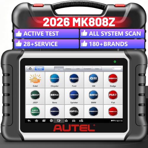
- 🔥🔥🔥🚀 【2026 Professional All-System Diagnostic...
- 🛠【28+ Essential Service Resets & Special Functions...
- ⚡ 【Advanced Bidirectional Active Test for Precise Fault...
- 🌐 【Wide Vehicle Coverage & 2026 New Car Support with...
- 💻 【Powerful Hardware & FCA
 SGW Bypass for Enhanced...
 SGW Bypass for Enhanced...
If the PDF is very large, it may not load in the preview below.
Some older TSBs had multiple PDFs — visit the NHTSA Website to view all PDFs.
If the TSB PDF does not show, download or view it on the NHTSA Website.
Click on the (+) Plus Sign
Then Click on Associated Document(s)
Search NHTSA Database for Recalls
Search NHTSA Database for Vehicle Investigations
View Latest Vehicle Investigations
Search NHTSA Database for Vehicle Complaints
View Latest Vehicle Complaints
TSB/Document ID: SF706-DLR LTR
Replacement Service Bulletin Number:
MFR Communication Date: 2026-04-15
MFR Internal Campaign ID/Software Version:
Communication Type: Service Bulletin/Repair Instructions
NHTSA Components: POWER TRAIN
MFR Component System:
MFR Component Subsystem:
Previous TSB | Next TSB |

- [Notice] When you receive a used device, it may be a customer return resold by Amazon without inspection. You can exchange it for a new one through Amazon. As this situation is unavoidable, we sincerely apologize. For any issues, contacting us via Amazon's "Messages" is the best way. THINKSCAN 689BT Bidirectional Scan Tool Can Be Used Immediately After It is Turned On, Without Complicated Registration Process, Which is More Convenient & Quick.
- Full Bi-Directional Control & 3000+ Active Tests: Take control and test components like actuators, fuel injectors, relays, and cooling fans in real time. You’ll quickly see if the problem is in the part itself or the control module — saving you hours of guesswork and frustrating trial-and-error.
- Advanced ECU Coding Capabilities: Handle module matching and hidden feature activation with confidence. When you replace an ECU or want to customize settings, this obd2 scanner diagnostic bi directional tool gives you the professional-level capabilities you need without the dealership price tag.
- 34+ Useful Reset and Maintenance Functions: Complete everyday service tasks smoothly with a wide range of helpful reset and maintenance functions. Whether you’re keeping up with regular upkeep or tackling a specific job, this scanner makes maintenance simpler and less stressful for both DIYers and pros.
- Comprehensive Full System Diagnostics: Diagnose every major system — Engine, Transmission, ABS, SRS, TPMS, and more — all in one place. Finally stop wondering if you’re missing something important; get the full picture and clear codes with ease.

- Top Reasons to Choose the D7S OBD2 Scanner: XTOOL D7S car scan tool, an upgrade of XTOOL D7, offers comprehensive features for automotive technicians, workshops, and DIY enthusiasts 1. Upgraded Hardware: 2+64GB memory, rear camera, intuitive interface, foldable bracket 2. Complete Diagnostics: FCA Autoauth, OE-level all system scan, 39+ maintenance services, 4K+ bidirectional, CANFD/DoIP protocol 3. Advanced Capabilities: ECU coding, PMI functions 4. Wide Compatibility: Support 10,000+ models, covering 99% vehicle brands 5. Multi-language: Available in 22+ languages, No IP Restrictions 6. 3-Year Updates: Save 300 bucks on software updates for the latest features and optimizations
- 2026 Upgraded D7S Car Scanner Features: The newly 2026 D7S V2.0 scanner for car brings exciting features for advanced vehicle diagnostics and enhanced user experience 1. FCA AutoAuth: Now supports FCA SGW module for Chrysler, for Jeep, for Dodge (2018+), for Fiat (2017+), enabling faster vehicle communication without gateway restrictions 2. PMI (Offline ECU Programming): Allows for Ford, for Lincoln, and for Mazda ECU programming for new modules 3. Optimized Diagnostic Report 2.0: Personalized reports with logos and customer info for auto shops. Note: Compatibility varies by cars, please check before order
- Cost-effective ECU Coding Scan Tool for Specific Brands: Enhance your vehicle's performance with XTOOL D7S! This obd2 scanner all systems bidirectional offers advanced capabilities at an affordable price, supports online for BMW, for Benz and offline for BENZ, for MIT, along with PMI functions for Ford, for Mazda, and for Lincoln. Ideal for technicians and DIY enthusiasts, this automotive scanner diagnostic tool optimizes vehicle performance and enhances the driving experience. Note: Not for all cars and modules, please send car VIN to check the compatibility before purchase
- OE All System Diagnostic & 8 Pids Graphing: XTOOL D7S is a comprehensive all system bi directional obd2 scanner that delivers dealer-level diagnostics, completely controlling over your vehicle’s performance and health. This automotive scan tool can read and clear DTCs, view live data and ECU information, retrieve freeze frames, and perform active tests and full obd2 functions. This bi-directional scan tool can can identify your vehicle's make, model, and year information with just one click and show up to 8 PIDs live data with options for CSV viewing, playback, and recording for in-depth analysis. It is easy-to-use for both professionals and beginners, helping pinpoint issues efficiently
- 3 Years Software Update, Value for Money: With 3 years of software updates and 22+ languages(no IP restrictions), XTOOL D7S auto scanner code scanner ensures ongoing compatibility for the latest car models and improved diagnostic functions. This all system vehicle diagnostic scanner comes with a 30-day return policy and a 24-month repair for dependable performance. XTOOL are dedicated to your satisfaction, so enjoy seamless support and lifetime expert assistance. Should you encounter any issues or concerns, don’t hesitate to reach out XTOOL. D7S with newest update with 22 languages freely transfer without authorization, check details from setting-language or from XTOOL

- 🔥 Historical lowest pr-ice now on sa-le--hot se-lling.
- 【🎈𝗜𝗙𝟳𝟰𝟱 𝗽𝗲𝗿𝗳𝗼𝗿𝗺𝘀 𝟲 𝗲𝘀𝘀𝗲𝗻𝘁𝗶𝗮𝗹 𝗿𝗲𝘀𝗲𝘁 𝗳𝘂𝗻𝗰𝘁𝗶𝗼𝗻𝘀—𝗔𝗕𝗦 𝗕𝗹𝗲𝗲𝗱𝗶𝗻𝗴, 𝗢𝗶𝗹 𝗥𝗲𝘀𝗲𝘁, 𝗘𝗣𝗕, 𝗦𝗔𝗦, 𝗧𝗵𝗿𝗼𝘁𝘁𝗹𝗲 𝗥𝗲𝗹𝗲𝗮𝗿𝗻, 𝗮𝗻𝗱 𝗕𝗠𝗦—𝗽𝘂𝘁𝘁𝗶𝗻𝗴 𝗽𝗿𝗼𝗳𝗲𝘀𝘀𝗶𝗼𝗻𝗮𝗹-𝗴𝗿𝗮𝗱𝗲 𝗺𝗮𝗶𝗻𝘁𝗲𝗻𝗮𝗻𝗰𝗲 𝗯𝗮𝗰𝗸 𝗶𝗻 𝘆𝗼𝘂𝗿 𝗵𝗮𝗻𝗱𝘀.】Spongy brakes? Stuck oil light? Parking brake won't release? Off-center steering? Rough idle after battery disconnect? Draining battery? IF745 handles all with a few taps. One tool covers six dealer-level resets, saving hundreds in labor costs. ❗ NOTE: Does NOT support bidirectional control, coding, or programming.
- 【✨ 𝗜𝗙𝟳𝟰𝟱 𝗴𝗼𝗲𝘀 𝗯𝗲𝘆𝗼𝗻𝗱 𝗯𝗮𝘀𝗶𝗰 𝗰𝗼𝗱𝗲 𝗿𝗲𝗮𝗱𝗶𝗻𝗴 𝘄𝗶𝘁𝗵 𝟭𝟬 𝗶𝗻𝘁𝗲𝗴𝗿𝗮𝘁𝗲𝗱 𝗳𝘂𝗻𝗰𝘁𝗶𝗼𝗻𝘀—𝗗𝗧𝗖 𝗟𝗼𝗼𝗸𝘂𝗽, 𝗜/𝗠 𝗥𝗲𝗮𝗱𝗶𝗻𝗲𝘀𝘀, 𝗙𝗿𝗲𝗲𝘇𝗲 𝗙𝗿𝗮𝗺𝗲, 𝗟𝗶𝘃𝗲 𝗗𝗮𝘁𝗮, 𝗢𝟮𝗦, 𝗢𝗕𝗠, 𝗘𝗩𝗔𝗣, 𝗮𝗻𝗱 𝗺𝗼𝗿𝗲. 】Pulling a code tells you something is wrong. IF745 tells you what the code means, when the fault happened, and what data surrounds it. Pass emissions with one I/M Readiness tap. Freeze the fault moment with Freeze Frame. Monitor live sensor data in real time. Turn cryptic codes into clear answers.
- 【🛒 𝗜𝗙𝟳𝟰𝟱 𝗽𝗲𝗿𝗳𝗼𝗿𝗺𝘀 𝗳𝘂𝗹𝗹-𝘀𝘆𝘀𝘁𝗲𝗺 𝗱𝗶𝗮𝗴𝗻𝗼𝘀𝘁𝗶𝗰𝘀 𝗮𝗰𝗿𝗼𝘀𝘀 𝗮𝗹𝗹 𝗺𝗼𝗱𝘂𝗹𝗲𝘀—𝗲𝗻𝗴𝗶𝗻𝗲, 𝗔𝗕𝗦, 𝗮𝗶𝗿𝗯𝗮𝗴, 𝘁𝗿𝗮𝗻𝘀𝗺𝗶𝘀𝘀𝗶𝗼𝗻, 𝘀𝘁𝗲𝗲𝗿𝗶𝗻𝗴, 𝘀𝘂𝘀𝗽𝗲𝗻𝘀𝗶𝗼𝗻, 𝗯𝗼𝗱𝘆 𝗲𝗹𝗲𝗰𝘁𝗿𝗼𝗻𝗶𝗰𝘀, 𝗮𝗻𝗱 𝗺𝗼𝗿𝗲. 】Warning lights on but you don't know why? Skip the $100+ diagnostic fee at the shop. Run a complete self-check from your driveway. IF745 reads and clears fault codes, retrieves ECU info, and displays live data from every accessible module—delivering a full vehicle health report in minutes, without leaving home.
- 【✅𝗜𝗙𝟳𝟰𝟱 𝗳𝗲𝗮𝘁𝘂𝗿𝗲𝘀 𝗮 𝟳-𝗶𝗻𝗰𝗵 𝗱𝗶𝘀𝗽𝗹𝗮𝘆, 𝗲𝗿𝗴𝗼𝗻𝗼𝗺𝗶𝗰 𝗱𝗲𝘀𝗶𝗴𝗻, 𝗪𝗶-𝗙𝗶 𝘂𝗽𝗱𝗮𝘁𝗲𝘀, 𝗮𝗻𝗱 𝘇𝗲𝗿𝗼 𝘀𝘂𝗯𝘀𝗰𝗿𝗶𝗽𝘁𝗶𝗼𝗻 𝗳𝗲𝗲𝘀 𝗳𝗼𝗿 𝗵𝗮𝘀𝘀𝗹𝗲-𝗳𝗿𝗲𝗲 𝗱𝗶𝗮𝗴𝗻𝗼𝘀𝘁𝗶𝗰𝘀.】Large screen means no squinting. Intuitive navigation and customizable data displays put key info at your fingertips. Wi-Fi delivers lifetime free updates without a computer. No recurring fees. No hidden costs. Just a reliable tool that works as hard as you do.
This product presentation was made with AAWP plugin.