
NHTSA ID Number: 11031407
Manufacturer Communication Number: ITS61673
TSB/Document Date: 2026-04-21
Summary
Instructions for removing the HVDM box for supplier component replacement.
INSTRUCTION TO SERVICE
ITS: 61673
DATE 4/17/2026
SECTION:
260U – Battery System
SUBJECT:
HVDM box component replacement
ISSUE:
Internal component failure in the HVDM unit due to cold weather
SUMMARY:
Remove HVDM box for supplier component replacement
ITS61673
Ref. NHTSA Recall No.
Not Applicable
Ref. Transport Canada Recall No.
Not Applicable
THIS ITS DOCUMENT SHOULD BE RETAINED AND REFERRED TO FOR FUTURE MAINTENANCE UNTIL
THE NEW FLYER PARTS AND/OR SERVICE MANUAL IS UPDATED TO REFLECT WORK DONE AS A
RESULT OF THIS DOCUMENT. ENSURE THAT THIS DOCUMENT IS AVAILABLE FOR PARTS AND
MAINTENANCE STAFF GOING FORWARD.
This document and the contents discussed herein are the confidential and proprietary information of New Flyer Industries Canada
ULC and New Flyer of America Inc. and are disclosed by New Flyer in confidence. This document and the contents herein are not
to be disclosed by the intended recipient without the prior written authorization of New Flyer. Any unauthorized disclosure,
reproduction or other distribution of this document or information strictly prohibited and may result in action being taken against
the party making the unauthorized disclosure. This document and all copies hereof must be returned to New Flyer upon request.
INSTRUCTION TO SERVICE
ITS61673
PROCEDURE:
Only trained personnel shall supervise and perform the High Voltage system testing,
servicing and troubleshooting contained in this procedure.
1.
2.
3.
4.
5.
6.
Ensure to apply the parking brake.
Turn the master run switch to the off position and wait 5 minutes before proceeding.
Turn the 12/24V battery disconnect and HV Interlock switch to the “OFF” position.
Lock and tag the electrical system of the bus out and retain the key. See Figure 1.
Ensure to the wear proper PPE.
Install a Lockout/Tagout Steering wheel cover as required.
NOTE: Refer to the Lockout/Tagout Procedure in section 1 of your Preventive Maintenance Manual
or section 9 of your Service Manual for additional information.
NOTE: Use commercially available lock out equipment and tags being sure to follow any local laws
or workplace procedures.
NOTE: Refer to New Flyer High Voltage Safety Guidelines and Procedures Document 532295
(Appendix A) when completing installation or service work on high voltage power cables.
Figure 1: Lockout Tagout location reference.
ITS61673
Page 2 of 14
April 17,2026
INSTRUCTION TO SERVICE
ITS61673
7. Ensure no voltage is present before work begins. Gain access to hybrid cover HVDM/JUNC box EGEN Assy
Item 2. See Figure 2.
8. Once cover is open, gain access to HVDM box Item 8. See Figure 2.
Figure 2: HDVM box location reference.
ITS61673
Page 3 of 14
April 17,2026
INSTRUCTION TO SERVICE
ITS61673
9. Disconnect HV RESS cable (yellow cable) from side connector on the HVDM. See Figure 3.
10. Remove HVDM cover plate hardware and set aside for reinstallation. Remove Cover. See Figure 3.
Disconnect
RESS cable
Remove
Hardware
Figure 3: HDVM box cable disconnect location reference.
ITS61673
Page 4 of 14
April 17,2026
INSTRUCTION TO SERVICE
ITS61673
11. Ensure no Voltage present on connection. Note and disconnect location of positive and negative cable terminals
Remove Gland nuts from inside box and remove cable item 31 and 37 from HVDM box. See Figure 4.
Remove Gland nut and set
aside
Disconnect
Cable terminal
Figure 4: Disconnect cable location reference.
12. Remove HVDM mounting bolts and set aside for reinstallation. See Figure 5.
Remove
Mounting
Hardware
Figure 5: HVDM Assy mounting hardware location reference.
ITS61673
Page 5 of 14
April 17,2026
INSTRUCTION TO SERVICE
ITS61673
13. Remove HVDM box and deliver to Havis technician for rework on internal components.
14. Once rework is complete by the Havis technician, reinstall HVDM box with existing mounting hardware applying
one or two drops of loctite-243 (NF PN 081034).
Note XDE35, has 1/4 hardware (torqued to 9 ft-lb).
Note: XDE40 has 5/16 hardware (torqued to 18 ft-lb).
15. Reinstall cables Item 31 and Item 37. Reinstall Gland nuts and torque it to 89 in-lb as shown below.
See Figure 6.
16. Re-connect positive and negative cable terminal for both cables HP11HV (Item 31) and PD280 CH2 (Item 37)
and torque as shown below. See figure 6.
Figure 6: HVDM Cable terminal location reference.
ITS61673
Page 6 of 14
April 17,2026
INSTRUCTION TO SERVICE
ITS61673
17. Re-install HVDM top cover plate using existing hardware and torque to 75 in-lb. Close HVDM/JUNC box cover
and secure it using latch.
18. Clean up all tools and debris.
19. Perform Road test and return bus to service condition.
Figure 7: HVDM top plate hardware location reference.
ITS61673
Page 7 of 14
April 17,2026
INSTRUCTION TO SERVICE
ITS61673
LABOUR ESTIMATE
Operation
1
Remove HVDM box for supplier component replacement
Number of
Technician(s)
2
Hours
2
Labor Time
T X HR
4
PARTS REQUIRED
Item
Part Number
Qty.
per
Coach
Description
Units
Notes
Units
Notes
SPECIAL TOOLS REQUIRED
Item
ITS61673
Part Number
Qty.
Description
Page 8 of 14
April 17,2026
INSTRUCTION TO SERVICE
ITS61673
Appendix A – NFIL Spec 532295 - High
Voltage Safety Guidelines & Procedures for
New Flyer Battery Bus
The following provides general guidelines in relation to safety and best practices
when completing installation or servicing work on any New Flyer battery bus
vehicle platform.
This document is not meant to supersede the actual released installation and
assembly drawings and where conflicts arise, the released engineering drawings
take precedence.
Introduction
The utmost concern, while working with High Voltage (HV) systems, is the safety of yourself, other personnel and
the potential of damage to property. To minimize these risks, it is crucial to be properly trained and always
maintain a very alert, questioning and disciplined attitude without fail. As soon as your guard is lowered, then the
potential of an accident is probable that can hurt or kill yourself or someone else and possibly damage property.
What is High Voltage (HV)?
Any form of voltage that is greater than 50 volts if the person’s skin at the electrical contact points is not
compromised and not wet.
Equipment Required
ITS61673
Page 9 of 14
April 17,2026
INSTRUCTION TO SERVICE
ITS61673
The following equipment shall be required:
Digital Multimeter (DMM), 1000 volt Category II, 600 volt Category IV, 10Megohm
impedance or greater with insulated case or rubber holster
Clamp-on current probe, 1000 volt Category II, 600 volt Category IV
High Pot Tester (Hi-Pot)
Phase rotation meter
Personal Protection Equipment (PPE) appropriate for 700volt DC & 230 volt AC with
Class 00 or higher HV gloves with compatible leather over gloves. Appropriate safety
glasses as well as the face shield. The PPE shall also meet the required Arc Flash &
Arc Blast requirements. Before use, inspect the PPE in accordance with this guideline.
Adequate lighting
HV insulated mat
Two fused HV clip leads 10 inches long
Safety barricade with warning lights & "Danger High Voltage" signs
Belt tool pouch (use only to carry small components up/down a ladder)
Torque Screwdriver set
Imperial torque nut driver set
Metric torque nut driver set
Imperial 1/4" torque drive socket set
Imperial 3/8" torque drive socket set
Insulated rescue hook
ABC Fire extinguisher, 5 lb minimum, at the activity areas
Spare HV and low voltage fuses
Equipment Calibration
All test equipment must be within their calibration interval and recorded such with the respective serial numbers.
These records must be available to the Checker.
Personnel Requirement
Only trained personnel shall supervise and perform High Voltage system testing, checkout and troubleshooting.
Two personnel (one called the Checker & the other called Monitor/Recorder) shall perform Checkout Procedures,
together, to ensure safety of themselves, others nearby & for the protection of vehicle & property. Refresher
training shall be provided to these personnel on a regular basis and when new systems are to be checked by
them. The training of the personnel shall consist of:
HV & low voltage basics, intermediate & advanced electricity
HV & low voltage electrical systems of the vehicle
Shop safety practices & procedures
First aide including CPR & the use of the shop defibrillator
How to release a victim that can’t let go HV
Quickest method of shutting down HV
ITS61673
Page 10 of 14
April 17,2026
INSTRUCTION TO SERVICE
ITS61673
Fire fighting and emergency procedures
HV & arcflash safety
Organized & tidy placement of equipment & tools allowing for unrestricted
movement
Operation of Hi-pot
Operation of Phase Rotation Meter
To ensure effectiveness of training, exams of the trained material shall be required with a high passing mark of at
least 80% and a retraining of the missed 20 % on a one to one basis.
Checker Function
(Caution: The Checker must not have any health conditions that can be exacerbated when startled and must not
have any electronic implants.)
Directed by the Monitor/Recorder
Performs all preparations & checks
Wears PPE as specified by the Checkout Procedure
Performs all restorations
Vehicle Inspection
It is necessary that the vehicle to be checked out, first be visually inspected of all systems, workmanship and with
special attention to ensuring there is no HV cable or equipment damage or chafing.
High Voltage Checkout Preparation
(1) The scope of the work must be accurately defined such as a Checkout Procedure that requires
systematic steps with sign offs. Before a Checkout is performed, the Supervisor, Checker and
Monitor/Recorder must conduct a briefing of what shall transpire, identify potential hazards, resist
pressures of “is it done yet?”, anticipate problems and question possible events. If an unexpected
electrical hazard or fault occurs, during any time of the Checkout, it must be immediately reported to the
supervisor. After the Checkout is completed the same group should review the results and processes
and make proposed modifications to the procedures if required.
(2) Install Safety barricade with warning lights & signs indicating "Danger High Voltage" around the vehicle
perimeter and ensure no personnel are within the fenced perimeter during the checkout procedure.
(3) It shall always be the goal to check the systems as much as possible with all HV power OFF and Locked
Out/Tagged Out and proven as de-energized by voltage measurement using the DMM. The functionality
of the DMM must be proved before and after the verification of no HV present. Then, if possible, the HV
systems should be challenged by trying to energize them while checking that no HV appears.
(4) When it is necessary to perform tests of HV systems with the power ON, then the Working Live procedure
must be followed.
(5) The test personnel shall always rehearse the actions required in case of any possible accident scenarios.
(6) Before beginning the Checkout Procedure, the test personnel shall remove all their jewelry (including
pierced ones), watches and any electrically conductive objects on them.
PPE Requirements
The PPE voltage class, Arc Flash and Arc Blast rating shall be compatible with the voltage and Arc Flash
capability of the systems being tested. Appropriate leather glove protectors shall be worn over the HV rubber
gloves.
ITS61673
Page 11 of 14
April 17,2026
INSTRUCTION TO SERVICE
ITS61673
PPE Care & Testing
Rubber insulated PPE shall be periodically cleaned and tested in accordance with 29 CFR 1910.137 and the
appropriate ANSI/ASTM standards. HV gloves, sleeves and mats shall be tested every 6 months. PPE apparel
shall be cleaned and maintained in accordance with the manufacturer’s instructions. A record of the PPE testing
shall be maintained and available to the users.
PPE Inspection
Inspect PPE equipment, before use, for any degradation or damage and ensure that the HV gloves have been
tested every 6 months. Also perform an air pressure test on the HV gloves before and after each use. If during
PPE use a potential damaging incident occurred to the PPE, stop further testing and inspect the PPE. If at any
time the PPE is defective, reject it, and obtain an accepted one.
PPE Storage
PPE apparel should be stored lying flat, undistorted, right-side out and not folded in protective containers. The
HV mats can be rolled with an inside diameter greater than 2 inches.
Rubber HV gloves should be stored in cool, dark, dry, and free from damaging chemicals or vapors. The glove
cuffs should face downwards, without folding, in the appropriate glove bag and hung vertically.
Insulated Tools
Insulated tools should be visually inspected for insulation damage before and after each session of use.
Lockout/Tagout Procedure
The Lockout/Tagout procedure should be followed that is specified in the respective Checkout procedure. When
removing the lock and tag:
(1) The locks and tags shall be removed by the installer of them or under her/his supervision.
(2) If the installer of the locks and tags is not available, then her/his supervisor:
(a) Ensures that the installer of the locks and tags in not in the facility
(b) Contacts the installer to inform her/him that the locks and tags will be removed
(c) Reminds the installer of the lock and tag removal when she/he resumes work
Stored Energy
Personnel must always remember the characteristics of stored energy devices such as capacitors and batteries
and when energy is available from.
Working Live
To maximize safety, it is always important to perform the maximum amount of HV checkout in the de-energized
state.
When it is necessary to work with HV equipment while energized or to verify whether HV is present, the utmost
care and safety procedures must be utilized including:
(1) Wearing appropriate PPE with protector gloves over top of the HV rubber gloves
(2) Ensure all personnel, except the Checker and Monitor/Recorder, are clear of the vehicle
(3) Kneeling or standing on HV insulated mat
Energizing & De-energizing Procedure
It is critical that before any HV system is energized that a visual check be performed to ensure that all possible HV
compartments are closed and there is no debris, tools or test equipment lying on HV terminations. If there is a
certain sequence of energizing and de-energizing the HV system, then all personnel involved must be trained in
this sequence. (CAUTION: Never try to connect or disconnect circuit components such as cables, fuses,
connectors, etc while there is current flowing in the circuit.)
ITS61673
Page 12 of 14
April 17,2026
INSTRUCTION TO SERVICE
ITS61673
Electrical Injuries
Electrical injuries should be immediately reported to the first aide personnel and the supervisor. Other than
electrostatic shocks, even non-injurious electrical shocks should be reported to the supervisor. These should be
immediately investigated and documented to determine the cause and prevent the occurrence in the future.
Appendix B – NFIL PPE Categories
ITS61673
Page 13 of 14
April 17,2026
INSTRUCTION TO SERVICE
ITS61673
ITS61673
Page 14 of 14
April 17,2026
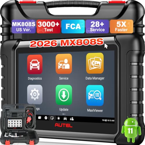
- 📌【We are Here for You】Dear valued customer, please be...
- 🚀【5X Faster Next-Level Hardware, Same as MK900/ MX...
- 🔥【3000+ Active Tests = MK900/MK900BT but...
- 📢【2026 U.S. Version, All-in-One as MK808S/ MK808Z...
- 🔥【28+ Hot Services for 150+ Brands】Same as MaxiCOM...

- 【TURN OFF CEL】 This AL319 car scanner diagnostic tool...
- 【EXTENSIVE APPLICATION】 Autel AL319 Compatible with...
- 【FOR END USER & DIYERS】 This error code reader AL319 is...
- 【USER-FRIENDLY DESIGN】 This OBD2 scanner and check...
- 【HIGH-QUALITY SERVICES】 12 months war.ranty from the...
If the PDF is very large, it may not load in the preview below.
Some older TSBs had multiple PDFs — visit the NHTSA Website to view all PDFs.
If the TSB PDF does not show, download or view it on the NHTSA Website.
Click on the (+) Plus Sign
Then Click on Associated Document(s)
Search NHTSA Database for Recalls
Search NHTSA Database for Vehicle Investigations
View Latest Vehicle Investigations
Search NHTSA Database for Vehicle Complaints
View Latest Vehicle Complaints
TSB/Document ID: ITS61673
Replacement Service Bulletin Number:
MFR Communication Date: 2026-04-17
MFR Internal Campaign ID/Software Version:
Communication Type: Service Bulletin/Repair Instructions
NHTSA Components: FUEL/PROPULSION SYSTEM
MFR Component System:
MFR Component Subsystem:
Previous TSB | Next TSB |

- [Notice] When you receive a used device, it may be a customer return resold by Amazon without inspection. You can exchange it for a new one through Amazon. As this situation is unavoidable, we sincerely apologize. For any issues, contacting us via Amazon's "Messages" is the best way. THINKSCAN 689BT Bidirectional Scan Tool Can Be Used Immediately After It is Turned On, Without Complicated Registration Process, Which is More Convenient & Quick.
- Full Bi-Directional Control & 3000+ Active Tests: Take control and test components like actuators, fuel injectors, relays, and cooling fans in real time. You’ll quickly see if the problem is in the part itself or the control module — saving you hours of guesswork and frustrating trial-and-error.
- Advanced ECU Coding Capabilities: Handle module matching and hidden feature activation with confidence. When you replace an ECU or want to customize settings, this obd2 scanner diagnostic bi directional tool gives you the professional-level capabilities you need without the dealership price tag.
- 34+ Useful Reset and Maintenance Functions: Complete everyday service tasks smoothly with a wide range of helpful reset and maintenance functions. Whether you’re keeping up with regular upkeep or tackling a specific job, this scanner makes maintenance simpler and less stressful for both DIYers and pros.
- Comprehensive Full System Diagnostics: Diagnose every major system — Engine, Transmission, ABS, SRS, TPMS, and more — all in one place. Finally stop wondering if you’re missing something important; get the full picture and clear codes with ease.

- Top Reasons to Choose the D7S OBD2 Scanner: XTOOL D7S car scan tool, an upgrade of XTOOL D7, offers comprehensive features for automotive technicians, workshops, and DIY enthusiasts 1. Upgraded Hardware: 2+64GB memory, rear camera, intuitive interface, foldable bracket 2. Complete Diagnostics: FCA
 Autoauth, OE-level all system scan, 39+ maintenance services, 4K+ bidirectional, CANFD/DoIP protocol 3. Advanced Capabilities: ECU coding, PMI functions 4. Wide Compatibility: Support 10,000+ models, covering 99% vehicle brands 5. Multi-language: Available in 22+ languages, No IP Restrictions 6. 3-Year Updates: Save 300 bucks on software updates for the latest features and optimizations
 - 2026 Upgraded D7S Car Scanner Features: The newly 2026 D7S V2.0 scanner for car brings exciting features for advanced vehicle diagnostics and enhanced user experience 1. FCA AutoAuth: Now supports FCA SGW module for Chrysler, for Jeep, for Dodge (2018+), for Fiat (2017+), enabling faster vehicle communication without gateway restrictions 2. PMI (Offline ECU Programming): Allows for Ford, for Lincoln, and for Mazda ECU programming for new modules 3. Optimized Diagnostic Report 2.0: Personalized reports with logos and customer info for auto shops. Note: Compatibility varies by cars, please check before order
- Cost-effective ECU Coding Scan Tool for Specific Brands: Enhance your vehicle's performance with XTOOL D7S! This obd2 scanner all systems bidirectional offers advanced capabilities at an affordable price, supports online for BMW, for Benz and offline for BENZ, for MIT, along with PMI functions for Ford, for Mazda, and for Lincoln. Ideal for technicians and DIY enthusiasts, this automotive scanner diagnostic tool optimizes vehicle performance and enhances the driving experience. Note: Not for all cars and modules, please send car VIN to check the compatibility before purchase
- OE All System Diagnostic & 8 Pids Graphing: XTOOL D7S is a comprehensive all system bi directional obd2 scanner that delivers dealer-level diagnostics, completely controlling over your vehicle’s performance and health. This automotive scan tool can read and clear DTCs, view live data and ECU information, retrieve freeze frames, and perform active tests and full obd2 functions. This bi-directional scan tool can can identify your vehicle's make, model, and year information with just one click and show up to 8 PIDs live data with options for CSV viewing, playback, and recording for in-depth analysis. It is easy-to-use for both professionals and beginners, helping pinpoint issues efficiently
- 3 Years Software Update, Value for Money: With 3 years of software updates and 22+ languages(no IP restrictions), XTOOL D7S auto scanner code scanner ensures ongoing compatibility for the latest car models and improved diagnostic functions. This all system vehicle diagnostic scanner comes with a 30-day return policy and a 24-month repair for dependable performance. XTOOL are dedicated to your satisfaction, so enjoy seamless support and lifetime expert assistance. Should you encounter any issues or concerns, don’t hesitate to reach out XTOOL. D7S with newest update with 22 languages freely transfer without authorization, check details from setting-language or from XTOOL

- 🔥 Historical lowest pr-ice now on sa-le--hot se-lling.
- 【🎈𝗜𝗙𝟳𝟰𝟱 𝗽𝗲𝗿𝗳𝗼𝗿𝗺𝘀 𝟲 𝗲𝘀𝘀𝗲𝗻𝘁𝗶𝗮𝗹 𝗿𝗲𝘀𝗲𝘁 𝗳𝘂𝗻𝗰𝘁𝗶𝗼𝗻𝘀—𝗔𝗕𝗦 𝗕𝗹𝗲𝗲𝗱𝗶𝗻𝗴, 𝗢𝗶𝗹 𝗥𝗲𝘀𝗲𝘁, 𝗘𝗣𝗕, 𝗦𝗔𝗦, 𝗧𝗵𝗿𝗼𝘁𝘁𝗹𝗲 𝗥𝗲𝗹𝗲𝗮𝗿𝗻, 𝗮𝗻𝗱 𝗕𝗠𝗦—𝗽𝘂𝘁𝘁𝗶𝗻𝗴 𝗽𝗿𝗼𝗳𝗲𝘀𝘀𝗶𝗼𝗻𝗮𝗹-𝗴𝗿𝗮𝗱𝗲 𝗺𝗮𝗶𝗻𝘁𝗲𝗻𝗮𝗻𝗰𝗲 𝗯𝗮𝗰𝗸 𝗶𝗻 𝘆𝗼𝘂𝗿 𝗵𝗮𝗻𝗱𝘀.】Spongy brakes? Stuck oil light? Parking brake won't release? Off-center steering? Rough idle after battery disconnect? Draining battery? IF745 handles all with a few taps. One tool covers six dealer-level resets, saving hundreds in labor costs. ❗ NOTE: Does NOT support bidirectional control, coding, or programming.
- 【✨ 𝗜𝗙𝟳𝟰𝟱 𝗴𝗼𝗲𝘀 𝗯𝗲𝘆𝗼𝗻𝗱 𝗯𝗮𝘀𝗶𝗰 𝗰𝗼𝗱𝗲 𝗿𝗲𝗮𝗱𝗶𝗻𝗴 𝘄𝗶𝘁𝗵 𝟭𝟬 𝗶𝗻𝘁𝗲𝗴𝗿𝗮𝘁𝗲𝗱 𝗳𝘂𝗻𝗰𝘁𝗶𝗼𝗻𝘀—𝗗𝗧𝗖 𝗟𝗼𝗼𝗸𝘂𝗽, 𝗜/𝗠 𝗥𝗲𝗮𝗱𝗶𝗻𝗲𝘀𝘀, 𝗙𝗿𝗲𝗲𝘇𝗲 𝗙𝗿𝗮𝗺𝗲, 𝗟𝗶𝘃𝗲 𝗗𝗮𝘁𝗮, 𝗢𝟮𝗦, 𝗢𝗕𝗠, 𝗘𝗩𝗔𝗣, 𝗮𝗻𝗱 𝗺𝗼𝗿𝗲. 】Pulling a code tells you something is wrong. IF745 tells you what the code means, when the fault happened, and what data surrounds it. Pass emissions with one I/M Readiness tap. Freeze the fault moment with Freeze Frame. Monitor live sensor data in real time. Turn cryptic codes into clear answers.
- 【🛒 𝗜𝗙𝟳𝟰𝟱 𝗽𝗲𝗿𝗳𝗼𝗿𝗺𝘀 𝗳𝘂𝗹𝗹-𝘀𝘆𝘀𝘁𝗲𝗺 𝗱𝗶𝗮𝗴𝗻𝗼𝘀𝘁𝗶𝗰𝘀 𝗮𝗰𝗿𝗼𝘀𝘀 𝗮𝗹𝗹 𝗺𝗼𝗱𝘂𝗹𝗲𝘀—𝗲𝗻𝗴𝗶𝗻𝗲, 𝗔𝗕𝗦, 𝗮𝗶𝗿𝗯𝗮𝗴, 𝘁𝗿𝗮𝗻𝘀𝗺𝗶𝘀𝘀𝗶𝗼𝗻, 𝘀𝘁𝗲𝗲𝗿𝗶𝗻𝗴, 𝘀𝘂𝘀𝗽𝗲𝗻𝘀𝗶𝗼𝗻, 𝗯𝗼𝗱𝘆 𝗲𝗹𝗲𝗰𝘁𝗿𝗼𝗻𝗶𝗰𝘀, 𝗮𝗻𝗱 𝗺𝗼𝗿𝗲. 】Warning lights on but you don't know why? Skip the $100+ diagnostic fee at the shop. Run a complete self-check from your driveway. IF745 reads and clears fault codes, retrieves ECU info, and displays live data from every accessible module—delivering a full vehicle health report in minutes, without leaving home.
- 【✅𝗜𝗙𝟳𝟰𝟱 𝗳𝗲𝗮𝘁𝘂𝗿𝗲𝘀 𝗮 𝟳-𝗶𝗻𝗰𝗵 𝗱𝗶𝘀𝗽𝗹𝗮𝘆, 𝗲𝗿𝗴𝗼𝗻𝗼𝗺𝗶𝗰 𝗱𝗲𝘀𝗶𝗴𝗻, 𝗪𝗶-𝗙𝗶 𝘂𝗽𝗱𝗮𝘁𝗲𝘀, 𝗮𝗻𝗱 𝘇𝗲𝗿𝗼 𝘀𝘂𝗯𝘀𝗰𝗿𝗶𝗽𝘁𝗶𝗼𝗻 𝗳𝗲𝗲𝘀 𝗳𝗼𝗿 𝗵𝗮𝘀𝘀𝗹𝗲-𝗳𝗿𝗲𝗲 𝗱𝗶𝗮𝗴𝗻𝗼𝘀𝘁𝗶𝗰𝘀.】Large screen means no squinting. Intuitive navigation and customizable data displays put key info at your fingertips. Wi-Fi delivers lifetime free updates without a computer. No recurring fees. No hidden costs. Just a reliable tool that works as hard as you do.
This product presentation was made with AAWP plugin.