
NHTSA ID Number: 11017253
Manufacturer Communication Number: 23-NA-115
TSB/Document Date: 2025-04-28
Summary
This service bulletin provides a procedure to verify the noise and align the camshaft caps to correct customer concerns of a Ticking, Tapping or Snapping Noise from Engine.
Bulletin No.: 23-NA-115
Service Bulletin
Date: March, 2025
TECHNICAL
Subject:
Ticking, Tapping or Snapping Noise from Engine - 5.5L RPO LT6 Realign
Camshaft Caps as Required
This Service Bulletin replaces PIP5920. Please discard PIP5920.
Brand:
Model:
Corvette
Model Year:
VIN:
from
to
from
to
2023
2025
—
—
Engine:
5.5L (RPO
LT6)
—
Note: AUS/NZ technicians must contact Technical Assistance Centre (TAC) prior to utilizing this Service
Bulletin.
Involved Region or Country
North America, Europe, Middle East, Australia/New Zealand
Condition
Some customers may comment on a ticking, tapping, or snapping noise from the engine.
Note: It is important to note that this engine incorporates a mechanical valve train design
to enable maximum engine performance and does not use traditional hydraulic lifters and
as a result there will be some mechanical tick noise from the valvetrain, which is normal. However, if the noise is excessive and not periodic, as described in this bulletin, this
procedure can be used to reduce the noise. For reference, this ticking disturbance noise
can be heard while the engine is idling and more noticeable with the hatch open and in
tour mode. It may also be found that the noise slightly increases as the engine gets towards operating temperature.
Cause
This condition may be caused by the misalignment of the camshaft caps.
Correction
The verify you have this concern; it will be necessary to follow the steps below. Do not
proceed with this bulletin if the customer has not commented about this concern.
Important: Please read entire bulletin prior to performing any repair.
Important: You MUST use the PicoScope to verify if you have this noise concern. Failure
to use the PicoScope may result in incorrect diagnosis and the need for further or unnecessary repairs.
Important: You need to take PicoScope measurements before and after the repair to
share with customer. Before performing any repair on the left or right side of the engine
please review the realignment procedure with the customer and ask them if they want to
proceed with the repair.
Important: Not all engines will see the same level of noise reduction after performing the
realignment procedure. Some engines may see a marginal improvement in noise reduction.
Important: Service agents must comply with all International , Federal, State, Provincial, and/or Local laws
applicable to the activities it performs under this bulletin, including but not limited to handling, deploying,
preparing, classifying, packaging, marking, labeling, and shipping dangerous goods. In the event of a
conflict between the procedures set forth in this bulletin and the laws that apply to your dealership, you
must follow those applicable laws.
Service Procedure
Step 1:
Follow the directions below to setup the PicoScope to obtain the sound file needed for review.
Copyright 2025 General Motors. All Rights Reserved.
Page 2
March, 2025
Bulletin No.: 23-NA-115
If you need to download or update the PicoScope, follow the steps below:
1. Log into GM GlobalConnect.
2. Click on the "Departments" drop down menu and select "Service.”
3. Under "Applications" on the service page, select "Special Tools and Software updates.” (in Canada, "GM
Special Tools & Equipment - Software Updates")
4. You will now be re-directed to www.gmtoolsandequipment.com (do not access this site directly as it requires the
use of GlobalConnect to allow downloads).
5. Click the link under "Software Downloads" for the latest PicoScope software version and a new page will open.
6374688
6. Click the setup links and follow instructions to update the tool.
Step 2:
⇒ Start up the vehicle/engine. Ensure engine is at operating temperature. Stand on the driver's side and then
passenger side of the engine to listen to the suspected tick. Subjectively determine which bank (LH vs RH) has
a more prominent tick and proceed with instrumenting on that bank.
Determine which side of the engine the noise is coming from.
Step 3:
Place the accelerometer on the suspect bank.
Bulletin No.: 23-NA-115
March, 2025
Page 3
6374742
⇒
With the suspect bank determined, prep/position the accelerometer so the X, Y, Z coordinate system (that’s
laser etched) is facing upwards before securing to the bolt head. After accelerometer is placed on bolt head,
double check to ensure its centered and did not rotate on the bolt head. Doing so will ensure the best results.
Note: Ensure to keep the cable routed away from the exhaust if working in the engine compartment or moving parts
if working under the vehicle.
6374737
Important: Ensure accelerometer coordinates are facing up towards the intake.
Page 4
March, 2025
Bulletin No.: 23-NA-115
Step 4:
Hook up the accelerometer to the oscilloscope.
⇒
Screw the accelerometer connector into the sensor interface. The red LED will start to blink when it senses the
connection. Attach a blue, red, and green BNC cable to X, Y, and Z ports, respectively. Then attach the blue,
red, and green cables to channels A, B, and C, respectively.
Step 5:
Setup the software to collect data.
1. Open the GM NVH software and click on the NVH button.
6374911
2. Start a new test with the setup wizard:
⇒
1) Under RPM Signal – Ensure Static RPM is set to 800 RPM.
⇒
2) Under Vibration Signal – Select three-axis mode then ensure all 3 channels are checked and the location
is set to Engine Compartment.
⇒
3) Under Signal Options – Set the Maximum Signal History Size to 500 seconds.
3. Go to the setup screen to finalize the wizard setup.
Bulletin No.: 23-NA-115
March, 2025
Page 5
6374914
4. Go to options at the top then to advanced options and change the maximum frequency of interest to 2000.
Update the SPL Weighting to dB(A) and check that the accelerometer units are (m/s^2). Under the FFT tab,
change the responsiveness marker to the position shown above. Finally, under the filter tab, add a bandpass
filter from 1300 to 2000 Hz.
Step 6:
Collect data.
1. Startup the vehicle/engine, leave at idle. Make sure the HVAC is off and the vehicle is put into weather mode so
that the vehicle idles at 800 rpm. Let the engine settle and wait for the suspected tick to start.
2. When the suspected tick starts, click on the “start recording” button. Let the recording go for 60 seconds, then
click “stop recording.” Do not adjust the accelerometer throughout the recording.
Note: If the instrumentation needs to be moved, restart the data collection.
4. After finishing the recording, click file then save. Click OK on the details box as this input is optional and save as
a .pddata. Change the file name to “[last 8 of vin]_[LH or RH bank]_[pre or post service fix]_[date].”
Step 7:
Analyze the data.
1. Right click in the time domain display and change the display mode to single.
2. If scales on the left end for each channel are not ranging from -4 m/s^2 to 4 m/s^2, right click in the time domain
display and select “reset scale.”
3. Pull the yellow window cursors on the bottom in as close together as they will go.
4. Look at the channel lines in the time domain window for ticks with a .15s gap between them.
⇒
Compare to the examples below for an engine with a tick and an engine without a tick:
Examples of Tick:
Page 6
March, 2025
Bulletin No.: 23-NA-115
6374921
Bulletin No.: 23-NA-115
March, 2025
Page 7
6374923
Page 8
March, 2025
Bulletin No.: 23-NA-115
6374935
Examples of No Tick:
Bulletin No.: 23-NA-115
March, 2025
Page 9
6375022
Page 10
March, 2025
Bulletin No.: 23-NA-115
6375036
Important: Once you have captured your Pico results before and after performing the service procedure, please
reset the settings menu to default for the next user by clicking on the reset buttons at the bottom of the advance
PICO set up screens.
Once it is determined which bank the noise is coming from, it will be necessary to follow the service procedure below
to adjust the camshaft cap torque.
Important: If the noise is heard from the left bank, the camshaft cap adjustment procedure can be done with powertrain in vehicle. If the noise is heard coming from the right bank, it will be necessary to drop the engine and transmission assembly to gain access and remove the camshaft cover for the adjustment procedure.
Important: Please review the PICO results with the customer and give them the option if they want their powertrain
removed and reinstalled for repair on the passenger side.
Important: Ensure you batteries in the interface module are good.
Camshaft Cap Re-Alignment Procedure:
Important: During the camshaft cap adjustment procedure, you may notice a dull area on the camshaft lobes. This
is considered normal and does not require any further service.
Please use the following procedure to execute a complete bank camshaft re-alignment procedure:
1. If the tick noise is on the Driver’s side bank 1, the repair can be done in the vehicle. If the tick is on the
passenger side bank 2, the rear cradle and powertrain assembly must be lowered to be able to remove the
camshaft cover on that bank.
− Refer to Camshaft Cover Replacement – Bank 1 or Camshaft Cover Replacement – Bank 2 in SI to get the
camshaft cover removed to perform the next steps.
Bulletin No.: 23-NA-115
March, 2025
Page 11
2. Remove the camshaft cover (w/solenoids installed in cover if LH bank, remove solenoids from cover first if RH
bank).
3. With aid of helper, rotate the engine from below by the crankshaft damper bolt until the Intake Cyl #1 (LH) or
Intake Cyl #2 (RH) cam lobes are pointed straight up to the top of the cap (on base circle).
− This is the first cam cap that will be adjusted per the steps 4-8 below.
− Note that the larger front camshaft caps behind the actuators will NOT be adjusted with this procedure.
Important: Always remember to work from front to rear when performing the re-alignment procedure.
Note: For the Bank 1 adjustment procedure, the cam lobes can be monitored through the wheel well opening to
properly position.
4. Loosen the camshaft cap bolts 2-3 full turns. It is not necessary to remove the bolts or camshaft cap.
6704748
5. Before torquing the camshaft cap bolts to spec, it will be necessary to push on the cap (Bias) towards the
direction shown in the graphic above and hold it in that direction while torquing to spec.
• LH Bank (1) - Bias caps inboard towards intake
• RH Bank (2) - Bias caps outboard toward exhaust side
Important: Use a suitable device such as a wooden or plastic handle to push on the cap to ensure we do not cause
any damage to the cap surface.
6. Tighten the inner camshaft cap bolt first to 15 N.m (11 lb ft).
Note: The inner camshaft cap bolt is the one closest to the spark plug tube.
7. Tighten the outer camshaft cap bolt next to 15 N.m (11 lb ft).
Note: The outer camshaft cap bolt is the one farthest away from the spark plug tube.
8. Make a second pass on both camshaft cap bolts to confirm each is torqued to 15 N.m (11 lb ft).
9. Place a black sharpie mark on the cam cap adjusted to note that it has been completed.
Page 12
March, 2025
Bulletin No.: 23-NA-115
Important: During each camshaft cap adjustment step, ensure the camshaft lobes are at base circle.
10. Move to the next valve position working from front to rear on the intake camshaft. Rotate the engine until the
lobes are pointing straight up to the top of the cap for that next position. Repeat steps 4-8 on that
position. Repeat this step for the rest of the valve positions on that cam working front to rear.
11. Repeat the steps 4-8 above on the exhaust camshaft caps on the same engine bank (LH, RH) depending on the
side on which you are working on.
Important: Always remember to work from front to rear when performing the re-alignment procedure.
12. Reinstall the cam cover and solenoids (if removed) and reconnect electrical.
13. Once the exhaust and intake camshaft cap bolts have been re-torqued, the engine can be reassembled.
Important: If the work was done with the engine still in vehicle (LH bank) and the cam phasing solenoids were left
installed in the cam cover, it is critical to make sure that the solenoid plungers are fully recessed before lowering the
cover onto the engine. The plungers can loosely move inward and outward. Tip the cam cover front (solenoids) end
down to make sure plungers are in/down. Carefully move cover with the front (solenoid) end tilted slightly down while
positioning onto the engine to prevent plungers from extending. If the solenoid plungers are extended out, they will
catch on the phaser OCV center bolt plunger and be bent – phasing will not work and both the solenoid and OCV will
need to be replaced.
Parts Information
Note: Only select the parts that coincide with the repair performed. Replace the part with the P/N outlined in the
Electronic Parts Catalog (EPC) in accordance with the vehicle VIN.
Causal Part
Description
Part Number
Qty
Bank
N/A
12697070
1
Right Bank
N/A
12697071
1
Right Bank
N/A
GASKET, EXH MANIF
12673594
1
Both Banks
N/A
BOLT, R/AXL SHF
11601876
12
Right Bank
N/A
FILTER KIT, OIL
12730579
1
Both Banks
N/A
OIL, ENG (5W-50)
SUPERCAR MOBIL 1
19433208 (in Canada,
19434897)
8
Both Banks
N/A
SEALANT
19369831 (U.S)
19369832 (Canada)
1
Both Banks
N/A
SEAL, CM/SHF HSG
CVR
12672530 Right
1
Right Bank
N/A
SEAL, CM/SHF HSG
CVR
12672531 Left
1
Left Bank
N/A
SEAL, SPLG SHLD
12672529
4
Both Banks
N/A
GASKET, CTLTC
CONV
10354707
1
Both Banks
N/A
GASKET, CTLTC
CONV
12672379
1
Both Banks
N/A
GASKET, PCV OIL SEP
12695546
1
Left Bank
N/A
SEAL, SPLG SHLD
12672529
1
Left Bank
N/A
BOLT, EXH MANIF
11546600
5
Both Banks
Warranty Information
Note: Only select the Labor Operation that coincides with the repair performed.
Bulletin No.: 23-NA-115
March, 2025
Page 13
For vehicles repaired under the Powertrain coverage, use the following labor operation. Reference the Applicable
Warranties section of Investigate Vehicle History (IVH) for coverage information.
Labor
Operation
Description
Labor Time
4089038*
Record and Review Sound
File
0.5 hr
4089048*
Camshaft Cap
Realignment Bank 1
(Driver’s Side) Coupe
9.9 hrs
4089058*
Camshaft Cap
Realignment Bank 2
(Passenger Side) Coupe
17.3 hrs
4089068*
Camshaft Cap
Realignment Bank 1
(Driver’s Side) Convertible
6.6 hrs
4089078*
Camshaft Cap
Realignment Bank 2
(Passenger Side)
Convertible
16.6 hrs
*This is a unique Labor Operation for bulletin use only.
Version
8
Modified
Released June 28, 2023
Revised August 16, 2023 – Added an Important statement at beginning of Camshaft Cap
Re-Alignment Procedure and after Step 8 and clarified step 9.
Revised November 21, 2023 – Added the 2024 Model Year and updated steps 6 and 9 of
the Camshaft Cap Re-Alignment Procedure.
Revised March 05, 2024 – Updated Step 4 under Camshaft Cap Re-Alignment
Procedure.
Revised March 15, 2024 – Updated Important statement and Step 4 under Camshaft Cap
Re-Alignment Procedure to clarify removing the Bolts and Caps.
Revised April 22, 2024 – Added Europe and Australia/New Zealand to Involved Region or
Country section and added a Note below the Models for Australia/New Zealand region.
Revised July 31, 2024 – Updated steps 4 and 5 under Camshaft Cap Re-Alignment
Procedure.
Revised March 25, 2025 – Added the 2025 Model Year and Middle East to Involved
Region or Country section.
GM bulletins are intended for use by professional technicians, NOT a "do-it-yourselfer". They are written to inform these
technicians of conditions that may occur on some vehicles, or to provide information that could assist in the proper
service of a vehicle. Properly trained technicians have the equipment, tools, safety instructions, and know-how to do a job
properly and safely. If a condition is described, DO NOT assume that the bulletin applies to your vehicle, or that your
vehicle will have that condition. See your GM dealer for information on whether your vehicle may benefit from the
information.
WE SUPPORT VOLUNTARY
TECHNICIAN
CERTIFICATION
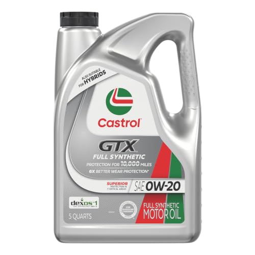
- 6X better wear protection on critical engine parts than...
- 1.3X better sludge protection than industry standards*
- 3X Stronger against viscosity breakdown than leading full...
- Protection for 10,000 miles between oil changes
- Meets or exceeds the following specifications: API SP/SN...

If the PDF is very large, it may not load in the preview below.
Some older TSBs had multiple PDFs — visit the NHTSA Website to view all PDFs.
If the TSB PDF does not show, download or view it on the NHTSA Website.
Click on the (+) Plus Sign
Then Click on Associated Document(s)
Search NHTSA Database for Recalls
Search NHTSA Database for Vehicle Investigations
View Latest Vehicle Investigations
Search NHTSA Database for Vehicle Complaints
View Latest Vehicle Complaints
TSB/Document ID: 23-NA-115
Replacement Service Bulletin Number:
MFR Communication Date: 2025-03-25
MFR Internal Campaign ID/Software Version:
Communication Type: Service Bulletin/Repair Instructions
NHTSA Components: ENGINE
MFR Component System:
MFR Component Subsystem:
Previous TSB | Next TSB |

- [Notice] When you receive a used device, it may be a customer return resold by Amazon without inspection. You can exchange it for a new one through Amazon. As this situation is unavoidable, we sincerely apologize. For any issues, contacting us via Amazon's "Messages" is the best way. THINKSCAN 689BT Bidirectional Scan Tool Can Be Used Immediately After It is Turned On, Without Complicated Registration Process, Which is More Convenient & Quick.
- Full Bi-Directional Control & 3000+ Active Tests: Take control and test components like actuators, fuel injectors, relays, and cooling fans in real time. You’ll quickly see if the problem is in the part itself or the control module — saving you hours of guesswork and frustrating trial-and-error.
- Advanced ECU Coding Capabilities: Handle module matching and hidden feature activation with confidence. When you replace an ECU or want to customize settings, this obd2 scanner diagnostic bi directional tool gives you the professional-level capabilities you need without the dealership price tag.
- 34+ Useful Reset and Maintenance Functions: Complete everyday service tasks smoothly with a wide range of helpful reset and maintenance functions. Whether you’re keeping up with regular upkeep or tackling a specific job, this scanner makes maintenance simpler and less stressful for both DIYers and pros.
- Comprehensive Full System Diagnostics: Diagnose every major system — Engine, Transmission, ABS, SRS, TPMS, and more — all in one place. Finally stop wondering if you’re missing something important; get the full picture and clear codes with ease.

- Top Reasons to Choose the D7S OBD2 Scanner: XTOOL D7S car scan tool, an upgrade of XTOOL D7, offers comprehensive features for automotive technicians, workshops, and DIY enthusiasts 1. Upgraded Hardware: 2+64GB memory, rear camera, intuitive interface, foldable bracket 2. Complete Diagnostics: FCA
 Autoauth, OE-level all system scan, 39+ maintenance services, 4K+ bidirectional, CANFD/DoIP protocol 3. Advanced Capabilities: ECU c0ding, PMI functions 4. Wide Compatibility: Support 10,000+ models, covering 99% vehicle brands 5. Multi-language: Available in 22+ languages, No IP Restrictions 6. 3-Year Updates: Save 300 bucks on software updates for the latest features and optimizations
 - 2026 Upgraded D7S Car Scanner Features: The newly 2026 D7S V2.0 scanner for car brings exciting features for advanced vehicle diagnostics and enhanced user experience 1. FCA AutoAuth: Now supports FCA SGW module for Chrysler, for Jeep, for Dodge (2018+), for Fiat (2017+), enabling faster vehicle communication without gateway restrictions 2. PMI (Offline ECU Pr0gramming): Allows for Ford, for Lincoln, and for Mazda ECU pr0gramming for new modules 3. Optimized Diagnostic Report 2.0: Personalized reports with logos and customer info for auto shops. Note: Compatibility varies by cars, please check before order
- 39+ Services/Resets/Adaptations/Relearns/Calibrations: XTOOL D7S full system car scanner diagnostic tool tackles 99% of common car issues through its 36+ special functions, including Oil Reset, EPB, SAS, BMS, Throttle Reset, Injector C0ding, ABS Bleed, TPMS Reset, Power Balance, etc and also covers specific-vehicle functions like Crank Sensor Relearn, ABS Initialization, Cylinder Power Balance, Fuel Trim Reset, Idle Relearn etc. This car diagnostic scanner enhances efficiency, making repairs and maintenance hassle-free. Tip: DO NOT for All vehicles, please check compatibility first
- Cost-effective ECU C0ding Scan Tool for Specific Brands: Enhance your vehicle's performance with XTOOL D7S! This obd2 scanner all systems bidirectional offers advanced capabilities at an affordable price, supports online for BMW, for Benz and offline for BENZ, for MIT, along with PMI functions for Ford, for Mazda, and for Lincoln. Ideal for technicians and DIY enthusiasts, this automotive scanner diagnostic tool optimizes vehicle performance and enhances the driving experience. Note: Not for all cars and modules, please send car VIN to check the compatibility before purchase
- OE All System Diagnostic & 8 Pids Graphing: XTOOL D7S is a comprehensive all system bi directional obd2 scanner that delivers dealer-level diagnostics, completely controlling over your vehicle’s performance and health. This automotive scan tool can read and clear DTCs, view live data and ECU information, retrieve freeze frames, and perform active tests and full obd2 functions. This bi-directional scan tool can can identify your vehicle's make, model, and year information with just one click and show up to 8 PIDs live data with options for CSV viewing, playback, and recording for in-depth analysis. It is easy-to-use for both professionals and beginners, helping pinpoint issues efficiently

- 【✅Compared to BOSSCOMM IF742, IF745 Offers Full-System Diagnostics】The BOSSCOMM IF745 car diagnostic scanner is an upgraded model of IF742. In addition to supporting all OBD2 Code Reader functions and 6 reset options (ABS/EPB/SAS/BMS/Oil/Throttle), it expands diagnostics from 4 systems (Check Engine/ABS/SRS/Transmission) to vehicle All systems, including Steering, Suspension, and Body Electronics. This provides deeper, more comprehensive diagnostic capabilities.
- 【✨10 OBD2 Functions】The BOSSCOMM IF745 scan tool’s DTC Lookup instantly translates fault codes into user-friendly explanations, its I/M Readiness feature streamlines emissions testing with a single tap, and Freeze Frame lets you pinpoint the exact moment of a fault for in-depth root-cause diagnosis. Combined with a live data dashboard and advanced diagnostics (O2S, OBMon, EVAP), it delivers comprehensive insights for confident troubleshooting.
- 【✨Deep Diagnostics for All Vehicle System Modules】Beyond code reading/clearing and ECU information retrieval, our all-in-one data stream feature lets you inspect all current fault codes and their locations across the vehicle’s systems. This vehicle code reader helps you turn off dashboard warning lights and perform a comprehensive self-check of your car at home—no more back-and-forth trips to the repair shop or hefty inspection fees.
- 【✨6 Essential Resets: ABS Bleeding, Oil, EPB, SAS, Throttle, BMS】The BOSSCOMM IF745 obd2 scanner diagnostic tool swiftly purges air from brake lines to restore braking sensitivity, fine-tunes maintenance cycles to eliminate false alerts, resolves parking brake issues with one-click control, recalibrates steering sensors for stability, optimizes engine idling/acceleration for smoother performance, and deeply resets battery systems to extend lifespan and range via precise parameter adjustments.❗NOTE: Does NOT support bidirectional control, coding, or programming.
- 【✨10,000+ Car Models, AutoVIN, 13 Languages】The BOSSCOMM IF745 vehicle scanner diagnostic tool covers 73+ global car brands and offers support in 13 languages, making it perfect for DIYers, auto mechanics, or as a thoughtful gift. With a single-click AutoVIN feature, it instantly retrieves vehicle serial numbers, streamlining diagnostics for users globally. This adaptable tool balances user-friendliness with precision, catering to both personal and professional requirements.✅Unsure about compatibility? Compatibility will vary on vehicles' model and year, pls reach us via 📧 [email protected] 📧 before purchase.
This product presentation was made with AAWP plugin.