
NHTSA ID Number: 11005662
Manufacturer Communication Number: TI-527
TSB/Document Date: 2024-08-05
Summary
Instructions for the Thule Omnistor 6300 Motor Kit 12V
THULE OMNISTOR 6300 xs
5 N
OUPPerT MOTOR KIT 12V INSTRUCTIONS a
=
AWNING
| | TT A ;
— >
NaN SE
as
’ °
Manufactured tor (WV LIPPERT
Lippert provides this and other Thule product manuals for download
from its website at https://support.Ici1.com/thule-awnings.
Asa supplier of a broad array of highly-engineered components in the recreation and transportation product markets, safety, education and customer satisfaction are
our primary concerns. Should you have any questions, please do not hesitate to contact us at 432-LIPPERT (432-547-7378) or by email at [email protected]
Self-help tips, technical documents, product videos and a training class schedule are available at lippert.com or by downloading the LippertNOW app.
Rev: 07.15.2024 Page 1 CCD-0008883
ga ee
Thule Omnistor 6300
Motor Kit 12V
> Instructions
VP 4p
@.
_ oh
se
Wa ee,
|
Ss
ey
\
1
eo -
“(BF
ae
Le
en _
oO - : A
2: \ =
Sr
, w=
| - ic
Sy a NU
oe) _ ae
2
Oo
zi
A - if © (\ ; =
aS
— 7
~ ELECTRICAL INSTALLATION
i
=
— =
i
——
eS ~ coe
\! —
OW\n 2 SE Sa
\
oO \ =
\ L
im ©6Cable usage
Max. 10m
S 2,5mm?
AWG 13
Min. cable Length |
< 10 mcable length > 10 m cable length
Max.10 m @_O aa +10m OO
~ Vy ~ 1
\ Ee, \ i J
MEA, \4E A ST ee
Sd) 1 \ |
Cc “Sen + SN |
\ ' I} a
AWG 13 \\ _ ao Zz ; =
2,5mm I - fen os Gry
a \ = 1
\ EY AWG 13 ~ il
Le 2,5mm? Xo
Wi
AWG 11- 4.0 mm?
AWG 13 - 2.5 mm? (Max. 12 m) AWG 13 - 2.5 mm?
(Max. 10 m) OM (Max. 4m)
ia sae tea se
6CA902-01 7
im ©6Control box
| DASHBOARD ' ' BATTERY 12V DC !
' toot
' '
| 12v—0~ ' '
1 = toot
' RELAY ! ' Fuse
1 u 87 ' 1 = C4 +O
1 = toot 20A
' 86 ) 2 [les ' '
! — feet
' toot
1 \
a
PAT Ty md aaa cd
Thule Awning Control Box for TO 6300 12V by tse
2x3 wotor not
connected
peste ae
xk Motor
sxx voto -
time out 5
Bx < OV &
O| fe 1/0
Perec pais) [4|[s]|6]|7| z
inn Anne
ll al Se | ps
1.5 mm? [Come
poeeee---------------] | |---400 -----] ---] ------------------
| SWITCH ! ' AWNING |
' 1 i)
x
G : i i og 8
| mi 8
i, toot
{ | ' § @O =
' ' 1 ( an
' e 5 ! ! SN i
' too
i i oo4
' tod
' too
a
5 6CA902-01
Eq Technical information
Read these instructions carefully. Warranty voided for incorrect connection
INSTALLATION OF THE ELECTRONIC CONTROL BOX
1. Install the control box inside the vehicle with screws.
2. Extend the motor wires (+ red & - black) to the control unit.
Also the connection to motor & controlbox should be made with @
2,5mm2 cables, tough to avoid loss of voltage due to the wires own
resistence, The installer might have to use up to @ 4mm2 wire in order to
bridge the distance between PCB & awning, while retaining a minimum of
9V at peak usage of 20A:
3. Connect the awning motor wires to the clamps 4 & 5 (See figure p. 7-8).
Connection wires: open the entrance by pushing gently with a screwdriver
in the rectangle beneath the correct connection. Then place the stripped
wire.
INSTALLATION OF THE SWITCH “AUTO / OPEN”
With this switch, the awning opens with one touch.
Note: the awning should only be opened when the key-contact of the
vehicle is turned off.
4. Install the switch (O40) on the desired location.
The switch should be monostable: (ON)-OFF-(ON) / (NC)-NO-(NC)
5. Connect the switch with entrance 1, 2 & 3 of the control box with 3 wires
of 2 1,5mm2.
CONNECTION OF THE BATTERY
It is recommended that the awning is connected to the secondary
battery of the vehicle, not the batter of the vehicle, in order to avoid all
disturbances from other appliances.
6. Place an electric cable 2 x @ 2,5mm2 from the control unit to the battery.
Place a 20A fuse in the + conduction. In order to avoid short-circuit:
do not insert the fuse until the electrical connection is completed.
7. Connect the battery to entrances 6 & 7 of the contro! box
6CA902-01 9
ATTENTION: The control unit will not operate if wrongly connected
Also the connection to motor & controlbox should be made with W
2,5mm2 cables, tough to avoid loss of voltage due to the wires own
resistence. The installer might have to use upto @ 4mm2 wire in order to
bridge the distance between PCB & awning. While retaining a minimum of
9V at peak usage of 20A
CONNECTION TO THE KEY CONTACT OF THE VEHICLE
Connect the battery to the PCB in such way that the awning cannot be
operated when the car-key is turned on.
8. Connect the chosen clamp with entrance 7 of the control box. Make sure
that the key contact is switched off before connecting.
FUNCTIONAL CHECK
Switch in OPEN-position
Check whether the awning does not open when the key contact and/or
motor from the vehicle is turned on.
SAFETY
When starting the vehicle, the awning should be closed.
Technische informatie
Lees deze voorschriften aandachtig. Bij verkeerde aansluiting vervalt elke
aanspraak op garantie.
AANSLUITING VAN DE SCHAKELKAST
1. Monteer de schakelkast binnen in het voertuig met schroeven.
2. Voer de draden van de TO luifel motor (+ rood en - zwart) naar de
schakelkast.
3. Sluit de draden van de motor aan op ingang 4 & 5 (Zie figuur p. 7-8).
Verbinding van de bedrading: open de toegang door met een
schroevendraaier licht te duwen in het vierkant onder de juiste ingang
Plaats daarna de gestripte electrische kabel.
10 6CA902-01
AANSLUITING VAN DE SCHAKELAAR “AUTOMATISCH / OPEN”
Met deze schakelaar opent de zonneluifel met één druk op de knop.
Opmerking: de zonneluifel mag enkel geopend worden wanneer het
contact van het voertuig uitgeschakeld is.
4. Monteer de schakelaar (040) op de gewenste plek. De schakelaar moet
monostabiel zijn: (ON) - OFF - CON) / (NC) - NO - (NC)
5. Verbind de schakelaar met ingang 1, 2 & 3 van de schakelkast met 3
draden van @ 1,5mm2.
AANSLUITING OP ACCU
Het is aangeraden om de zonneluifel te connecteren met de secundaire
batterij van het voertuig, niet de batterij van de motor, om storingen van
andere toestellen te vermijden
6. Leg een elektrische kabel 2 x @ 2,5mmz2 van de schakelkast naar de accu.
Beveilig de + leiding met een zekering van 20A. Om kortsluiting te
voorkomen: wacht met het plaatsen van de zekering tot na de volledige
elektrische aansluiting.
7. Sluit de accu aan op ingang 6 & 7 van de schakelkast.
OPGELET: Bij verkeerd aansluiten werkt de sturing niet. Voor de
verbinding van de motor & de schakelkast moet bedrading gebruikt
worden van @ 2,5mm2, om verlies van voltage door de eigen weerstand
van de bedrading te vermijden. De installateur moet mogelijks @ 4mm_2
bedrading gebruiken om de afstand van de PCB tot de zonneluifel te
overbruggen zonder verlies van voltage.
AANSLUITING MET DE CONTACTSLEUTEL VAN HET VOERTUIG
Verbind de batterij aan de PCB door middel van een relais
(zie aansluitschema) zodat de luifel niet kan gestuurd worden wanneer
het voertuig ingeschakeld is (sleutel contact aan).
8. Verbind de gekozen klem met ingang 7 van de schakelkast, zonder dat
het contact van het voertuig aan is.
6CA902-01 n
CONTROLE VAN DE WERKING
Schakelaar in OPEN-positie:
Controleer of de zonneluifel niet opent wanneer het contact en/of de
motor van het voertuig aan is.
VEILIGHEID
Wanneer het voertuig wordt gestart moet de luifel gesloten zijn.
Ea Technischen Informationen
Lesen Sie die Anleitung sorgfaltig durch, da der Garantieanspruch bei
unsachgemaBer Montage erlischt.
ANSCHLUSS DES SCHALTKASTENS
1. Montieren Sie den Schaltkasten im Inneren des Fahrzeugs mit Schrauben.
2. Fuhren Sie die Kabel von TO Markise (+ Rod und - Schwarz) zum
Schaltkasten.
3. SchlieBen Sie die Kabel des Motors an den Kiemmen 4 & 5 an (Figur p. 7-8).
Verbindung der Verkabelung Drucken Sie mit einem Schraubenzieher auf
das Rechteck unter der Kabeléffnung zum EinfUhren des Kabels.
Dann das Kabel mit abisoliertem Ende.
ANSCHLUSS DES SCHALTERS “AUTOMATISCH / OFFEN”
Dieser Schalter dffnet sich die Markise mit einem Knopfdruck.
ACHTUNG: die Markise kann nur gedffnet werden, wenn der Kontakt des
Fahrzeugs ausgeschaltet ist.
4. Montieren Sie den Schalter (@40) mit der roten Seite nach oben auf dem
gewunschten Ort. Der Schalter muss Monostabilen sein:
(ON) - OFF - (ON) / (NC) - NO - (NC)
5. Verbinden Sie den Schalter mit Eingang 1, 2 & 3 des Schalterkastens mit
3 x © 1,5mm2 Kabel.
12 6CA902-01
ANSCHLUSS DER BATTERIE
Es wird empfohlen, das die Markise mit der Sekundarbatterie des
Fahrzeugs, nicht die Batterie des Motors, verbunden zu werden. Damit die
elektronische Steuerung nicht von anderen Elektrogeraten gestdért wird.
6. Fuhren Sie ein elektrisches Kabel 2 x @ 2,5mm2 vom Schaltkasten zur
Batterie. FUhren Sie die + Leitung Uber eine 20A Sicherung. Um einen
Kurzschluss zu vermeiden, stecken Sie die Sicherung erst nach Vollendung
der Elektro-installation
7. SchlieBen Sie die Batterie an den Kiemmen 6 & 7 des Schaltkastens an.
ACHTUNG: Bei falscher Polung funktioniert der Schaltkasten nicht!
Fur den Anschluss des Motors und Schaltkasten muss ein elektrisches
Kabel @ 2,5mm2 benutzt werden, zum Verlust der Spannung durch den
eigenen Widerstand der Verkabelung verwendet werden.
Die installateur muss @ 4mm? elektrisches Kabel benutzen um den
abschtanz von den PCB Zu Markise zu Uberbrucken,
SICHERHEITSANSCHLUSS AM ZUNDSCHLOSS DES FAHRZEUGES
SchlieBen Sie den Akku auf der Platine auf solche Art und Weise, die die
Markise kann nicht bedient werden, wenn die Auto-Taste eingeschaltet ist.
KONTROLLE
Schalten in Stellung offen
Achten Sie darauf, dass die Markise nicht offnet, wenn das Kontakt und/
oder die motor von den Kraftfahrzeug funktioniert.
SICHERHEIT
Wenn das Fahrzeug gestartet werd sollte die Markise nicht gedffnet
werden.
6CA902-01 13
fa Information technique
Lisez ces notices attentivement. Un branchement fautif annule toutes les
clauses de garantie.
MONTAGE DU BOITIER ELECTRONIQUE
1. Installez le boitier électronique a proximité de la porte d’entrée avec des
vis
2. Branchez les fils du moteur (+ rouge et - noir) du Store au boitier
électronique.
3. Branchez les fils du moteur sur les fiches 4 & 5 (Voir Figure p. 7-8).
Connexion des cables: ouvrez l’accés en poussant légérement avec un
tournevis sur le carré en dessous du bon branchement. Branchez ensuite
le cable électrique.
BRANCHEMENT DE L’INTERRUPTEUR “AUTOMATIQUE / OUVERT”
Avec une seule touche sur l’interrupteur votre Strore s’ouvrira.
REMARQUE: Le Store peut uniquement étre ouvert lorsque le moteur de
votre véhicule est éteint.
4. Installez l’interrupteur (@40) a l’endroit souhaité
L’interrupteur doit étre monostable: (ON) - OFF - (ON) / (NC) - NO - (NC)
5. Branchez l’interrupteur sur le boitier électronique au portes: 1,2 & 3.
Utiliser trois cables de @ 1,5mm2.
RACCORDEMENT DE LA BATTERIE
ll est indispensable de branchez le Store sur la batterie secondaire du
vehicule, et non sur la batterie du moteur. Afin d’éviter toute interférence
causée par d’autres appareils électriques, a |’aide d’un relais.
6. Placez un cable électrique de 2 x @ 2,5mm2 du boitier électronique a la
batterie sécuriser. La conduite passera par un fusible de 20A. Afin d’éviter
un court-circuit, attendez d’introduire le fusible jusqu’a ce que apres que
le raccordement électrique soit fait complétement.
7. Branchez la batterie sur les fiches 6 & 7 du boitier électronique.
14 6CA902-01
ATTENTION: Dans le cas d’un branchement fautif, le boitier ne
fonctionnera pas. Pour le raccordement du moteur & du boitier
électronique il faut utiliser afin d’évitez toute des cables de @ 2,5mm2,
perte de tension par la résistance propre du cablage. L’installateur doit
semblablement utiliser des cables de @ 4mm2 pout couvrir la distance du
PCB jusqu’au Store.
RACCORDEMENT AVEC LA CLEF DE CONTACT DU VEHICULE
Branché le batterie sur le boitier électronique au moyen d’un relais
(Voir schéma de raccordement). Afin que le store ne peut pas étre envoyé
quand le contact du véhicule ou le moteur est allumé.
8. Branchez le fil de @ 2,5mm2 sur la fiche 7 du boitier électronique et cela
SANS que le contact du véhicule soit mis.
VERIFICATION
Interrupteur dans la position ouverte:
Assurez-vous que le Stor ne fonctionne pas lorsque le contact ou le
moteur du véhicule est allumé
SECURITE
Le Store doit étre fermé lorsque le véhicule démarre.
Informazioni tecniche
Leggere attentamente le presenti istruzioni. La garanzia decade in caso di
collegamento non corretto.
COLLEGAMENTO DELL’UNITA DI COMANDO
1. Installare l'unita di comando all’interno del veicolo servendosi di alcune
viti.
2. Collegare i fili del motore del frangisole TO (+ rosso e - nero) all’unita di
comando.
3. Collegare i fill del motore ai morsetti 4 e 5 (vedere la figura a p. 7-8).
6CA902-01 15
Collegamento dei fili: aprire l'ingresso spingendo delicatamente con
un cacciavite nel rettangolo al di sotto dell’ingresso corretto. Posizionare
successivamente il filo scamiciato.
INSTALLAZIONE DELL’INTERRUTTORE “AUTO / APERTO”
Grazie a questo interruttore il frangisole si apre con la semplice pressione
di un tasto.
Nota: il frangisole deve essere aperto solo a veicolo spento.
4. Installare l’interruttore (@ 40) nella posizione desiderata. L’interruttore
deve essere monostabile: (ON) - OFF - (ON) / (NC) - NO - (NC)
5. Collegare l'interruttore con gli ingressi 1, 2 e 3 dell’unita di comando
con 3 fili di 1,5mm2.
COLLEGAMENTO ALLA BATTERIA
Si raccomanda che il frangisole venga collegato alla batteria secondaria
del veicolo e non alla batteria del veicolo, in modo da evitare interferenze
da parte di altri dispositivi.
6. Collegare un cavo elettrico da 2 x 2,5mmz2 dall’unita di controllo alla
batteria. Proteggere la fase + con un fusibile da 20 A. Per evitare
cortocircuiti: non inserire il fusibile fino a quando il collegamento elettrico
non € completato.
7. Collegare la batteria agli ingressi 6 e 7 dell’unita di comando.
Attenzione: l’unita di comando non funzionera se collegata in modo errato.
|| collegamento al motore e all’unita di comando deve essere eseguito
utilizzando cavi di 2,5mm2, in modo da evitare perdita di tensione a
causa della resistenza dei fili. La tensione dell’alimentazione deve essere di
almeno 12V. Se a causa della lunghezza del cavo é troppo ampia la
tensione risultante scende al di sotto dei 9V in corrispondenza di un picco
di 20A, il motore pud spengersi.
Thule consiglia di utilizzare filo di rame di 4mm2 anziché di 2,5mm2
qualora la lunghezza del cavo superi i 10m.
COLLEGAMENTO ALLA CHIAVE DI ACCENSIONE DEL VEICOLO
Collegare la batteria al PCB mediante un relé (vedere lo schema di
collegamento) in modo che il frangisole non possa essere messo
16 6CA902-01
in funzione quando il veicolo € acceso (chiave di accensione inserita).
8. Collegare il morsetto scelto con l’ingresso 7 della scatola di comando,
accertandosi che il veicolo sia spento (chiave di accensione disinserita).
VERIFICA DEL FUNZIONAMENTO
Interruttore in posizione APERTO:
verificare che il frangisole non si apra quando il veicolo é acceso (chiave di
accensione inserita e/o motore acceso).
SICUREZZA
Quando si avwvia il veicolo, il frangisole deve essere chiuso.
Ej Teknisk information
Las dessa instruktioner noggrant. Garantin upphor vid felaktig anslutning.
INSTALLATION AV DEN ELEKTRONISKA STYRENHETEN
1. Installera styrenheten inne i fordonet med skruv.
2. Dra in motorledningarna (+ réd och - svart) till styrenheten. Anslutningen
till motor- och styrboxen ska ocksa géras med 2,5 mm2 kablar, kraftiga
nog fér att undvika férlust av spanning pa grund av tradens egen
resistans. Installatoren kan behOva anvanda upp till 4 mm? kabel i ordning
for att Overbrygga avstandet mellan PCB och markis, samtidigt som man
behaller minst 9 V vid maximal anvandning av 20A.
3. Anslut markisens motorledningar till klammorna 4 och 5 (se bild p. 7-8)
Anslutningskablar: Oppna ingangen genom att forsiktigt trycka med
en skruvmejsel i rektangeln nedanfor ratt anslutning. Placera sedan den
avfasade ledningen.
INSTALLATION AV BRYTAREN “AUTO / OPPEN”
Med denna brytare éppnas markisen med en knapptryckning.
OBS! Markisen bdr endast 6ppnas nar fordonets tandning ar avstangd.
6CA902-01 7
4. Montera brytaren (@ 40) pa Onskad plats. Vaxeln ska vara monostabil
(ON) -OFF- (ON) / (NC) -NO- (NC)
5. Anslut strémbrytaren med ingang 1,2 och 3 pa styrenheten med 3 tradar
pa 15 mm2
ANSLUTNING AV BATTERIET
Det rekommenderas att markisen ar ansluten till fordonets sekundara
batteri (bodels batteri) inte fordonets startbatteri, for att undvika storning
fran andra apparater.
6. Placera en kabel 2 x 2,5 mm2 fran styrenheten till batteriet. Satt en 20A
sakring pa + ledningen. Fér att undvika
kortslutning: satt inte in sdkringen tills den elektriska anslutningen ar
avslutad.
7. Anslut batteriet till ingangarna 6 och 7 pa styrenheten.
OBS: Styrenheten fungerar inte om den ar felaktigt ansluten. Aven
anslutningen till motor och styrenhet ska vara gjord med 2,5 mm2
kablar, tuffa for att undvika férlust av spanning pa grund av kabelns egen
resistans. Installatoren kan behOva anvanda upp till 4 mm2 kabel fér att
éverbrygga avstandet mellan PCB och markis. Medan man haller minst 9V
vid maximal anvandning 20A.
ANSLUTNING TILL FORDONETS TANDNING
Anslut batteriet till PCB pa sett sadant satt att markisen inte kan anvandas
nar tandningen ar paslagen.
8. Anslut den valda klamman med ingang 7 pa styrenheten. Kontrollera att
tandningen ar avstangd fore anslutning.
FUNKTION KONTROLL
Vaxla till OPEN-lage:
Kontrollera att markisen inte Oppnas nar tandningen eller motorn ar igang.
SAKERHET
Vid start av fordonet bor markisen vara stangd.
18 6CA902-01
fi Tekniset tiedot
Lue nama kayttdohjeet huolellisesti.
Takuu ei kata vaarda liitantaa.
SAHKOISEN OHJAINYKSIKON ASENNUS
1. Asenna ohjainyksikk6 ruuveilla ajoneuvon sisatiloihin.
2. Jatka moottorin johtoja (+ punainen & - musta) ohjainyksikdlle.
Liitannat moottorille & ohjainyksikdlle on tehtava @ 2,5mm2 johdoilla
jannitehavididen valttamiseksi kaapeleiden sisdisten vastusten
johdosta. Asentaja voi joutua kayttamaan 4mm 2 johtoa pitkilla
etaisyyksilla ohjainyksikOn ja markiisin valilla varmistamaan vahintaan
9 V jannite 20 A virralla.
3. Kytke moottorin johdot liittimiin 4 & 5 (katso kuva sivulla 7-8).
Johtimien liittaminen: avaa liitin painamalla varovasti ruuvimeisselilla
suorakulmioon oikean liittimen alapuolella. Laita kuorittu johto
liittimeen.
“AUTO / OPEN” KATKAISIJAN ASENNUS
Talla kytkimella markiisi aukeaa yhdella painalluksella
Huomio: markiisi saa aueta vain, kun ajoneuvon sytytysvirta ei ole
kytkettyna
4. Asenna katkaisija (@ 40 mm) sopivaan paikkaan.
Katkaisijan on oltava palautuva: (ON)-OFF-(ON) / (NC)-NO-(NC)
5. Liita katkaisija ohjainyksik6n liittimiin 1, 2 & 3 kolmella 1,5mm2 johdolla.
AKUN LIITTAMINEN
On suositeltavaa kytkea markiisi asunto-osan akkuun eika

- 💯【Conta.ct us for Support Directly】If you met any...
- 🔥🔥🔥【2026 AUTEL FLAGSHIP MK900BT MK900-BT, NEW...
- 🚗【3000+ ACTIVE TESTS (50➡3000+), SAME AS MS...
- 🚗【40+ HOT SERVICES FOR 150 MAKES (28+➡40+)】Full...
- 🚗【OE ALL SYSTEM DIAGNOSE, AUTO SCAN 2.0: SCAN LICENSE...

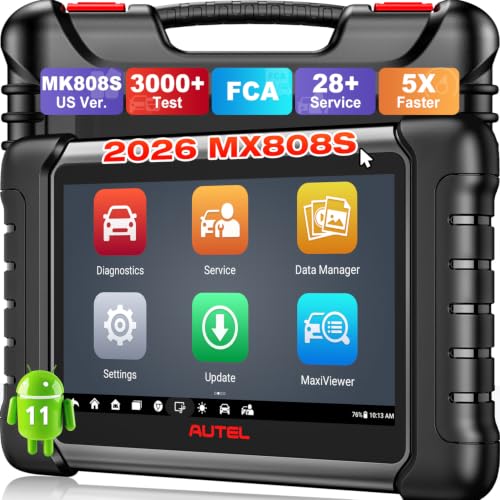
- 📌【We are Here for You】Dear valued customer, please be...
- 🚀【5X Faster Next-Level Hardware, Same as MK900/ MX...
- 🔥【3000+ Active Tests = MK900/MK900BT but...
- 📢【2026 U.S. Version, All-in-One as MK808S/ MK808Z...
- 🔥【28+ Hot Services for 150+ Brands】Same as MaxiCOM...
If the PDF is very large, it may not load in the preview below.
Some older TSBs had multiple PDFs — visit the NHTSA Website to view all PDFs.
If the TSB PDF does not show, download or view it on the NHTSA Website.
Click on the (+) Plus Sign
Then Click on Associated Document(s)
Search NHTSA Database for Recalls
Search NHTSA Database for Vehicle Investigations
View Latest Vehicle Investigations
Search NHTSA Database for Vehicle Complaints
View Latest Vehicle Complaints
TSB/Document ID: TI-527
Replacement Service Bulletin Number:
MFR Communication Date: 2024-07-15
MFR Internal Campaign ID/Software Version:
Communication Type: Service Bulletin/Repair Instructions
NHTSA Components: UNKNOWN OR OTHER
MFR Component System:
MFR Component Subsystem:
Previous TSB | Next TSB |

- [Notice] When you receive a used device, it may be a customer return resold by Amazon without inspection. You can exchange it for a new one through Amazon. As this situation is unavoidable, we sincerely apologize. For any issues, contacting us via Amazon's "Messages" is the best way. THINKSCAN 689BT Bidirectional Scan Tool Can Be Used Immediately After It is Turned On, Without Complicated Registration Process, Which is More Convenient & Quick.
- Full Bi-Directional Control & 3000+ Active Tests: Take control and test components like actuators, fuel injectors, relays, and cooling fans in real time. You’ll quickly see if the problem is in the part itself or the control module — saving you hours of guesswork and frustrating trial-and-error.
- Advanced ECU Coding Capabilities: Handle module matching and hidden feature activation with confidence. When you replace an ECU or want to customize settings, this obd2 scanner diagnostic bi directional tool gives you the professional-level capabilities you need without the dealership price tag.
- 34+ Useful Reset and Maintenance Functions: Complete everyday service tasks smoothly with a wide range of helpful reset and maintenance functions. Whether you’re keeping up with regular upkeep or tackling a specific job, this scanner makes maintenance simpler and less stressful for both DIYers and pros.
- Comprehensive Full System Diagnostics: Diagnose every major system — Engine, Transmission
 , ABS, SRS, TPMS, and more — all in one place. Finally stop wondering if you’re missing something important; get the full picture and clear codes with ease.

- Top Reasons to Choose the D7S OBD2 Scanner: XTOOL D7S car scan tool, an upgrade of XTOOL D7, offers comprehensive features for automotive technicians, workshops, and DIY enthusiasts 1. Upgraded Hardware: 2+64GB memory, rear camera, intuitive interface, foldable bracket 2. Complete Diagnostics: FCA Autoauth, OE-level all system scan, 39+ maintenance services, 4K+ bidirectional, CANFD/DoIP protocol 3. Advanced Capabilities: ECU coding, PMI functions 4. Wide Compatibility: Support 10,000+ models, covering 99% vehicle brands 5. Multi-language: Available in 22+ languages, No IP Restrictions 6. 3-Year Updates: Save 300 bucks on software updates for the latest features and optimizations
- 2026 Upgraded D7S Car Scanner Features: The newly 2026 D7S V2.0 scanner for car brings exciting features for advanced vehicle diagnostics and enhanced user experience 1. FCA AutoAuth: Now supports FCA SGW module for Chrysler, for Jeep, for Dodge (2018+), for Fiat (2017+), enabling faster vehicle communication without gateway restrictions 2. PMI (Offline ECU Programming): Allows for Ford, for Lincoln, and for Mazda ECU programming for new modules 3. Optimized Diagnostic Report 2.0: Personalized reports with logos and customer info for auto shops. Note: Compatibility varies by cars, please check before order
- Cost-effective ECU Coding Scan Tool for Specific Brands: Enhance your vehicle's performance with XTOOL D7S! This obd2 scanner all systems bidirectional offers advanced capabilities at an affordable price, supports online for BMW, for Benz and offline for BENZ, for MIT, along with PMI functions for Ford, for Mazda, and for Lincoln. Ideal for technicians and DIY enthusiasts, this automotive scanner diagnostic tool optimizes vehicle performance and enhances the driving experience. Note: Not for all cars and modules, please send car VIN to check the compatibility before purchase
- OE All System Diagnostic & 8 Pids Graphing: XTOOL D7S is a comprehensive all system bi directional obd2 scanner that delivers dealer-level diagnostics, completely controlling over your vehicle’s performance and health. This automotive scan tool can read and clear DTCs, view live data and ECU information, retrieve freeze frames, and perform active tests and full obd2 functions. This bi-directional scan tool can can identify your vehicle's make, model, and year information with just one click and show up to 8 PIDs live data with options for CSV viewing, playback, and recording for in-depth analysis. It is easy-to-use for both professionals and beginners, helping pinpoint issues efficiently
- 3 Years Software Update, Value for Money: With 3 years of software updates and 22+ languages(no IP restrictions), XTOOL D7S auto scanner code scanner ensures ongoing compatibility for the latest car models and improved diagnostic functions. This all system vehicle diagnostic scanner comes with a 30-day return policy and a 24-month repair for dependable performance. XTOOL are dedicated to your satisfaction, so enjoy seamless support and lifetime expert assistance. Should you encounter any issues or concerns, don’t hesitate to reach out XTOOL. D7S with newest update with 22 languages freely transfer without authorization, check details from setting-language or from XTOOL

- 【✅Compared to BOSSCOMM IF742, IF745 Offers Full-System Diagnostics】The BOSSCOMM IF745 car diagnostic scanner is an upgraded model of IF742. In addition to supporting all OBD2 Code Reader functions and 6 reset options (ABS/EPB/SAS/BMS/Oil/Throttle), it expands diagnostics from 4 systems (Check Engine/ABS/SRS/Transmission) to vehicle All systems, including Steering, Suspension, and Body Electronics. This provides deeper, more comprehensive diagnostic capabilities.
- 【✨6 Essential Resets: ABS Bleeding, Oil, EPB, SAS, Throttle, BMS】The BOSSCOMM IF745 obd2 scanner diagnostic tool swiftly purges air from brake lines to restore braking sensitivity, fine-tunes maintenance cycles to eliminate false alerts, resolves parking brake issues with one-click control, recalibrates steering sensors for stability, optimizes engine idling/acceleration for smoother performance, and deeply resets battery systems to extend lifespan and range via precise parameter adjustments.❗NOTE: Does NOT support bidirectional control, coding, or programming.
- 【✨Deep Diagnostics for All Vehicle System Modules】Beyond code reading/clearing and ECU information retrieval, our all-in-one data stream feature lets you inspect all current fault codes and their locations across the vehicle’s systems. This vehicle code reader helps you turn off dashboard warning lights and perform a comprehensive self-check of your car at home—no more back-and-forth trips to the repair shop or hefty inspection fees.
- 【✨10 OBD2 Functions】The BOSSCOMM IF745 scan tool’s DTC Lookup instantly translates fault codes into user-friendly explanations, its I/M Readiness feature streamlines emissions testing with a single tap, and Freeze Frame lets you pinpoint the exact moment of a fault for in-depth root-cause diagnosis. Combined with a live data dashboard and advanced diagnostics (O2S, OBMon, EVAP), it delivers comprehensive insights for confident troubleshooting.
- 【✨10,000+ Car Models, AutoVIN, 13 Languages】The BOSSCOMM IF745 vehicle scanner diagnostic tool covers 73+ global car brands and offers support in 13 languages, making it perfect for DIYers, auto mechanics, or as a thoughtful gift. With a single-click AutoVIN feature, it instantly retrieves vehicle serial numbers, streamlining diagnostics for users globally. This adaptable tool balances user-friendliness with precision, catering to both personal and professional requirements.✅Unsure about compatibility? Compatibility will vary on vehicles' model and year, pls reach us via 📧 [email protected] 📧 before purchase.
This product presentation was made with AAWP plugin.