
NHTSA ID Number: 10245772
Manufacturer Communication Number: 120310003
TSB/Document Date: 2023-12-04
Summary
Diagnostic Tips for Difficult to Resolve Tire/Wheel Vibration Concerns
File in Section:
Bulletin No.:
Service Bulletin
Date:
03 - Suspension
12-03-10-003
December, 2012
INFORMATION
Subject:
Diagnostic Tips for Difficult to Resolve Tire/Wheel Vibration Concerns
Models:
2007-2013 Cadillac Escalade Models
2007-2013 Chevrolet Avalanche, Silverado, Suburban, Tahoe
2007-2013 GMC Sierra, Yukon Models
Attention: The completed worksheets, within this bulletin, must be attached to the hard copy of
the repair order.
Some customers may comment on a vibration felt in the
steering wheel, seat or floorboard of the vehicle.
Early attempts at resolving this issue may have been
unsuccessful and this bulletin focuses on work required
beyond basic balancing.
The tire/wheel assembly may be out of balance, out of
specification for radial force variation, out of
specification for run-out and/or damaged.
Important:
• Before measuring tires on GM approved tire force
variation measurement equipment, the vehicle
MUST be driven a minimum of 24 km (15 mi) to
ensure removal of any flat-spotting. Refer to the
latest version of Corporate Bulletin
Number 03-03-10-007: Tire/Wheel Characteristics
of GM Original Equipment Tires.
• GM approved tire force variation measurement
equipment MUST be calibrated prior to measuring
tire/wheel assemblies for each vehicle.
• When re-mounting the tires to the wheels, a paste
type lubricant should be used to assure proper
wheel flange to tire bead alignment. Conversely,
when a match mounting procedure is complete,
care should be taken to assure wheels do not slip
on the rim when the vehicle is driven. For
complete information and guidelines on tire
lubricants, refer to the latest version of Corporate
Bulletin Number 12-03-10-001.
• When performing a wheel centering check, the
use of collet adapters and/or precision alignment
adapters may be useful.
Diagnostic Analysis
1. Gather details from the customer describing
exactly the condition they are experiencing.
2. Visually inspect the vehicle for issues that could
contribute to vibration.
3. Test drive the vehicle using the EVA tool. Also
measure the on vehicle run-out.
Copyright 2012 General Motors LLC. All Rights Reserved.
4. Check tire radial force variation, balance and
run-out using GM approved equipment such as the
Hunter GSP9700 or Snap-On RFV 2000.
5. Check hub-centering.
6. Verify that the condition has been corrected.
7. If vibration is still not at acceptable levels and
road-force numbers are within specifications,
contact TAC with the completed worksheets from
this bulletin.
The individual sections below will guide you through
this process.
1) Gather Detailed Information
Discuss the issue with the customer and ask specific
questions about the vibration concern. The latest
version of Corporate Bulletin Number 01-00-89-010 has
Customer Concern Verification Worksheets that are a
good starting point. For example:
• Speed condition is noticed.
• Does the vibration occur at a constant speed,
during acceleration, braking or coasting?
• Where is the vibration felt?
• Is the vibration intermittent?
• When did the vibration start?
• Is there any related history (alignment, new tires
or wheels, tire rotation, accidents, extreme
usage).
2) Visually inspect Tires and Wheels
Inspect for evidence of the following:
• Proper tire size and type, including if the tires are
original equipment
• Missing balance weights
• Verify tire pressures
• Damaged wheel
• Damaged tire
• Lug nut torque
• Tire or tire wear irregularities
Page 2
•
•
December, 2012
Mud/ice or other material build-up in the wheel
Any modifications to wheels, suspension or other
components that could be related, including
verification that the factory tires and wheels are
installed.
3) Test Drive Vehicle
A. Using EVA and Recording Results
Inspect for evidence of the following:
• Using the Electronic Vibration Analysis (EVA) tool,
determine the magnitude and frequency of the
vibration concern. Record this information on the
Tire/Wheel And Propshaft Rotation (Reference
Document #1) and the Vibration Analysis
Worksheet (Reference Document #2).
Basic EVA set up example:
• As an example, setting up the EVA can be done
by manually inputting the tire.
• EVA set up summary (see operating manual for
details). Select the following options and input
data as appropriate:
2.1. Auto Mode
2.2. Vehicle Speed
2.3. Manual Entry
2.4. Tire Width
2.5. Aspect ratio
2.6. Rim
2.7. RWD
2.8. MPH
2.9. Speed
2.10. Speed increment 5 mph
2.11. Press enter 3 times to get the vehicle
vibration readings and be sure to use the
arrow keys to change the speed
• Plan on a 24-32 km (15-20 mi) test drive to ensure
that the tires are warmed up, or have the customer
bring the vehicle in and immediately take it for a
test drive. If additional diagnostics are needed, be
sure to lift the vehicle immediately after the drive
(to minimize flat spotting).
• Identify where the vibration is felt.
• Verify the speed of the vibration and measure the
frequency and magnitude.
Important: When using the EVA Vibration Analyzer, or
any other comparable vibration analyzer (MTS 4100),
typical magnitudes of vibration, causing a customer
complaint for first order wheel, are generally above
0.012 mg. Vibration magnitudes below 0.012 mg are
generally within an acceptable range.
• While the EVA should be used for identifying the
source of the vibration, below are some
characteristics that may help:
• A vibration that gets worse as speed increases
may be balance related.
• Move the EVA sensor to different corners to
assist in determining the highest input to the
vibration concern.
• A vibration that occurs at only one speed may
be run-out related.
Bulletin No.: 12-03-10-003
• A vibration that phases in and out indicates a
condition at more than one source and/or 2nd
or higher order vibration.
• Low speed wobble is most likely run-out
related – not a balance problem.
• A vibration that occurs when accelerating or
decelerating is probably driveline component
related.
• If a vibration concern is identified, and is
related to the tire and wheel assembly, perform
the next steps. If it is not related to tire wheel
assembly, please refer to SI for appropriate
vibration diagnostics.
B. Measuring On-Vehicle Run-out
With a focus on the corner that has the highest input to
the customer’s concern:
1. Raise and support the vehicle.
176957
2. Wrap the circumference of each tire with tape (1) in
the center tread area. Wrapping the tread with tape
allows for a smooth and accurate reading of radial
run-out to be obtained.
Important: The dial indicator should be securely
clamped in order to obtain accurate readings.
3. Position the dial indicator on the taped portion of
the tire tread so that the dial indicator is
perpendicular to the tire tread surface.
4. Slowly rotate the tire and wheel assembly one
complete revolution in order to find the low spot.
5. Set the dial indicator to zero at the low spot.
6. Slowly rotate the tire and wheel assembly one
more complete revolution and measure the total
amount of radial run-out, marking the high point on
the tire and wheel assembly ignoring small
imperfections on the tire or tape.
Important: Before and after run-out measurements
must be recorded on the repair order for each tire and
wheel assembly that is balanced and/or
match-mounted.
Bulletin No.: 12-03-10-003
December, 2012
Note: Current specifications for maximum tire and
wheel assembly radial run-out - measured
on-vehicle: 1.52 mm (0.060 in). Verify the current
specification within SI.
176958
7. For measuring lateral run-out, position the dial
indicator on a smooth portion of the tire sidewall,
as close to the tread as possible, so that the dial
indicator is perpendicular to the tire sidewall
surface.
8. Slowly rotate the tire and wheel assembly one
complete revolution in order to find the low spot.
Ignore any jumps or dips due to sidewall splices.
9. Set the dial indicator to zero at the low spot.
10. Slowly rotate the tire and wheel assembly one
more complete revolution and measure the total
amount of lateral run-out. Ignore any jumps or dips
due to sidewall splices and attain an average
run-out measurement.
Notice: Maximum tire and wheel assembly lateral
run-out - measured on-vehicle: 1.52 mm (0.060 in).
11. Repeat steps 3 through 10 until all of the tire and
wheel assembly radial and lateral run-out
measurements have been taken.
12. If excessive run-out is identified, refer to Section 5
of this document, Tire RFV, Balance and Run-out,
Measurement below for details and replace the tire
or wheel assembly as needed.
4) Tire Radial Force Variation, Balance
and Run-out
Important: GM approved equipment such as the
Hunter GSP9700 or Snap-On RFv 2000 must be used
to verify proper tire radial force vibration.
Tire radial force vibration (RFV) can be defined as the
amount of stiffness variation the tire will produce in one
revolution under a constant load. Radial force variation
is what the vehicle feels because the load (weight) of
the vehicle is always on the tires. Although free run-out
Page 3
of tires (not under load) is not always a good indicator
of a smooth ride, it is critical that total tire/wheel
assembly run-out be within specification.
GM approved equipment such as the Hunter GSP9700
or Snap-On RFV 2000 loads the tire, similar to on the
vehicle, and measures radial force variation of the tire/
wheel assembly. Note that the wheel is affecting the
tire's RFV measurement at this point. To isolate the
wheel, its run-out must be measured. This can be
easily done on the Hunter, without the need to set up
dial indicators. If the wheel meets the run-out
specification, the tire's RFV can then be addressed.
1. Set the tire pressure to the placard values.
2. Using the Hunter GSP9700 or Snap-On RFV 2000,
check the balance of the tire/wheel assembly and
make corrections as necessary.
3. Measure radial force variation and radial run-out.
4. Make corrections to out of specification RFV and
run-out by Tire-to-Wheel Match-Mounting (refer to
Document ID: 2084548).
5. Record your measurements before and after on
the Balance Summary (Reference Document #3)
at the end of this bulletin. It may be of benefit to
have the lowest RFV assembly to the front left
corner. Re-check on the EVA and if the problem
still exists, test another vehicle to find tire(s) that do
not exhibit the same frequency and swap those
tires onto the subject vehicle (prior to installation,
RFV should be checked on the test vehicle tire
assemblies).
6. Mark the high point of the tire/wheel assembly to
assist with match mounting the assembly to
the hub.
Important: After balancing the tire/wheel assemblies,
make sure to make a mark on the tire where the valve
stem is located. This is to verify that there is no tire slip
occurring on the vehicle.
P-Metric tires of passenger cars
18 lbs (8 kg) or less
P-Metric tires on light trucks
24 lbs (11 kg) or less
LT-tires on light trucks
35 lbs (16 kg) or less
If match mounting tires to in-spec wheels produces
assembly values higher than these, tire replacement
may be necessary. Replacing tires at lower values will
probably mean good tires are being condemned.
Because tires can sometimes become temporarily
flat-spotted, which will affect force variation, it is
important that the vehicle be driven at least 26 km
(15 mi) prior to measuring. Tire pressure must also be
adjusted to the usage pressure on the vehicle's tire
placard prior to measuring.
Most Trucks will tolerate radial force variation up to
these levels. However, some trucks are more sensitive,
and may require lower levels. Also, there are other tire
parameters that equipment such as the Hunter
GSP9700 or Snap-On RFV 2000 cannot measure that
may be a factor.
Page 4
December, 2012
Important:
• When mounting a GM wheel to a wheel balancer/
force variation machine, always use the wheel's
center pilot hole. This is the primary centering
mechanism on all GM wheels; the bolt holes are
secondary. Usually a back cone method to the
machine should be used. For added accuracy and
repeatability, a flange plate should be used to
clamp the wheel onto the cone and machine. This
system is offered by all balancer manufacturers in
GM's dealer program.
• The use of “Quick Match” should be avoided when
using the Hunter GSP9700 and a centering check
must be performed on each wheel.
• Any type of service equipment that removes tread
rubber by grinding, buffing or truing is NOT
recommended, and may void the tire warranty.
However, tires may have been ground by the tire
company as part of their tire manufacturing
process. This is a legitimate procedure.
5) Check for Proper Hub-Centering
•
After verifying RFV, run-out and balance are within
specifications, remount the tire/wheel assembly to
the vehicle.
3218163
1.1. Remove the wheel center caps.
1.2. While the wheels are mounted to the vehicle,
use a feeler gauge to measure the gap
between the wheel center and axle hub.
1.3. Perform this task near each stud around
each axle hub.
1.4. If the gaps from the six measurements on
each hub vary more than 0.002”, loosen the
lug nuts.
1.5. Re-center the wheel on the hub, trying to
make sure there is an even gap all around
the axle hub.
1.6. Torque the lug nuts in small increments to
prevent hub-shift.
Bulletin No.: 12-03-10-003
6) Verify Correction
Drive the truck and evaluate at speeds as defined by
the customer and previously proven during your test
drive.
7) Contact TAC
If the Customer Concern still exists and all of the
measurements are in specification, contact the
Technical Assistance Center (TAC) with completed
worksheets.
Bulletin No.: 12-03-10-003
December, 2012
Page 5
Reference Document #1
3218154
Page 6
December, 2012
Bulletin No.: 12-03-10-003
Reference Document #2
Steering Wheel Shake Worksheet
To:
Dealer:
Fax Number:
VIN__ __ __ __ __ __ __ __ __ __ __ __ __ __ __ __ __
Procedure Performed By:
Date:
Model:
Year:
Odometer:
VIN __ __ __ __ __ __ __ __ __ __ __ __ __ __ __ __ __
TAC Case #, if applicable:
Conditions During Road Test Procedures
As condition occurs: Engine RPM_____________
Vehicle Speed__________________
Vibration/Noise detected during the following road test procedures:
Engine RPM_______________ Vehicle Speed_______________
Slow Acceleration Test: Yes__________ No__________
Neutral Coast-Down Test: Yes__________ No__________
Downshift Test: Yes__________ No__________
Neutral Run-Up Test: Yes__________ No__________
Steering Input Test: Yes__________ No__________
When using the EVA, always take a snapshot. This will help determine which vibration shows up the most.
Important: Vibrate software can also be used to assist in vibration diagnosis. Refer to Vibrate Software Description and
Operation in SI.
EVA Readings
Refer to Electronic Vibration Analyzer (EVA) Description and Operation in SI for more detailed information.
Important: As a reminder, place the EVA sensor where the vibration is mostly felt. Ensure the word “UP” on the sensor is
physically facing up. The typical areas are the seat track, the steering column or the instrument panel. Locating the EVA sensor
on additional area (i.e. the right fender, left fender, right quarter panel, left quarter panel, rear seat track, etc.) may also assist in
determining the component causing the vibration/noise. The key is to look for the same Hz reading with the greatest amplitude G
readings.
Bulletin No.: 12-03-10-003
December, 2012
Steering Wheel Shake Worksheet
FILL OUT ONLY THE APPLICABLE PORTION OF THE WORKSHEET THAT APPLIES TO THE VIBRATION/NOISE:
Sensor at Steering Column:
1st Line MPH/KPH:__________ HZ:__________ Gs:__________
2nd Line MPH/KPH:__________ HZ:__________ Gs:__________
Sensor at Roof:
1st Line MPH/KPH:__________ HZ:__________ Gs:__________
2nd Line MPH/KPH:__________ HZ:__________ Gs:__________
Sensor at Passenger Seat Rail:
1st Line MPH/KPH:__________ HZ:__________ Gs:__________
2nd Line MPH/KPH:__________ HZ:__________ Gs:__________
Tire Size and Brand:_____________________________________
Wheel/Tire Runouts on vehicle (max. 0.050 in (1.27 mm))
Refer to Corporate Bulletin Number 00-03-10-006D for tire radial force variation.
Right rear: Inner lateral:__________ Center radial:__________
Left rear: Inner lateral:__________ Center radial:__________
Right front: Inner lateral:__________ Center radial:__________
Left front: Inner lateral:__________ Center radial:__________
Mounting surface runouts (max. 0.005 in (0.127 mm))
Flange, right rear:__________ Hub, right front:__________
Flange, left rear:__________ Hub, left front:__________
Wheel stud runouts (max. 0.008 in (0.203 mm))
Flange, right rear:__________ Hub, right front:__________
Flange, left rear:__________ Hub, left front:__________
List Additional Repairs, If Applicable
Page 7
Page 8
December, 2012
Bulletin No.: 12-03-10-003
Reference Document #3
3218151
GM bulletins are intended for use by professional technicians, NOT a "do-it-yourselfer". They are written to inform these
technicians of conditions that may occur on some vehicles, or to provide information that could assist in the proper
service of a vehicle. Properly trained technicians have the equipment, tools, safety instructions, and know-how to do a
job properly and safely. If a condition is described, DO NOT assume that the bulletin applies to your vehicle, or that your
vehicle will have that condition. See your GM dealer for information on whether your vehicle may benefit from the
information.
WE SUPPORT VOLUNTARY
TECHNICIAN
CERTIFICATION
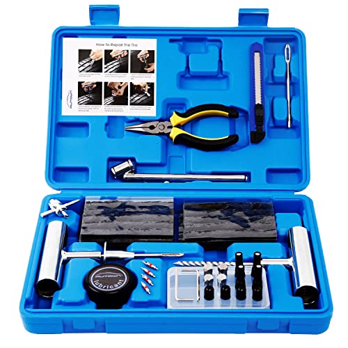
- [🔨PROFESSIONAL QUALITY ] - AUTOWN Tire Repair Kits are...
- [🔨DURABLE & SAFE ] - The tire puncture repair set own...
- [🔨MULTIPLE USES ] - The AUTOWN 68 pcs tire repair heavy...
- [🔨EASY TO USE ] - Our tire plug kits have everything you...
- [🔨QUICK ACTION] - We care about every customer's sense of...
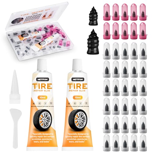
- 【Perfect Emergency Repair Solution】This kit includes...
- 【Premium Materials for Safe Repairs】Our tire screw plugs...
- 【2 Sizes for Every Puncture】Choose the right size for...
- 【5-Minute DIY Repair】Skip the auto shop and fix flats...
- 【Emergency-Ready Design】Compact & ready for...
If the PDF is very large, it may not load in the preview below.
Some older TSBs had multiple PDFs — visit the NHTSA Website to view all PDFs.
If the TSB PDF does not show, download or view it on the NHTSA Website.
Click on the (+) Plus Sign
Then Click on Associated Document(s)
Search NHTSA Database for Recalls
Search NHTSA Database for Vehicle Investigations
View Latest Vehicle Investigations
Search NHTSA Database for Vehicle Complaints
View Latest Vehicle Complaints
TSB/Document ID: 120310003
Replacement Service Bulletin Number:
MFR Communication Date: 2012-12-01
MFR Internal Campaign ID/Software Version:
Communication Type: Service Bulletin/Repair Instructions
NHTSA Components: UNKNOWN OR OTHER
MFR Component System:
MFR Component Subsystem:
Previous TSB | Next TSB |

- [Notice] When you receive a used device, it may be a customer return resold by Amazon without inspection. You can exchange it for a new one through Amazon. As this situation is unavoidable, we sincerely apologize. For any issues, contacting us via Amazon's "Messages" is the best way. THINKSCAN 689BT Bidirectional Scan Tool Can Be Used Immediately After It is Turned On, Without Complicated Registration Process, Which is More Convenient & Quick.
- Full Bi-Directional Control & 3000+ Active Tests: Take control and test components like actuators, fuel injectors, relays, and cooling fans in real time. You’ll quickly see if the problem is in the part itself or the control module — saving you hours of guesswork and frustrating trial-and-error.
- Advanced ECU Coding Capabilities: Handle module matching and hidden feature activation with confidence. When you replace an ECU or want to customize settings, this obd2 scanner diagnostic bi directional tool gives you the professional-level capabilities you need without the dealership price tag.
- 34+ Useful Reset and Maintenance Functions: Complete everyday service tasks smoothly with a wide range of helpful reset and maintenance functions. Whether you’re keeping up with regular upkeep or tackling a specific job, this scanner makes maintenance simpler and less stressful for both DIYers and pros.
- Comprehensive Full System Diagnostics: Diagnose every major system — Engine, Transmission, ABS, SRS, TPMS, and more — all in one place. Finally stop wondering if you’re missing something important; get the full picture and clear codes with ease.

- Top Reasons to Choose the D7S OBD2 Scanner: XTOOL D7S car scan tool, an upgrade of XTOOL D7, offers comprehensive features for automotive technicians, workshops, and DIY enthusiasts 1. Upgraded Hardware: 2+64GB memory, rear camera, intuitive interface, foldable bracket 2. Complete Diagnostics: FCA
 Autoauth, OE-level all system scan, 39+ maintenance services, 4K+ bidirectional, CANFD/DoIP protocol 3. Advanced Capabilities: ECU c0ding, PMI functions 4. Wide Compatibility: Support 10,000+ models, covering 99% vehicle brands 5. Multi-language: Available in 22+ languages, No IP Restrictions 6. 3-Year Updates: Save 300 bucks on software updates for the latest features and optimizations
 - 2026 Upgraded D7S Car Scanner Features: The newly 2026 D7S V2.0 scanner for car brings exciting features for advanced vehicle diagnostics and enhanced user experience 1. FCA AutoAuth: Now supports FCA SGW module for Chrysler, for Jeep, for Dodge (2018+), for Fiat (2017+), enabling faster vehicle communication without gateway restrictions 2. PMI (Offline ECU Pr0gramming): Allows for Ford, for Lincoln, and for Mazda ECU pr0gramming for new modules 3. Optimized Diagnostic Report 2.0: Personalized reports with logos and customer info for auto shops. Note: Compatibility varies by cars, please check before order
- 39+ Services/Resets/Adaptations/Relearns/Calibrations: XTOOL D7S full system car scanner diagnostic tool tackles 99% of common car issues through its 36+ special functions, including Oil Reset, EPB, SAS, BMS, Throttle Reset, Injector C0ding, ABS Bleed, TPMS Reset, Power Balance, etc and also covers specific-vehicle functions like Crank Sensor Relearn, ABS Initialization, Cylinder Power Balance, Fuel Trim Reset, Idle Relearn etc. This car diagnostic scanner enhances efficiency, making repairs and maintenance hassle-free. Tip: DO NOT for All vehicles, please check compatibility first
- Cost-effective ECU C0ding Scan Tool for Specific Brands: Enhance your vehicle's performance with XTOOL D7S! This obd2 scanner all systems bidirectional offers advanced capabilities at an affordable price, supports online for BMW, for Benz and offline for BENZ, for MIT, along with PMI functions for Ford, for Mazda, and for Lincoln. Ideal for technicians and DIY enthusiasts, this automotive scanner diagnostic tool optimizes vehicle performance and enhances the driving experience. Note: Not for all cars and modules, please send car VIN to check the compatibility before purchase
- OE All System Diagnostic & 8 Pids Graphing: XTOOL D7S is a comprehensive all system bi directional obd2 scanner that delivers dealer-level diagnostics, completely controlling over your vehicle’s performance and health. This automotive scan tool can read and clear DTCs, view live data and ECU information, retrieve freeze frames, and perform active tests and full obd2 functions. This bi-directional scan tool can can identify your vehicle's make, model, and year information with just one click and show up to 8 PIDs live data with options for CSV viewing, playback, and recording for in-depth analysis. It is easy-to-use for both professionals and beginners, helping pinpoint issues efficiently

- 【✅Compared to BOSSCOMM IF742, IF745 Offers Full-System Diagnostics】The BOSSCOMM IF745 car diagnostic scanner is an upgraded model of IF742. In addition to supporting all OBD2 Code Reader functions and 6 reset options (ABS/EPB/SAS/BMS/Oil/Throttle), it expands diagnostics from 4 systems (Check Engine/ABS/SRS/Transmission) to vehicle All systems, including Steering, Suspension, and Body Electronics. This provides deeper, more comprehensive diagnostic capabilities.
- 【✨10 OBD2 Functions】The BOSSCOMM IF745 scan tool’s DTC Lookup instantly translates fault codes into user-friendly explanations, its I/M Readiness feature streamlines emissions testing with a single tap, and Freeze Frame lets you pinpoint the exact moment of a fault for in-depth root-cause diagnosis. Combined with a live data dashboard and advanced diagnostics (O2S, OBMon, EVAP), it delivers comprehensive insights for confident troubleshooting.
- 【✨Deep Diagnostics for All Vehicle System Modules】Beyond code reading/clearing and ECU information retrieval, our all-in-one data stream feature lets you inspect all current fault codes and their locations across the vehicle’s systems. This vehicle code reader helps you turn off dashboard warning lights and perform a comprehensive self-check of your car at home—no more back-and-forth trips to the repair shop or hefty inspection fees.
- 【✨6 Essential Resets: ABS Bleeding, Oil, EPB, SAS, Throttle, BMS】The BOSSCOMM IF745 obd2 scanner diagnostic tool swiftly purges air from brake lines to restore braking sensitivity, fine-tunes maintenance cycles to eliminate false alerts, resolves parking brake issues with one-click control, recalibrates steering sensors for stability, optimizes engine idling/acceleration for smoother performance, and deeply resets battery systems to extend lifespan and range via precise parameter adjustments.❗NOTE: Does NOT support bidirectional control, coding, or programming.
- 【✨10,000+ Car Models, AutoVIN, 13 Languages】The BOSSCOMM IF745 vehicle scanner diagnostic tool covers 73+ global car brands and offers support in 13 languages, making it perfect for DIYers, auto mechanics, or as a thoughtful gift. With a single-click AutoVIN feature, it instantly retrieves vehicle serial numbers, streamlining diagnostics for users globally. This adaptable tool balances user-friendliness with precision, catering to both personal and professional requirements.✅Unsure about compatibility? Compatibility will vary on vehicles' model and year, pls reach us via 📧 [email protected] 📧 before purchase.

This product presentation was made with AAWP plugin.