
NHTSA ID Number: 10238006
Manufacturer Communication Number: TB441203
TSB/Document Date: 2023-06-26
Summary
This Technical Bulletin provides an overview for performing vehicle four Wheel Alignment and information on improving vehicle pull/drift using selective tire placement. The information provided is based on the Hunter alignment equipment and the Hunter GSP9700 balancer with StraightTrak. The general information provided in the bulletin, such as alignment terminologies, warranty information and Vehicle drift/pull diagnosis is not dependent on the alignment equipment and still applies with the use of other alignment equipment.
Technical Bulletin
Model(s)
Year
Eng. Code
Trans. Code
VIN Range From
VIN Range To
Jetta Sedan
2011-2013
All
All
All
All
Passat, Beetle
2012-2013
All
All
All
All
Condition
44 12 03 November 02, 2012 2031087
Four Wheel Alignment Overview
This Technical Bulletin provides an overview for performing vehicle four Wheel Alignment and information on
improving vehicle pull/drift using selective tire placement. The information provided is based on the Hunter
alignment equipment and the Hunter GSP9700 balancer with StraightTrak. The general information provided in the
bulletin, such as alignment terminologies, warranty information and Vehicle drift/pull diagnosis is not dependent on
the alignment equipment and still applies with the use of other alignment equipment.
The following topics are addressed in this bulletin:
1. Alignment Terminologies
2. Toe adjustment –Steering Wheel Off Center (SWOC)
3. Camber adjustment
4. Caster measurement
5. Selective tire placement to improve vehicle pull/drift due to road crown.
6. Warranty
Technical Background
The information provided in this bulletin is intended to assist technicians in obtaining the correct alignment results
and maximize the use of the alignment and tire balancer equipment. Vehicle alignment should always be
performed base on the information published in the service manual.
Note:
A copy of the alignment before and after measurements must be filed with the Repair Order. If a Volkswagen
Technical Assistance (VTA) ticket was opened, the alignment before and after measurement should be attached
before the VTA is closed.
Production Solution
Not applicable.
Page 1 of 14
© 2012 Volkswagen Group of America, Inc.
All rights reserved. Information contained in this document is based on the latest information available at the time of printing and is subject to the copyright and other
intellectual property rights of Volkswagen Group of America, Inc., its affiliated companies and its licensors. All rights are reserved to make changes at any time without notice.
No part of this document may be reproduced, stored in a retrieval system, or transmitted in any form or by any means, electronic, mechanical, photocopying, recording, or
otherwise, nor may these materials be modified or reposted to other sites, without the prior expressed written permission of the publisher.
Technical Bulletin
Service
1. Alignment terminologies
TOE ‐ The amount the tires point inwards or
outwards when viewing the car from above.
Figure 1
Positive toe (red line) or Toe‐in: The tires
point inwards towards the center of the
vehicle.
Negative toe (blue line) or Toe‐out: The
tires point outwards away from the center of
the vehicle
Figure 1
CAMBER ‐ Angle between the vertical axis
of the wheel and the vertical axis of the
vehicle when viewed from the front or rear.
Positive (red line): The upper sidewall of the
tire is tilted outwards away from the center of
the vehicle.
Negative (blue line): The upper sidewall of
the tire is tilted towards the center of the
vehicle.
Figure 2
Page 2 of 14
© 2012 Volkswagen Group of America, Inc.
All rights reserved. Information contained in this document is based on the latest information available at the time of printing and is subject to the copyright and other
intellectual property rights of Volkswagen Group of America, Inc., its affiliated companies and its licensors. All rights are reserved to make changes at any time without notice.
No part of this document may be reproduced, stored in a retrieval system, or transmitted in any form or by any means, electronic, mechanical, photocopying, recording, or
otherwise, nor may these materials be modified or reposted to other sites, without the prior expressed written permission of the publisher.
Technical Bulletin
Figure 3
CASTER ‐ When viewing a car from the side, the angle of the vehicle’s steering axis is defined by drawing a line
through the upper and lower ball joints (for a double wishbone front suspension), or through the strut tower mount
and the lower ball joint.
Positive (red line): The line leans towards the rear of the car.
Negative (blue line): The line leans towards the front of the car.
Tip:
For additional information on wheel alignment see Self Study Program (SSP) 860103 – Wheel Alignment – Basics.
Page 3 of 14
© 2012 Volkswagen Group of America, Inc.
All rights reserved. Information contained in this document is based on the latest information available at the time of printing and is subject to the copyright and other
intellectual property rights of Volkswagen Group of America, Inc., its affiliated companies and its licensors. All rights are reserved to make changes at any time without notice.
No part of this document may be reproduced, stored in a retrieval system, or transmitted in any form or by any means, electronic, mechanical, photocopying, recording, or
otherwise, nor may these materials be modified or reposted to other sites, without the prior expressed written permission of the publisher.
Technical Bulletin
2. Toe adjustment – Steering Wheel Off Center (SWOC)
Front and rear toe adjustment procedures are located in the repair manual under, Repair Manual > Chassis >
Suspension, Wheel, Steering > 44 Wheels, Tires, Wheel Alignment > General Information.
When performing wheel alignment, the steering column must be adjusted to the center tilt position. This
is due to steering wheel off set of up to 1.2 degrees from center tilt position of the steering column to the
full up or the full down tilt position. See illustration 4 & 5 below.
Tip:
The tools shown in figure 4 & 5 were used to demonstrate the steering wheel off set. These are not dealer
required tools.
Steering wheel in the fully up tilt position
and off set to the right.
Figure 4
Steering wheel in the fully down tilt
position and off set to the left.
Figure 5
Page 4 of 14
© 2012 Volkswagen Group of America, Inc.
All rights reserved. Information contained in this document is based on the latest information available at the time of printing and is subject to the copyright and other
intellectual property rights of Volkswagen Group of America, Inc., its affiliated companies and its licensors. All rights are reserved to make changes at any time without notice.
No part of this document may be reproduced, stored in a retrieval system, or transmitted in any form or by any means, electronic, mechanical, photocopying, recording, or
otherwise, nor may these materials be modified or reposted to other sites, without the prior expressed written permission of the publisher.
Technical Bulletin
Tip:
For a video demonstration of steering wheel off set, go to: VWWebsource > Select your view: After sales > Quick
Tips > Quick Tips for Technicians > Chassis.
Note:
DO NOT remove the steering wheel from the steering column to correct steering wheel off center. If it has been
determined that the steering wheel is off center with the steering in the center tilt position, an alignment should be
performed and the toe adjusted to correct the steering position.
3. Camber adjustment
Camber adjustments should be made based on the information in the repair manual.
Note:
If the sub-frame bolts are loosened / removed to adjust camber, the bolts MUST be replaced with new
bolts. Sub-frame bolts are torque to yield and should never be re-used after they are loosened.
4. Caster Measurement
Caster is not an adjustable angle for the models addressed in this bulletin.
1. When performing alignment using the Hunter equipment, after the initial “Before” measurements are displayed,
additional steps are required to read the correct caster measurement. Without these additional steps, the
equipment may display caster measurements that are out of specification. Please follow the steps below to
obtain the correct caster measurements.
When the initial “Before” measurements
are displayed, scroll down to make
additional measurements.
Figure 6
Page 5 of 14
© 2012 Volkswagen Group of America, Inc.
All rights reserved. Information contained in this document is based on the latest information available at the time of printing and is subject to the copyright and other
intellectual property rights of Volkswagen Group of America, Inc., its affiliated companies and its licensors. All rights are reserved to make changes at any time without notice.
No part of this document may be reproduced, stored in a retrieval system, or transmitted in any form or by any means, electronic, mechanical, photocopying, recording, or
otherwise, nor may these materials be modified or reposted to other sites, without the prior expressed written permission of the publisher.
Technical Bulletin
Press K3 to select > Make Additional
Measurement.
Figure 7
Scroll down to select > Frame Angle >
Press K4 to select OK.
Figure 8
Page 6 of 14
© 2012 Volkswagen Group of America, Inc.
All rights reserved. Information contained in this document is based on the latest information available at the time of printing and is subject to the copyright and other
intellectual property rights of Volkswagen Group of America, Inc., its affiliated companies and its licensors. All rights are reserved to make changes at any time without notice.
No part of this document may be reproduced, stored in a retrieval system, or transmitted in any form or by any means, electronic, mechanical, photocopying, recording, or
otherwise, nor may these materials be modified or reposted to other sites, without the prior expressed written permission of the publisher.
Technical Bulletin
Measure the vehicle frame angle at the
door sills using a digital level
(accelerometer).
Tip:
The frame angle for the car in figure 9
measures 0.9°, where the rear is higher
than the front. The nominal frame angle
is 0.4° by design and must be
subtracted from the measured frame
angle.
For example 0.9° ‐ 0.4° = 0.5°
Figure 9
Enter the angles in the left and right
frame angle fields > press K4 to select
OK.
The caster measurement will now read
correct. Please note that cross caster
measurement will remain the same.
Figure 10
Tip:
If the tool to measure frame angle is not available, measure the vehicle ride height (Standing height), and if within
specification per the repair manual, enter 0.4° for the left and right frame angle.
Vehicle ride height and symmetry measurement/Set back are very important when diagnosing vehicle suspension
or drifting/pulling concerns. To include these measurement in the alignment summary select K3 > Make Additional
Measurement and scroll down to select these measurements.
Page 7 of 14
© 2012 Volkswagen Group of America, Inc.
All rights reserved. Information contained in this document is based on the latest information available at the time of printing and is subject to the copyright and other
intellectual property rights of Volkswagen Group of America, Inc., its affiliated companies and its licensors. All rights are reserved to make changes at any time without notice.
No part of this document may be reproduced, stored in a retrieval system, or transmitted in any form or by any means, electronic, mechanical, photocopying, recording, or
otherwise, nor may these materials be modified or reposted to other sites, without the prior expressed written permission of the publisher.
Technical Bulletin
Axle symmetry measurements/ set back are displayed in angles. For easier understanding it is best to have the
measurements displayed in distances. Follow the procedures below to measure axle symmetry and display the
measurements in distances.
After selecting “Make Additional
Measurements”, scroll down and select
> Symmetry Measurements/ Set Back >
Press K4 for OK.
Figure 11
Center the front wheels as shown on the
monitor. > Press K4 for Ready.
Figure 12
Page 8 of 14
© 2012 Volkswagen Group of America, Inc.
All rights reserved. Information contained in this document is based on the latest information available at the time of printing and is subject to the copyright and other
intellectual property rights of Volkswagen Group of America, Inc., its affiliated companies and its licensors. All rights are reserved to make changes at any time without notice.
No part of this document may be reproduced, stored in a retrieval system, or transmitted in any form or by any means, electronic, mechanical, photocopying, recording, or
otherwise, nor may these materials be modified or reposted to other sites, without the prior expressed written permission of the publisher.
Technical Bulletin
The axle symmetry/ set back will be
displayed in angles. To show angles as
Distances > Press K2.
Enter the Rim Width
16” = 6.5”
17” = 7”
18” = 8”
Figure 13
Ensure that the correct box is checked
depending on the type of wheel clamp
spade that is used > Press K4 for OK.
Figure 14
Page 9 of 14
© 2012 Volkswagen Group of America, Inc.
All rights reserved. Information contained in this document is based on the latest information available at the time of printing and is subject to the copyright and other
intellectual property rights of Volkswagen Group of America, Inc., its affiliated companies and its licensors. All rights are reserved to make changes at any time without notice.
No part of this document may be reproduced, stored in a retrieval system, or transmitted in any form or by any means, electronic, mechanical, photocopying, recording, or
otherwise, nor may these materials be modified or reposted to other sites, without the prior expressed written permission of the publisher.
Technical Bulletin
Steer the wheels straight ahead as
instructed > Press K4 for Ready.
Figure 15
Track and wheelbase screen is
displayed > Press K4 for OK.
Figure 16
Page 10 of 14
© 2012 Volkswagen Group of America, Inc.
All rights reserved. Information contained in this document is based on the latest information available at the time of printing and is subject to the copyright and other
intellectual property rights of Volkswagen Group of America, Inc., its affiliated companies and its licensors. All rights are reserved to make changes at any time without notice.
No part of this document may be reproduced, stored in a retrieval system, or transmitted in any form or by any means, electronic, mechanical, photocopying, recording, or
otherwise, nor may these materials be modified or reposted to other sites, without the prior expressed written permission of the publisher.
Technical Bulletin
The axle symmetry measurement/ set
back will now display in distances. Press
K3 to print the alignment summary page.
Figure 17
5. Selective tire placement to improve vehicle drift due to road crown
Vehicle pull/drift diagnosis
Note:
It is normal for a vehicle to drift to the right if the steering wheel is released while driving. Road crown will have the
most significant effect on the time it takes for a vehicle to drift out of its lane. Always test drive the vehicle to
determine that the vehicle drift is significant before making any repairs.
If it has been determined that a vehicle has a significant drift and the alignment measurements are within
specification, the time it takes for the vehicle to drift out of the driving lane can sometimes be improved by
relocating the tires on the vehicle. The Hunter GSP9700 StraighTrak feature can be used to improve vehicle drift
by suggesting that the tires be placed at specific locations on the vehicle. See figure 18 below.
Tip
For details of utilizing this feature, please reference the Hunter GSP9700 operation instructions. A copy of the
document is located in Service Net under Workshop Equipment > Instruction Books > Hunter GSP9700 Road
Force Wheel Balancer Operating Instructions.
Page 11 of 14
© 2012 Volkswagen Group of America, Inc.
All rights reserved. Information contained in this document is based on the latest information available at the time of printing and is subject to the copyright and other
intellectual property rights of Volkswagen Group of America, Inc., its affiliated companies and its licensors. All rights are reserved to make changes at any time without notice.
No part of this document may be reproduced, stored in a retrieval system, or transmitted in any form or by any means, electronic, mechanical, photocopying, recording, or
otherwise, nor may these materials be modified or reposted to other sites, without the prior expressed written permission of the publisher.
Technical Bulletin
Figure 18
When the suggested tire placements are displayed, illustration 18, select the combination that will best suit the
vehicle driving conditions and then test drive the vehicle to check for improvement.
Tip:
The highest net pull is not always the ideal placement for the tires. A high net pull could cause the vehicle to start
pulling in the opposite direction.
It is always best to select the tire placement that will place a tire with high Road Force Variation (RFV) to the rear
of the vehicle. For example, in illustration 18 the tire placement to achieve -7 lbs net pull to the left will put tire # 4
on the left front of the vehicle. This may cause the customer to complain of vibration.
Note:
If the vehicle alignment is within specification and you are unable to improve the vehicle drift using
selective tire placement, open a VTA ticket and contact the Technical Helpline at 877-678-2389.
If the vehicle alignment is within specification, DO NOT attempt to improve the vehicle drift by shifting the
vehicle sub frame to optimize the alignment measurements. That process will have no significant effect
on the vehicle drift.
Page 12 of 14
© 2012 Volkswagen Group of America, Inc.
All rights reserved. Information contained in this document is based on the latest information available at the time of printing and is subject to the copyright and other
intellectual property rights of Volkswagen Group of America, Inc., its affiliated companies and its licensors. All rights are reserved to make changes at any time without notice.
No part of this document may be reproduced, stored in a retrieval system, or transmitted in any form or by any means, electronic, mechanical, photocopying, recording, or
otherwise, nor may these materials be modified or reposted to other sites, without the prior expressed written permission of the publisher.
Technical Bulletin
Warranty
Note:
Please refer to the policy and procedure book for coverage.
PID 4485 should be used for all claims related to vehicle pulling/drifting or steering wheel off center. If
alignment is required due to parts replacement, the claim should be filed under the PID for the causal part.
DO NOT use PID 4485 to file claims for physical defects to steering components.
To determine if this procedure is covered under Warranty, always refer to the Warranty Policies and
1)
Procedures Manual
Model(s)
Year(s)
Eng.
Code(s)
Trans.
Code(s)
VIN Range From
VIN Range To
Passat
2012 -2013
All
All
All
All
Jetta
2011 - 2013
All
All
All
All
Beetle
2012 - 2013
All
All
All
All
SAGA Coding
Claim Type:
9 – 10
Service Number:
Damage
4485
Code
0011
3) :
--
Use applicable when indicated in
ElsaWeb (L/R)
TX2
2)
Jetta Sedan, Beetle
3ME
2)
Remove and Install 4 Wheels.
3) :
Damage Location (Depends on
Service No.)
Passat
Parts Manufacturer
Labor Operation
HST
Labor Operation Perform road force balance
(Front & Rear axle).
44052099 = 30 TU
44059499 = 70 TU
Page 13 of 14
© 2012 Volkswagen Group of America, Inc.
All rights reserved. Information contained in this document is based on the latest information available at the time of printing and is subject to the copyright and other
intellectual property rights of Volkswagen Group of America, Inc., its affiliated companies and its licensors. All rights are reserved to make changes at any time without notice.
No part of this document may be reproduced, stored in a retrieval system, or transmitted in any form or by any means, electronic, mechanical, photocopying, recording, or
otherwise, nor may these materials be modified or reposted to other sites, without the prior expressed written permission of the publisher.
Technical Bulletin
Labor Operation
measurements.
3) :
Modify Front & Rear Axle
44851699 = 90 TU
Includes
• Modify Front Toe Adjustment (left and right
side)
• Modify Rear Toe Adjustment (left and right
side)
• Modify Front Camber Adjustment (left and right
side)
• Modify Rear Camber Adjustment (left and right
side)
Causal Part:
Select labor operation 44851699
Diagnostic Time
4)
GFF Time expenditure
01500000 = 00 TU max.
NO
Road Test
01210002 01210004
YES
Technical Diagnosis
0132xxxx = 00 TU max.
NO
Claim Comment: Input “As per Technical Bulletin 2031087” in comment section of Warranty Claim.
1)
Vehicle may be outside any Warranty in which case this Technical Bulletin is informational only
2)
Code per warranty vendor code policy.
3)
Labor Time Units (TUs) are subject to change with ELSA updates.
4)
Documentation required per Warranty Policies and Procedures Manual.
Required Parts and Tools
No special parts required.
Tool Description
Tool No:
Alignment Equipment
VAS 6292 or Equivalent
Tire Balancer
VAS 6230A or Equivalent
Additional Information
All part and service references provided in this Technical Bulletin are subject to change and/or removal.
Always check with your Parts Dept. and Repair Manuals for the latest information.
Page 14 of 14
© 2012 Volkswagen Group of America, Inc.
All rights reserved. Information contained in this document is based on the latest information available at the time of printing and is subject to the copyright and other
intellectual property rights of Volkswagen Group of America, Inc., its affiliated companies and its licensors. All rights are reserved to make changes at any time without notice.
No part of this document may be reproduced, stored in a retrieval system, or transmitted in any form or by any means, electronic, mechanical, photocopying, recording, or
otherwise, nor may these materials be modified or reposted to other sites, without the prior expressed written permission of the publisher.
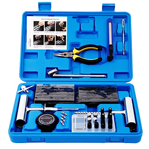
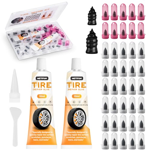
- 【Perfect Emergency Repair Solution】This kit includes...
- 【Premium Materials for Safe Repairs】Our tire screw plugs...
- 【2 Sizes for Every Puncture】Choose the right size for...
- 【5-Minute DIY Repair】Skip the auto shop and fix flats...
- 【Emergency-Ready Design】Compact & ready for...
If the PDF is very large, it may not load in the preview below.
Some older TSBs had multiple PDFs — visit the NHTSA Website to view all PDFs.
If the TSB PDF does not show, download or view it on the NHTSA Website.
Click on the (+) Plus Sign
Then Click on Associated Document(s)
Search NHTSA Database for Recalls
Search NHTSA Database for Vehicle Investigations
View Latest Vehicle Investigations
Search NHTSA Database for Vehicle Complaints
View Latest Vehicle Complaints
TSB/Document ID: TB441203
Replacement Service Bulletin Number:
MFR Communication Date: 2012-11-02
MFR Internal Campaign ID/Software Version:
Communication Type: Service Bulletin/Repair Instructions
NHTSA Components: WHEELS
MFR Component System:
MFR Component Subsystem:
Previous TSB | Next TSB |

- [Notice] When you receive a used device, it may be a customer return resold by Amazon without inspection. You can exchange it for a new one through Amazon. As this situation is unavoidable, we sincerely apologize. For any issues, contacting us via Amazon's "Messages" is the best way. THINKSCAN 689BT Bidirectional Scan Tool Can Be Used Immediately After It is Turned On, Without Complicated Registration Process, Which is More Convenient & Quick.
- Full Bi-Directional Control & 3000+ Active Tests: Take control and test components like actuators, fuel injectors, relays, and cooling fans in real time. You’ll quickly see if the problem is in the part itself or the control module — saving you hours of guesswork and frustrating trial-and-error.
- Advanced ECU Coding Capabilities: Handle module matching and hidden feature activation with confidence. When you replace an ECU or want to customize settings, this obd2 scanner diagnostic bi directional tool gives you the professional-level capabilities you need without the dealership price tag.
- 34+ Useful Reset and Maintenance Functions: Complete everyday service tasks smoothly with a wide range of helpful reset and maintenance functions. Whether you’re keeping up with regular upkeep or tackling a specific job, this scanner makes maintenance simpler and less stressful for both DIYers and pros.
- Comprehensive Full System Diagnostics: Diagnose every major system — Engine, Transmission, ABS, SRS, TPMS, and more — all in one place. Finally stop wondering if you’re missing something important; get the full picture and clear codes with ease.

- Top Reasons to Choose the D7S OBD2 Scanner: XTOOL D7S car scan tool, an upgrade of XTOOL D7, offers comprehensive features for automotive technicians, workshops, and DIY enthusiasts 1. Upgraded Hardware: 2+64GB memory, rear camera, intuitive interface, foldable bracket 2. Complete Diagnostics: FCA
 Autoauth, OE-level all system scan, 39+ maintenance services, 4K+ bidirectional, CANFD/DoIP protocol 3. Advanced Capabilities: ECU c0ding, PMI functions 4. Wide Compatibility: Support 10,000+ models, covering 99% vehicle brands 5. Multi-language: Available in 22+ languages, No IP Restrictions 6. 3-Year Updates: Save 300 bucks on software updates for the latest features and optimizations
 - 2026 Upgraded D7S Car Scanner Features: The newly 2026 D7S V2.0 scanner for car brings exciting features for advanced vehicle diagnostics and enhanced user experience 1. FCA AutoAuth: Now supports FCA SGW module for Chrysler, for Jeep, for Dodge (2018+), for Fiat (2017+), enabling faster vehicle communication without gateway restrictions 2. PMI (Offline ECU Pr0gramming): Allows for Ford, for Lincoln, and for Mazda ECU pr0gramming for new modules 3. Optimized Diagnostic Report 2.0: Personalized reports with logos and customer info for auto shops. Note: Compatibility varies by cars, please check before order
- 39+ Services/Resets/Adaptations/Relearns/Calibrations: XTOOL D7S full system car scanner diagnostic tool tackles 99% of common car issues through its 36+ special functions, including Oil Reset, EPB, SAS, BMS, Throttle Reset, Injector C0ding, ABS Bleed, TPMS Reset, Power Balance, etc and also covers specific-vehicle functions like Crank Sensor Relearn, ABS Initialization, Cylinder Power Balance, Fuel Trim Reset, Idle Relearn etc. This car diagnostic scanner enhances efficiency, making repairs and maintenance hassle-free. Tip: DO NOT for All vehicles, please check compatibility first
- Cost-effective ECU C0ding Scan Tool for Specific Brands: Enhance your vehicle's performance with XTOOL D7S! This obd2 scanner all systems bidirectional offers advanced capabilities at an affordable price, supports online for BMW, for Benz and offline for BENZ, for MIT, along with PMI functions for Ford, for Mazda, and for Lincoln. Ideal for technicians and DIY enthusiasts, this automotive scanner diagnostic tool optimizes vehicle performance and enhances the driving experience. Note: Not for all cars and modules, please send car VIN to check the compatibility before purchase
- OE All System Diagnostic & 8 Pids Graphing: XTOOL D7S is a comprehensive all system bi directional obd2 scanner that delivers dealer-level diagnostics, completely controlling over your vehicle’s performance and health. This automotive scan tool can read and clear DTCs, view live data and ECU information, retrieve freeze frames, and perform active tests and full obd2 functions. This bi-directional scan tool can can identify your vehicle's make, model, and year information with just one click and show up to 8 PIDs live data with options for CSV viewing, playback, and recording for in-depth analysis. It is easy-to-use for both professionals and beginners, helping pinpoint issues efficiently

- 【✅Compared to BOSSCOMM IF742, IF745 Offers Full-System Diagnostics】The BOSSCOMM IF745 car diagnostic scanner is an upgraded model of IF742. In addition to supporting all OBD2 Code Reader functions and 6 reset options (ABS/EPB/SAS/BMS/Oil/Throttle), it expands diagnostics from 4 systems (Check Engine/ABS/SRS/Transmission) to vehicle All systems, including Steering, Suspension, and Body Electronics. This provides deeper, more comprehensive diagnostic capabilities.
- 【✨10 OBD2 Functions】The BOSSCOMM IF745 scan tool’s DTC Lookup instantly translates fault codes into user-friendly explanations, its I/M Readiness feature streamlines emissions testing with a single tap, and Freeze Frame lets you pinpoint the exact moment of a fault for in-depth root-cause diagnosis. Combined with a live data dashboard and advanced diagnostics (O2S, OBMon, EVAP), it delivers comprehensive insights for confident troubleshooting.
- 【✨Deep Diagnostics for All Vehicle System Modules】Beyond code reading/clearing and ECU information retrieval, our all-in-one data stream feature lets you inspect all current fault codes and their locations across the vehicle’s systems. This vehicle code reader helps you turn off dashboard warning lights and perform a comprehensive self-check of your car at home—no more back-and-forth trips to the repair shop or hefty inspection fees.
- 【✨6 Essential Resets: ABS Bleeding, Oil, EPB, SAS, Throttle, BMS】The BOSSCOMM IF745 obd2 scanner diagnostic tool swiftly purges air from brake lines to restore braking sensitivity, fine-tunes maintenance cycles to eliminate false alerts, resolves parking brake issues with one-click control, recalibrates steering sensors for stability, optimizes engine idling/acceleration for smoother performance, and deeply resets battery systems to extend lifespan and range via precise parameter adjustments.❗NOTE: Does NOT support bidirectional control, coding, or programming.
- 【✨10,000+ Car Models, AutoVIN, 13 Languages】The BOSSCOMM IF745 vehicle scanner diagnostic tool covers 73+ global car brands and offers support in 13 languages, making it perfect for DIYers, auto mechanics, or as a thoughtful gift. With a single-click AutoVIN feature, it instantly retrieves vehicle serial numbers, streamlining diagnostics for users globally. This adaptable tool balances user-friendliness with precision, catering to both personal and professional requirements.✅Unsure about compatibility? Compatibility will vary on vehicles' model and year, pls reach us via 📧 [email protected] 📧 before purchase.

This product presentation was made with AAWP plugin.