
NHTSA ID Number: 10225245
Manufacturer Communication Number: Z27
TSB/Document Date: 2022-10-31
Summary
Customer Satisfaction Notification Z27 PHEV Battery Replacement
vehicle must verify that the system remains powered down during high
voltage repairs.
• This is done by removing the test points access cover.
• The high voltage power down procedure must be performed to
ensure that the high voltage battery is properly powered down.
• The technician must know the whereabouts of the test points access
cover throughout the repair.
• The technician must ensure that the test points access cover is not
reinstalled while service is being performed.
• The technician must recheck that the test points access cover has not
been reinstalled in cases where the vehicle was unattended.
Customer Satisfaction Notification Z27 – PHEV
Battery Replacement
Page 16
Service Procedure [Continued]
3. Prepare the work area and familiarize yourself with all HIGH-VOLTAGE
SAFETY PROCEDURES related to personal safety and vehicle safety
associated with working on a Plug-In Hybrid Electric Vehicle (PHEV). See
High Voltage Safety Procedures in Service Library section 08, Standard
Procedures.
4. Inspect all orange high-voltage cables, and high-voltage components labeled
with the high-voltage symbol for physical damage. If damage is present, extra
caution must be taken to avoid contact with unprotected high-voltage. Do not
insert probes, tools, objects or fluids into damaged high-voltage cables or
components.
5. Disconnect any charging equipment. Do not plug in the EVSE Recharge
Coupler when working on the vehicle.
6. Turn the ignition to Off by pressing
the keyless go button (1) and move
keys away from the car a minimum
of 20 feet (Figure 1).
Figure 1 – Keyless Go Button
NOTE: If the READY indicator is NOT illuminated in instrument cluster,
the vehicle is already shut off. DO NOT push the start/stop button as the
vehicle may start.
7. Wait five minutes to allow the high-voltage system to shut down without
setting a fault code.
8. Disconnect the IBS wire harness connector. Remove and isolate the negative
battery cable using Covers, HEV Battery Terminal 2035100082.
Customer Satisfaction Notification Z27 – PHEV
Battery Replacement
Page 17
Service Procedure [Continued]
9. Remove the F09 (5 amp) fuse from the Power Distribution Center (PDC).
NOTE: This removes the fused B+ power supply to the IDCM. Disabling
the IDCM disables the DC/DC conversion between the HV battery and the
charging output to the low voltage side of the system.
10. Verify the multi-meter is operating correctly by measuring voltage from a
known good power source, such as the vehicle’s 12-volt battery. If at any point
during the procedure, the multi-meter settings are changed, or the probes are
repositioned in the meter, verification with a known good power source must be
repeated.
11. Using a multi-meter, check for voltage at the PDC fused B+ terminal to verify
the low voltage system is powered down. The 12 volt electrical system is now
powered down. There should be no voltage present with the IDCM disabled and
the 12 volt battery disconnected.
12. The high voltage service test points
access cover is located on the battery
pack, under driver side rear seat
cushion (Figure 2).
13. Remove the M6 Torx screws from
the high voltage service test points
access cover (Figure 2).
14. Carefully remove the test points
access cover and set in a protected
location such that the cover plate
alignment and HVIL pins are not
damaged (Figure 2).
Figure 2 – High Voltage Test Point
Access Cover
NOTE: Lift the cover straight up to avoid bending or damaging the pin on
the cover that is used to engage the HVIL switch.
Customer Satisfaction Notification Z27 – PHEV
Battery Replacement
Page 18
Service Procedure [Continued]
15. Removal of the test points access cover will affect the following:
• Disables the High Voltage Battery System by disengaging the internal High
Voltage Interlock (HVIL) pin from the switch.
• Provides access to the high voltage positive and high voltage negative test
points.
NOTE: These circuits are a sense circuit connected through large resistors
inside the high voltage battery to the high voltage bus cables after the
contactors. These circuits are safe even when high voltage is present on the
circuits due to the large resistors reducing these circuits to milliamperes.
• Provides access to the fuse cover screw.
• Allows access to a service lockout loop.
16. Install a lockout-tagout padlock to
the service lockout loop (5) to
prevent test points access cover
installation and re-engaging HVIL
pin (Figure 3).
Figure 3 – Service Lockout Loop
1 - Fuse Cover Screw
2 - Switch
3 - High Voltage (+) Test Port
4 - High Voltage (-) Test Port
5 - Service Lockout Loop
Customer Satisfaction Notification Z27 – PHEV
Battery Replacement
Page 19
Service Procedure [Continued]
17. Use of an insulation tester such as
the Fluke Meter, Multi 126-1587 is
recommended for PHEV circuit
testing. Perform the multi-meter
functionality tests per the
manufactures directions. Verify the
multi-meter is operating correctly by
measuring voltage from a known
good power source, such as the
vehicle’s 12-volt battery. If at any
point during the procedure, the
multi-meter settings are changed, or
the probes are repositioned in the
meter, verification with a known
good power source must be repeated
(Figure 4).
Figure 4 – Fluke Meter, Multi 126-1587
NOTE: Always observe these precautions prior to taking a high-voltage
measurement:
• Be sure to utilize the proper Personal Protection Equipment (PPE)
when working on any high voltage system.
• Rated and non-expired rubber insulating gloves with leather
protectors.
• Have known good test leads.
• Verify the multi-meter leads are rated “CAT III 1,000V”. This
should be printed on the multi-meter leads.
• Install the multi-meter leads in the BLACK and RED sockets on the
right side of the Fluke 1587 (VΩ (RED) and COM (BLACK)).
• Switch the FLUKE 1587 to the DC Volts selection and press the
RANGE button until the 500V range is selected - just one digit (a
zero) is displayed.
• Test the multi-meter operation by measuring the voltage across the
12 volt Battery.
Customer Satisfaction Notification Z27 – PHEV
Battery Replacement
Page 20
Service Procedure [Continued]
18. Using the Fluke multi-meter, measure
the voltage at the high voltage positive
and high voltage negative test points
(Figure 5):
• Measure for voltage between the
positive and negative high voltage
test points.
• Measure for voltage between positive
test point and chassis ground.
• Measure for voltage between
negative test point and chassis
ground.
Figure 5 – Measuring at High Voltage
Test Points
19. The voltage reading should be 0 volts. (Some residual voltage may be present,
up to 2.0 volts may be normal) (Figure 5).
• If the voltage measured is below 2 volts, it is safe to work on the high-voltage
components with the exception of the high-voltage battery internal
components.
• If the voltage is greater than 60 volts, an internal condition exists within the
high voltage battery such as stuck contactors, that are preventing it from being
powered down. This should be accompanied by contactor stuck DTCs. Do not
attempt to carry out testing on any of the vehicle’s high-voltage components
or wiring. The HV Battery Pack requires replacement. Reference the HV
BATTERY SERVICING WITH WELDED CONTACTOR(S) procedure at
the top of the HV PHEV BATTERY REMOVAL AND INSTALLATION
procedure for safely removing a high voltage battery that will not power down
(Refer to 08 - Electrical/Battery System/BATTERY/Removal and
Installation).
Customer Satisfaction Notification Z27 – PHEV
Battery Replacement
Page 21
Service Procedure [Continued]
• If the voltage is between 2.0 volts and 60 volts, the HV system is safe to work
on, however there is a problem that should be diagnosed. Disconnect each of
the following HV modules one at a time and check the voltage at the test
points. If the voltage drops to 2.0 volts or less, the faulted module has been
found. Reconnect each module before continuing to the next.
o Integrated Dual Charger Module (IDCM)
o Electronic A/C Compressor (EAC)
o Battery Coolant Heater
o HV Coolant Heater
o Power Inverter Module (PIM)
20. After confirming that the high voltage battery is powered down and locked out
it is safe to power up the 12-volt system if needed to perform diagnostics or
repairs.
B. HV Battery Removal
21. Loosen the cap on the high voltage cooling reservoir.
22. Raise and support the vehicle.
23. Position a drain pan under the
coolant hoses (Figure 6).
24. Remove the coolant hoses from the
coolant line and drain the power
electronics cooling system
(Figure 6).
25. Once the system is completely
drained, reinstall the coolant hose to
the coolant line (Figure 6).
Figure 6 – Coolant Hoses
Customer Satisfaction Notification Z27 – PHEV
Battery Replacement
Page 22
Service Procedure [Continued]
26. Remove the fasteners (1) and the
skid plate (2) from the vehicle
(Figure 7).
Figure 7 – Skid Plate
27. Disconnect the HV wire harness
connectors (1) and (2) from the HV
battery (Figure 8).
28. Cap the HV cables using Covers,
HEV Battery Terminal 2035100082.
NOTE: A Plug-in Hybrid Electric
Vehicle (PHEV) HV Battery
Cover/Plug Kit is also available
from Mopar® Parts.
29. Remove the support and lower the
vehicle.
Figure 8 – HV Battery Wiring
Connectors
30. Using a trim stick, release and
remove the B-pillar trim cover (1)
(Figure 9).
Figure 9 – B-pillar Trim Cover
Customer Satisfaction Notification Z27 – PHEV
Battery Replacement
Page 23
Service Procedure [Continued]
31. Disconnect the wire harness
connector (2) and release the door
tether from the support bracket (1)
(Figure 10).
Figure 10 – Harness to Support
Bracket
32. Remove the bolt (2) securing the
door check (1) (Figure 11).
Figure 11 – Door Check Bolt
Customer Satisfaction Notification Z27 – PHEV
Battery Replacement
Page 24
Service Procedure [Continued]
33. Remove the nuts (3) and lift the door
up off hinges (1) and remove
(Figure 12).
34. Raise the rear seat cushion.
Figure 12 – Hinge Pin Nuts
35. Remove the fasteners (1) from the
side high voltage battery trim panels
(2) (Figure 13).
36. Using a trim stick or equivalent,
remove the high voltage trim panel
upward to release the retainers and
remove the trim panel. Repeat for
the passenger side.
37. Lower the rear seat cushion.
Figure 13 – HV Battery Side Trim
Customer Satisfaction Notification Z27 – PHEV
Battery Replacement
Page 25
Service Procedure [Continued]
38. Using a trim stick or equivalent,
release the retainers from the front
high voltage battery closeout and
remove from vehicle (Figure 14).
Figure 14 – HV Battery Front Trim
39. Remove the rear seat to load floor gap
hider (Figure 15).
Figure 15 – Gap Hider
Customer Satisfaction Notification Z27 – PHEV
Battery Replacement
Page 26
Service Procedure [Continued]
40. Disconnect the wire harness
connectors, if equipped (4)
(Figure 16).
41. Remove the nut for the center seat
belt anchor (6). Remove the seat
belts from the floor stud (Figure 16).
42. Remove the rear seat fasteners (2) at
the rear of the seat (Figure 16).
Figure 16 – Rear Seat Components
1 - Rear Seat
2 - Rear Seat Nuts
5 - Seat Belts
6 - Center Seat Belt
Anchor nut
43. Disconnect the wire harness
connectors (3), if equipped
(Figure 17).
44. Remove the bolts (1) at the front of
the rear seat. Discard the old bolts.
(Figure 17).
Figure 17 – Rear Seat Components
1 - Rear Seat Bolts
2 - Wire Harness Connectors
3 - Rear Seat
Customer Satisfaction Notification Z27 – PHEV
Battery Replacement
Page 27
Service Procedure [Continued]
45. Remove silencer pad (Figure 18).
46. Remove the seat from the vehicle.
SILENCER PAD
Figure 18 – Silencer Pad
47. Remove the fastener (1) and the
chassis ground cable from the HV
battery (2) (Figure 19).
Figure 19 – HV Battery Fastener and
Ground Cable
Customer Satisfaction Notification Z27 – PHEV
Battery Replacement
Page 28
Service Procedure [Continued]
48. Disconnect the HV wire harness
connectors (1) (Figure 20).
Figure 20 – HV Wire Harness
Connectors
NOTE: Use an absorbent pad to collect any coolant that may leak from the
battery into the interior of the vehicle.
49. Disconnect and plug the HV battery
coolant line connectors (1)
(Figure 21).
Figure 21 – HV Battery Coolant
Connectors
Customer Satisfaction Notification Z27 – PHEV
Battery Replacement
Page 29
Service Procedure [Continued]
NOTE: The HV battery pack weighs 167 kg (368 lb.).
50. Remove the bolts (1) securing
the HV battery to the vehicle
(Figure 22).
Figure 22 – HV Battery Bolts
51. Install two Eyebolt, 10mm
2035203080 with the nuts to the
front support mounting holes (1)
(Figure 23).
Figure 23 – Support Mounting Holes
52. Thread the other two Eyebolt,
10mm 2035203080 (1) into the
threaded holes next to the HV
battery pack mounting bolt holes
(2) on the rear side of the HV
battery pack (Figure 24).
Figure 24 – Eyebolt Installation
Customer Satisfaction Notification Z27 – PHEV
Battery Replacement
Page 30
Service Procedure [Continued]
53. Connect the Lift Straps, HV
Battery 2035200080 to the
eyebolts and the lifting device.
Adjust the straps so that the
battery will be level during
lifting as shown in the picture
(Figure 25).
54. Remove the HV battery pack
from the vehicle.
NOTE: When the HV battery pack is being replaced:
• Refer to the information supplied with the NEW battery. I-sheets for
the HV batteries, how to open the containers and handle the
batteries, can be found on DealerCONNECT on the PARTS tab
under RETURNS.
• All coolant must be removed from the battery. Use a shop air supply
hose connected to the battery coolant inlet port. Adjust the air
pressure regulator to not exceed 100 kPa (15 psi) and force the
coolant from the battery coolant outlet port.
• All coolant ports and electrical connections must be capped.
• Place the HV battery pack in the shipping container or on the
containers lid attached foam pads to prevent damage to the
underside of the battery.
• The battery terminals shall be covered with protection caps while
handling to avoid short circuits and other electrical hazards and to
protect the terminals from dust, dirt and moisture.
• Operate this Li-Ion cell based high voltage battery system only if you
are fully acquainted with all the controls/connections and the safety
procedures/instructions.
Customer Satisfaction Notification Z27 – PHEV
Battery Replacement
Page 31
Service Procedure [Continued]
• Keep the battery system always in position equivalent to the
mounting position in the car (note: slight tilting of the HVBS while
moving by a fork-lift trolley is OK).
• Never place the HVBS on any surface, such as a table or the ground,
other than the supplied crate/dunnage, or the designed vehicle
position.
• Do not store the battery system together with metal or other heavy
objects which can fall onto or hit the HVBS possibly leading to
electrolyte leakage, overheating, smoke, burst and/or ignition.
• SDI storage requirements:
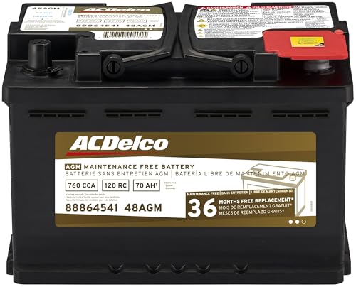
- High density negative paste, improves performance and...
- Enhanced life alloy or Silver Calcium stamped alloy...
- Calcium lead positive grid, maximizes conductivity and...
- Robust envelope separator with puncture resistant back...
- Vent cap design that resists acid leakage

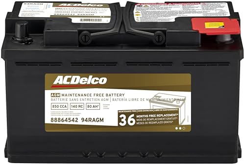
- High density negative paste, improves performance and...
- Enhanced life alloy or Silver Calcium stamped alloy...
- Calcium Lead positive grid, maximizes conductivity and...
- Robust Envelope Separator with puncture-resistant back...
- Vent cap design that resists acid leakage
If the PDF is very large, it may not load in the preview below.
Some older TSBs had multiple PDFs — visit the NHTSA Website to view all PDFs.
If the TSB PDF does not show, download or view it on the NHTSA Website.
Click on the (+) Plus Sign
Then Click on Associated Document(s)
Search NHTSA Database for Recalls
Search NHTSA Database for Vehicle Investigations
View Latest Vehicle Investigations
Search NHTSA Database for Vehicle Complaints
View Latest Vehicle Complaints
TSB/Document ID: Z27
Replacement Service Bulletin Number:
MFR Communication Date: 2022-08-25
MFR Internal Campaign ID/Software Version:
Communication Type: Service Bulletin/Repair Instructions
NHTSA Components: ELECTRICAL SYSTEM:12V/24V/48V BATTERY
MFR Component System:
MFR Component Subsystem:
Previous TSB | Next TSB |

- [Notice] When you receive a used device, it may be a customer return resold by Amazon without inspection. You can exchange it for a new one through Amazon. As this situation is unavoidable, we sincerely apologize. For any issues, contacting us via Amazon's "Messages" is the best way. THINKSCAN 689BT Bidirectional Scan Tool Can Be Used Immediately After It is Turned On, Without Complicated Registration Process, Which is More Convenient & Quick.
- Full Bi-Directional Control & 3000+ Active Tests: Take control and test components like actuators, fuel injectors, relays, and cooling fans in real time. You’ll quickly see if the problem is in the part itself or the control module — saving you hours of guesswork and frustrating trial-and-error.
- Advanced ECU Coding Capabilities: Handle module matching and hidden feature activation with confidence. When you replace an ECU or want to customize settings, this obd2 scanner diagnostic bi directional tool gives you the professional-level capabilities you need without the dealership price tag.
- 34+ Useful Reset and Maintenance Functions: Complete everyday service tasks smoothly with a wide range of helpful reset and maintenance functions. Whether you’re keeping up with regular upkeep or tackling a specific job, this scanner makes maintenance simpler and less stressful for both DIYers and pros.
- Comprehensive Full System Diagnostics: Diagnose every major system — Engine, Transmission, ABS, SRS, TPMS, and more — all in one place. Finally stop wondering if you’re missing something important; get the full picture and clear codes with ease.

- Top Reasons to Choose the D7S OBD2 Scanner: XTOOL D7S car scan tool, an upgrade of XTOOL D7, offers comprehensive features for automotive technicians, workshops, and DIY enthusiasts 1. Upgraded Hardware: 2+64GB memory, rear camera, intuitive interface, foldable bracket 2. Complete Diagnostics: FCA
 Autoauth, OE-level all system scan, 39+ maintenance services, 4K+ bidirectional, CANFD/DoIP protocol 3. Advanced Capabilities: ECU c0ding, PMI functions 4. Wide Compatibility: Support 10,000+ models, covering 99% vehicle brands 5. Multi-language: Available in 22+ languages, No IP Restrictions 6. 3-Year Updates: Save 300 bucks on software updates for the latest features and optimizations
 - 2026 Upgraded D7S Car Scanner Features: The newly 2026 D7S V2.0 scanner for car brings exciting features for advanced vehicle diagnostics and enhanced user experience 1. FCA AutoAuth: Now supports FCA SGW module for Chrysler, for Jeep, for Dodge (2018+), for Fiat (2017+), enabling faster vehicle communication without gateway restrictions 2. PMI (Offline ECU Pr0gramming): Allows for Ford, for Lincoln, and for Mazda ECU pr0gramming for new modules 3. Optimized Diagnostic Report 2.0: Personalized reports with logos and customer info for auto shops. Note: Compatibility varies by cars, please check before order
- 39+ Services/Resets/Adaptations/Relearns/Calibrations: XTOOL D7S full system car scanner diagnostic tool tackles 99% of common car issues through its 36+ special functions, including Oil Reset, EPB, SAS, BMS, Throttle Reset, Injector C0ding, ABS Bleed, TPMS Reset, Power Balance, etc and also covers specific-vehicle functions like Crank Sensor Relearn, ABS Initialization, Cylinder Power Balance, Fuel Trim Reset, Idle Relearn etc. This car diagnostic scanner enhances efficiency, making repairs and maintenance hassle-free. Tip: DO NOT for All vehicles, please check compatibility first
- Cost-effective ECU C0ding Scan Tool for Specific Brands: Enhance your vehicle's performance with XTOOL D7S! This obd2 scanner all systems bidirectional offers advanced capabilities at an affordable price, supports online for BMW, for Benz and offline for BENZ, for MIT, along with PMI functions for Ford, for Mazda, and for Lincoln. Ideal for technicians and DIY enthusiasts, this automotive scanner diagnostic tool optimizes vehicle performance and enhances the driving experience. Note: Not for all cars and modules, please send car VIN to check the compatibility before purchase
- OE All System Diagnostic & 8 Pids Graphing: XTOOL D7S is a comprehensive all system bi directional obd2 scanner that delivers dealer-level diagnostics, completely controlling over your vehicle’s performance and health. This automotive scan tool can read and clear DTCs, view live data and ECU information, retrieve freeze frames, and perform active tests and full obd2 functions. This bi-directional scan tool can can identify your vehicle's make, model, and year information with just one click and show up to 8 PIDs live data with options for CSV viewing, playback, and recording for in-depth analysis. It is easy-to-use for both professionals and beginners, helping pinpoint issues efficiently

- 【✅Compared to BOSSCOMM IF742, IF745 Offers Full-System Diagnostics】The BOSSCOMM IF745 car diagnostic scanner is an upgraded model of IF742. In addition to supporting all OBD2 Code Reader functions and 6 reset options (ABS/EPB/SAS/BMS/Oil/Throttle), it expands diagnostics from 4 systems (Check Engine/ABS/SRS/Transmission) to vehicle All systems, including Steering, Suspension, and Body Electronics. This provides deeper, more comprehensive diagnostic capabilities.
- 【✨10 OBD2 Functions】The BOSSCOMM IF745 scan tool’s DTC Lookup instantly translates fault codes into user-friendly explanations, its I/M Readiness feature streamlines emissions testing with a single tap, and Freeze Frame lets you pinpoint the exact moment of a fault for in-depth root-cause diagnosis. Combined with a live data dashboard and advanced diagnostics (O2S, OBMon, EVAP), it delivers comprehensive insights for confident troubleshooting.
- 【✨Deep Diagnostics for All Vehicle System Modules】Beyond code reading/clearing and ECU information retrieval, our all-in-one data stream feature lets you inspect all current fault codes and their locations across the vehicle’s systems. This vehicle code reader helps you turn off dashboard warning lights and perform a comprehensive self-check of your car at home—no more back-and-forth trips to the repair shop or hefty inspection fees.
- 【✨6 Essential Resets: ABS Bleeding, Oil, EPB, SAS, Throttle, BMS】The BOSSCOMM IF745 obd2 scanner diagnostic tool swiftly purges air from brake lines to restore braking sensitivity, fine-tunes maintenance cycles to eliminate false alerts, resolves parking brake issues with one-click control, recalibrates steering sensors for stability, optimizes engine idling/acceleration for smoother performance, and deeply resets battery systems to extend lifespan and range via precise parameter adjustments.❗NOTE: Does NOT support bidirectional control, coding, or programming.
- 【✨10,000+ Car Models, AutoVIN, 13 Languages】The BOSSCOMM IF745 vehicle scanner diagnostic tool covers 73+ global car brands and offers support in 13 languages, making it perfect for DIYers, auto mechanics, or as a thoughtful gift. With a single-click AutoVIN feature, it instantly retrieves vehicle serial numbers, streamlining diagnostics for users globally. This adaptable tool balances user-friendliness with precision, catering to both personal and professional requirements.✅Unsure about compatibility? Compatibility will vary on vehicles' model and year, pls reach us via 📧 [email protected] 📧 before purchase.
This product presentation was made with AAWP plugin.