
NHTSA ID Number: 10223604
Manufacturer Communication Number: 2100815
TSB/Document Date: 2022-10-17
Summary
Transmission Shift Quality C-Clutch Snap Ring This bulletin involves removing the transmission, disassembling, and replacing the C-Clutch snap ring. A small number of customers may experience less than desired shift quality during a 5-4 downshift and/or Malfunction Indicator Lamp (MIL) Illumination. Upon further inspection, the technician may find Diagnostic Trouble Code (DTC) U0402 setting in the Powertrain Control Module (PCM) memory.
NUMBER:
21-008-15
GROUP:
Transmission and
Transfer Case
DATE:
February 05, 2015
This bulletin is supplied as technical information only and is not an authorization for repair. No part of this publication may be reproduced, stored in a retrieval system,
or transmitted, in any form or by any means, electronic, mechanical, photocopying, or otherwise, without written permission of Chrysler Group LLC.
THIS SERVICE BULLETIN IS ALSO BEING RELEASED AS RAPID RESPONSE
TRANSMITTAL (RRT) 15-006. ALL APPLICABLE SOLD AND UN-SOLD RRT VIN's
HAVE BEEN LOADED. TO VERIFY THAT THIS RRT SERVICE ACTION IS
APPLICABLE TO THE VEHICLE, USE VIP OR PERFORM A VIN SEARCH IN
TECHCONNECT. ALL REPAIRS ARE REIMBURSABLE WITHIN THE PROVISIONS OF
WARRANTY.
SUBJECT:
Transmission Shift Quality C-Clutch Snap Ring
OVERVIEW:
This bulletin involves removing the transmission, disassembling, and replacing the
C-Clutch snap ring.
MODELS:
2014-2015
(KL)
Jeep Cherokee
2015
(UF)
Chrysler 200
NOTE: This bulletin applies to the following vehicles equipped with the 948TE 9
speed transmission (sales code DFH or DFJ).
• KL vehicles built on or after June 26, 2013 (MDH 0626XX) and on or
before December 1, 2014 (MDH 1201XX) equipped with a 2.4L engine
(sales code ED6 or ED8) or 3.2L engine (sales code EHB).
• UF vehicles built on or after May 9, 2014 (MDH 0509XX) and on or
before October 23, 2014 (MDH 1023XX) equipped with a 2.4L engine
(sales code ED6 or ED8).
SYMPTOM/CONDITION:
A small number of customers may experience less than desired shift quality during a 5-4
downshift and/or Malfunction Indicator Lamp (MIL) Illumination. Upon further inspection,
the technician may find Diagnostic Trouble Code (DTC) U0402 setting in the Powertrain
Control Module (PCM) memory.
DIAGNOSIS:
Using a Scan Tool (wiTECH) with the appropriate Diagnostic Procedures available in
TechCONNECT, verify no other DTCs are set. If DTCs other than the one listed above are
present, record them on the repair order and repair as necessary before proceeding further
with this bulletin.
21-008-15
-2-
Only perform this repair procedure if the customer’s VIN is listed in VIP or your RRT VIN
list.
PARTS REQUIRED:
Qty.
Part No.
Description
1 (AR)
04736949AB
Snap Ring, Transmission C-Clutch
2 (AR)
04736843AA
Oil Seal, Transmission Differential (2WD and
4WD)
(Note: Only one is used on 4wd applications)
1 (AR)
04753061AA
Oil Seal, Transmission Differential (Additional
for 4WD)
2 (AR)
04753043AA
O-Ring, Valve Body Fluid Adapter Tube
10 (AR)
04753042AA
O-Ring, Valve Body Fluid Adapter Tube
(AR)
68218925AA
Transmission Fluid (Qt.)
SPECIAL TOOLS/EQUIPMENT REQUIRED:
8901A
Pressing Tool
10428
Adapter, Pressing Tool
10379
Valve Body Alignment Pins
10504
Compressor, Spring
C-4171
Universal Driver Handle
6888
Installer, Seal
N/A
REPAIR PROCEDURE:
NOTE: Due to the unique nature of this repair, a TechTube training video is available
to help guide technicians through the repair process. Please refer to course
TT02002 anytime during this repair for additional assistance.
1. Remove the transmission. Refer to detailed removal instructions in
DealerCONNECT/TechCONNECT Service Information Section 21 - Transmission and
Transfer Case> Automatic - 948TE> Removal> FWD, AWD/4WD.
WARNING:Always wear safety glasses when cleaning, disassembling and
assembling the transmission/transaxle. Contents of the
transmission/transaxle can become projectiles (E.G., springs, snap-rings,
as well as metal and other debris. Failure to wear safety glasses may
result in severe personal injury.
CAUTION: Tag all snap rings, thrust washers, washers, spacers and thrust bearings,
ect. during disassembly for quick identification and assembly. Failure to
follow these instructions may cause damage to the transmission.
-3-
21-008-15
NOTE: Before disassembling the transmission, wash the transmission with a
suitable solvent and/or pressure washer to remove oily grime and loose dirt.
Place the transmission on a clean work surface with ample fluid drainage
capacity or absorbency.
2. With the transmission secured on a suitable work surface, remove the torque
converter and drain.
3. Remove the transmission drain plug, production fill plug and torque converter pressure
port plugs from the bell housing and drain all transmission fluid. See (Fig. 1), (Fig. 2),
and (Fig. 3).
Fig. 1 Transmission Fluid Drain Plug
1 - Fluid Drain Plug
21-008-15
-4-
Fig. 2 Transmission Production Fill Port
1 - Transmission Control Module (TCM)
2 - Production Fill Port
Fig. 3 Torque Converter Pressure Port
1 - Torque Converter Pressure Port
2 - Transmission Oil Cooler Line Connections
4. Remove the transmission electrical connector retaining clip from the valve body oil pan
and push the connector slightly into the pan.
-5-
21-008-15
5. Remove the valve cover oil pan retaining bolts (Qty 7) and remove the pan.
6. Remove the valve body retaining bolts securing the valve body assembly to the
transmission case. Only 9 bolts will need to be removed in order to remove the valve
body. See (Fig. 4).
Fig. 4 Only Remove Bolts Highlighted
CAUTION: Care must be taken when removing the valve body to avoid damage to
the electrical harness to the Transmission Range Sensor (TRS) and
speed sensor.
7. Using a suitable prying tool, pry the valve body away from the fluid transfer/adapter
tubes.
8. Taking care not to damage the wiring harness, set the valve body aside to gain access
to the TRS and speed sensor bolted to the transmission housing.
9. Remove the TRS and speed sensor retaining bolts and remove the sensors.
10. Set the valve body aside in a clean area until reinstallation.
11. From around the perimeter of the transmission, remove the bellhousing to
transmission housing retaining bolts (Qty 17).
NOTE: Bolt #8 will remain in place throughout this entire procedure while bolt #2 will
be removed in a later step.
12. Remove the inner bellhousing bolts (Qty 11). Do Not remove bolt #2 or #8 at this time.
See (Fig. 5).
21-008-15
-6-
Fig. 5 Inner Bellhousing Bolts
1 - Do not remove these bolts at this time
13. Using wooden blocks to stabilize the transmission on the work surface, position the
transmission on the bench with the bellhousing facing upward.
14. Using a suitable pry bar in the proper pry location, pry upwards to dislodge the
bellhousing from the transmission housing.
15. Lift the bellhousing straight upward and separate the assembly from the transmission
housing. The E-Clutch, Output Gear Sub Assembly (OPSA), and fluid filter will still be
attached to the bellhousing.
16. Remove the bellhousing to transmission housing gasket and set aside.
17. Remove the differential gear assembly.
18. Remove the transfer gear assembly
19. Remove the Gear 4 Annulus and Planetary Pinion Carrier assembly. See (Fig. 6).
-7-
21-008-15
Fig. 6 Gear 4 Planetary Pinion Carrier Assembly
20. Remove the Gear 3 Annulus and Carrier Gear assembly. See (Fig. 7).
Fig. 7 Gear 3 Annulus Gear Assembly
NOTE: It may be necessary to use a 1 inch socket between the bearing puller and
transmission case for clearance.
21. With the transmission properly supported in a suitable arbor press, install pressing tool
8901A (with the pressure scale removed) and pressing tool adapter 10428 over the
D-Clutch piston/retainer. See (Fig. 8).
21-008-15
-8-
Fig. 8 Pressing Tool Installed
22.
23.
24.
25.
Compress the D-Clutch piston retainer assembly and remove the snap ring.
Remove the pressing tool and place the transmission back onto the work bench.
Remove the D-Clutch piston retainer, piston, and belleville spring.
Remove the gear train assembly (annulus gear 3, B-clutch discs and hub, and input
shaft assembly) by lifting upwards on the input shaft. See (Fig. 9). Do not lift the
assembly by the hub as this will disengage the hub assembly from the B-Clutch clutch
pack.
Fig. 9 Gear Train Assembly
26.
27.
28.
29.
Remove the D-Clutch clutch pack (plates and fibers).
Remove the C-Clutch clutch pack selectable snap ring.
Remove the C-Clutch clutch pack (plates and fibers).
Install adapter plate 10504 over the C-Clutch belleville spring.
-9-
21-008-15
30. Properly support the transmission assembly into the arbor press and install pressing
tool 8901A (with the pressure scale removed) and pressing tool adapter 10428 on top
of the 10504 adapter plate
31. Compress the belleville spring to allow removal of the C-Clutch snap ring.
32. Remove the C-Clutch snap ring and discard.
33. Remove and discard all differential seals from the transmission housing and
bellhousing.
CAUTION: The work area, counter surfaces, and tools must be thoroughly cleaned
before attempting to assemble the transmission. All of the sub
assemblies should be cleaned and assembled with new sealing
components where applicable.
NOTE: The new C-Clutch snap ring will be installed with the opening in a different
position from the original.
34. Install the new snap ring with the opening rotated 90 degrees counter clockwise from
the original snap ring location. See (Fig. 10) and (Fig. 11).
Fig. 10 Snap Ring Orientation
1 - Original snap ring opening installation location
2 - New snap ring opening installation location
21-008-15
-10-
Fig. 11 New Snap Ring Installed
35. Release pressure on the press and remove the pressing tool and adapter to release
the belleville spring.
36. Verify the new snap ring is properly seated in the groove.
37. Install the C-Clutch clutch pack (plates and fibers) and install the selectable snap ring
into the case.
NOTE: The #8 Needle Thrust Bearing may still be attached to the bottom of the gear
train hub assembly removed in Step #25. Remove the bearing before
installation of the hub assembly.
38. Verify the #8 Needle Thrust Bearing is properly oriented on the Oil Feed Bushing in
the bottom of the case. See (Fig. 12).
Fig. 12 Thrust Bearing Properly Installed
39. Install D-Clutch clutch pack (plates and fibers).
-11-
21-008-15
NOTE: Ensure that the friction plate tabs for the C and D clutch packs are aligned to
help with proper installation of the gear train assembly.
NOTE: A solid audible clunk will be heard if installed correctly.
40. While not allowing the input shaft to slip inward, wriggle the gear train assembly until it
is properly engaged into the C and D-Clutch discs. See (Fig. 13) for proper gear train
assembly installation.
Fig. 13 Gear Train Assembly Properly Seated
1 - D-Clutch hub slightly protruding below D-Clutch clutch pack.
NOTE: Closely inspect the D-Clutch piston and piston retainer o-ring seals for
damage prior to installation.
41. Install the D-Clutch belleville spring, D-Clutch piston, and D-Clutch piston retainer
assembly.
42. With the transmission properly supported in a suitable arbor press, install pressing tool
8901A and pressing tool adapters (10428).
43. Compress the D-Clutch piston retainer until the snap ring grove is exposed.
44. Install the D- Clutch piston retainer snap ring.
45. Remove the pressing tool and remove the transmission from the arbor press.
46. Install the Gear 3 Annulus and Carrier Gear assembly. See (Fig. 14).
21-008-15
-12-
Fig. 14 Gear 3 Annulus Gear Assembly
47. Install the Gear 4 Annulus and Planetary Pinion Carrier assembly. See (Fig. 15).
Fig. 15 Gear 4 Planetary Pinion Carrier Assembly
48. At the bellhousing assembly, remove bolt #2 taking care not to allow the OPSA and
E-clutch assembly drop away from the bellhousing. See (Fig. 16).
-13-
21-008-15
Fig. 16 OPSA Retaining Bolt
1 - OPSA retaining bolt #2
49. Separate the OPSA from the E-Clutch and bell housing and install onto the Planetary
Pinion Carrier assembly making sure the lower gear teeth are properly meshed with
the pinion carrier and transfer tube orifices are properly aligned. See (Fig. 17) and
(Fig. 18).
Fig. 17 OPSA To Carrier Installation
1 - Verify lower OPSA gear teeth are properly meshed.
21-008-15
-14-
Fig. 18 OPSA Fluid Adapter Tube Orifice Orientation
1 - Transmission Fluid Adapter Tube Orifices
50. Remove the E-Clutch clutch pack and hub from the bell housing and while holding the
clutch friction discs and fibers in place inside of the hub, install assembly onto the
OPSA. See (Fig. 19) and (Fig. 20).
Fig. 19 E Clutch And Hub Installation
-15-
21-008-15
Fig. 20 E Clutch And Hub Properly Seated
51. Install the transfer gear assembly.
52. Install the differential gear assembly.
53. Ensure that the transmission fluid port seal is properly installed into the transmission
housing before installing the bellhousing. See (Fig. 21).
Fig. 21 Transmission Fluid Port Seal
54. Install the bellhousing gasket.
55. Carefully lower the bellhousing onto the transmission case. It may be necessary to
rotate the OPSA/E-Clutch assembly slightly to assure proper guide pin alignment into
the bellhousing during installation. See (Fig. 22) for proper final alignement.
21-008-15
-16-
Fig. 22 OPSA To Bellhousing Properly Aligned
1 - Fluid Adapter Tube Orifices Properly Aligned
56. Engage the guide pins in the transmission housing into the receptacle holes in the
bellhousing to assure proper alignment.
57. Install the bellhousing to transmission housing bolts and hand tighten.
58. Install the inner bellhousing bolts and torque, in sequence, to 29 Nm (21 Ft Lbs). See
(Fig. 23).
Fig. 23 Inner Bellhousing Bolt Torque Sequence
59. Torque all remaining bellhousing to transmission case bolts, in sequence, to 29 Nm
(21 Ft Lbs). See (Fig. 24).
-17-
21-008-15
Fig. 24 Transmission Case Bolt Torque Sequence
NOTE: When the internal components are properly installed and transmission case
is torqued, the input shaft end play should be between .07 and .32 in. and
should be able to be rotated with some resistance.
60. Install the 6 valve body fluid adapter tubes, using new o-rings, into the transmission.
Ensure the 2 oblong adapter tubes are properly oriented. See (Fig. 25).
Fig. 25 Transmission Fluid Adapter Tube Orientation
61. Install the 2 larger fluid transfer tubes into the valve body.
62. Place the valve body over the transmission and install the TRS and speed sensor.
Torque retainer bolts to 6.5 Nm (5 Ft Lbs).
CAUTION: Care must be taken when installing the valve body to avoid damaging the
TRS and speed sensor wiring harness.
21-008-15
-18-
63. Align the valve body over the fluid adapter tubes and, while guiding the manual lever
cam into the slot on the manual valve, firmly press the valve body into place.
64. Install the valve body retaining bolts and torque, in sequence, to 11Nm (8 Ft Lbs.). See
(Fig. 26).
Fig. 26 Valve Body Retaining Bolt Torque Sequence
NOTE: A light coating of assembly lube can be applied to the o-ring seals of the
valve body wiring harness electrical connector to ease installation.
65. Place the valve body cover over the valve body and press the harness connector into
the cover until the retainer clip groove is exposed.
66. Install the electrical harness connector retaining clip.
67. Install the valve body fluid cover and torque the retaining bolts to 11Nm (8 Ft Lbs.)
68. Install the transmission. Refer to detailed installation instructions in
DealerCONNECT/TechCONNECT Service Information Section 21 - Transmission and
Transfer Case> Automatic - 948TE> Installation> FWD, AWD/4WD.
69. Fill the transmission to the proper fluid level. Refer to detailed filling instructions in
DealerCONNECT/TechCONNECT Service Information Section 21 - Transmission and
Transfer Case> Automatic - 948TE> Fluid and Filter> Standard Procedure> Fluid
Level Check.
70. Is your vehicle a 2014 KL?
a. Yes>>> Perform the 9 speed Adaptation Drive Learn procedure. Refer to all
applicable published service bulletins regarding the adaptation drive learn for
detailed procedures and labor times. Proceed to Step #79.
b. No>>> Proceed to Step #71.
71. Start the engine and monitor the transmission temperature on the Electronic Vehicle
Information Center (EVIC).
72. With the vehicle located in a suitable area, allow the transmission to warm up to
minimum of 60°C (140°F) by performing the following steps:
a. Apply the service brake.
b. Shift Transmission from Park to Reverse.
c. Shift Transmission from Reverse to Drive.
d. Accelerate the vehicle to minimum of 45 mph to allow the transmission to cycle
through each gear.
-19-
21-008-15
e. Continue to drive the vehicle until the transmission temperature reaches 60°C
(140°F).
NOTE: If the vehicle is equipped with the start/stop feature (sales code XBU) it must
be disabled prior to performing this procedure. To disable, press the on/off
switch located on the center switch bank near the HVAC controls.
73. Connect wiTECH diagnostic scan too to the vehicle.
74. Check for active TCM DTCs (Diagnostic Trouble Codes). Do not perform the Quick
Learn procedure if TCM DTCs are present. Repair transmission as required.
75. Select the TCM module in wiTECH.
76. Select the “Misc Functions” tab.
NOTE: If the “Quick Learn” option does not appear on wiTECH and both the TCM
and PCM were just updated, restart the wiTECH application which should
now be populated with the “Quick Learn” option.
77. Select the “Quick Learn” procedure, and follow the on-screen instructions to reset and
learn the clutch adaptive values.
78. Shift the transmission into Park and shut off the engine. Proceed to Step #79.
79. Procedure complete.
POLICY:
Reimbursable within the provisions of the warranty.
21-008-15
-20-
TIME ALLOWANCE:
Labor
Operation
No:
Description
Skill Category
Amount
21-00-04-95
Snap Ring, Transmission
C-Clutch - Replace
(2.4L KL Only Includes
Transmission Removal And
Installation)
(3 - Highly Skilled)
2 - Automatic Transmission
6.0 Hrs.
21-00-04-96
Snap Ring, Transmission
C-Clutch - Replace
(3.2L KL Only Includes
Transmission Removal And
Installation)
(3 - Highly Skilled)
6.2 Hrs
21-00-04-97
Snap Ring, Transmission
C-Clutch - Replace
(2.4L UF Only Includes
Transmission Removal And
Installation)
(3 - Highly Skilled)
6.5 Hrs
9-Spd 948TE Transmission
Quick Learn Procedure
0.4 Hrs
21-00-04-63
All-Wheel Drive Equipped
(3.2L Equipped)
1.5 Hrs
21-00-04-66
All-Wheel Drive Equipped
(2.4L Equipped)
2 - Automatic Transmission
3.2 Hrs
21-00-04-67
Skid Plate Equipped
0.4 Hrs
Related Op.
21-00-04-50
Opt. Equip.
FAILURE CODE:
ZZ
Service Action

- CUTTING EDGE TECHNOLOGY - Shockproof technology designed to...
- QUIET SMOOTH SHIFTING - V-Twin Transmission oil dampens...
- IMPROVES PERFORMANCE - Transmission fluid that dramatically...
- POPULAR POWESPORTS OIL FOR - UTVs & Side by Sides, ATVs...
- WHY RED LINE - Established in 1979, Red Line Products...
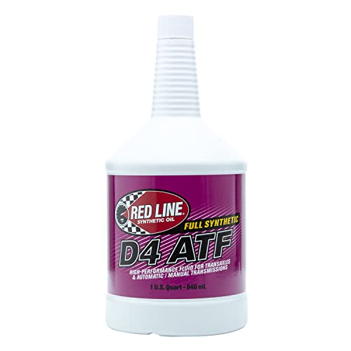
- EXCELLENT - gear and synchro protection, balanced...
- ALSO USED WITH - manual transmissions and transaxles like...
- MOST VERSATILE ATF - use where Dexron III, Dexron II, Mercon...
- POPULAR TRANSMISSION FLUID FOR - Toyota
 Type T-III and T-IV...
 - WHY RED LINE - Established in 1979, Red Line Products...

If the PDF is very large, it may not load in the preview below.
Some older TSBs had multiple PDFs — visit the NHTSA Website to view all PDFs.
If the TSB PDF does not show, download or view it on the NHTSA Website.
Click on the (+) Plus Sign
Then Click on Associated Document(s)
Search NHTSA Database for Recalls
Search NHTSA Database for Vehicle Investigations
View Latest Vehicle Investigations
Search NHTSA Database for Vehicle Complaints
View Latest Vehicle Complaints
TSB/Document ID: 2100815
Replacement Service Bulletin Number:
MFR Communication Date: 2015-02-05
MFR Internal Campaign ID/Software Version:
Communication Type: Service Bulletin/Repair Instructions
NHTSA Components: POWER TRAIN
MFR Component System:
MFR Component Subsystem:
Previous TSB | Next TSB |

- [Notice] When you receive a used device, it may be a customer return resold by Amazon without inspection. You can exchange it for a new one through Amazon. As this situation is unavoidable, we sincerely apologize. For any issues, contacting us via Amazon's "Messages" is the best way. THINKSCAN 689BT Bidirectional Scan Tool Can Be Used Immediately After It is Turned On, Without Complicated Registration Process, Which is More Convenient & Quick.
- Full Bi-Directional Control & 3000+ Active Tests: Take control and test components like actuators, fuel injectors, relays, and cooling fans in real time. You’ll quickly see if the problem is in the part itself or the control module — saving you hours of guesswork and frustrating trial-and-error.
- Advanced ECU Coding Capabilities: Handle module matching and hidden feature activation with confidence. When you replace an ECU or want to customize settings, this obd2 scanner diagnostic bi directional tool gives you the professional-level capabilities you need without the dealership price tag.
- 34+ Useful Reset and Maintenance Functions: Complete everyday service tasks smoothly with a wide range of helpful reset and maintenance functions. Whether you’re keeping up with regular upkeep or tackling a specific job, this scanner makes maintenance simpler and less stressful for both DIYers and pros.
- Comprehensive Full System Diagnostics: Diagnose every major system — Engine, Transmission, ABS, SRS, TPMS, and more — all in one place. Finally stop wondering if you’re missing something important; get the full picture and clear codes with ease.

- Top Reasons to Choose the D7S OBD2 Scanner: XTOOL D7S car scan tool, an upgrade of XTOOL D7, offers comprehensive features for automotive technicians, workshops, and DIY enthusiasts 1. Upgraded Hardware: 2+64GB memory, rear camera, intuitive interface, foldable bracket 2. Complete Diagnostics: FCA Autoauth, OE-level all system scan, 39+ maintenance services, 4K+ bidirectional, CANFD/DoIP protocol 3. Advanced Capabilities: ECU coding, PMI functions 4. Wide Compatibility: Support 10,000+ models, covering 99% vehicle brands 5. Multi-language: Available in 22+ languages, No IP Restrictions 6. 3-Year Updates: Save 300 bucks on software updates for the latest features and optimizations
- 2026 Upgraded D7S Car Scanner Features: The newly 2026 D7S V2.0 scanner for car brings exciting features for advanced vehicle diagnostics and enhanced user experience 1. FCA AutoAuth: Now supports FCA SGW module for Chrysler, for Jeep, for Dodge (2018+), for Fiat (2017+), enabling faster vehicle communication without gateway restrictions 2. PMI (Offline ECU Programming): Allows for Ford, for Lincoln, and for Mazda ECU programming for new modules 3. Optimized Diagnostic Report 2.0: Personalized reports with logos and customer info for auto shops. Note: Compatibility varies by cars, please check before order
- Cost-effective ECU Coding Scan Tool for Specific Brands: Enhance your vehicle's performance with XTOOL D7S! This obd2 scanner all systems bidirectional offers advanced capabilities at an affordable price, supports online for BMW, for Benz and offline for BENZ, for MIT, along with PMI functions for Ford, for Mazda, and for Lincoln. Ideal for technicians and DIY enthusiasts, this automotive scanner diagnostic tool optimizes vehicle performance and enhances the driving experience. Note: Not for all cars and modules, please send car VIN to check the compatibility before purchase
- OE All System Diagnostic & 8 Pids Graphing: XTOOL D7S is a comprehensive all system bi directional obd2 scanner that delivers dealer-level diagnostics, completely controlling over your vehicle’s performance and health. This automotive scan tool can read and clear DTCs, view live data and ECU information, retrieve freeze frames, and perform active tests and full obd2 functions. This bi-directional scan tool can can identify your vehicle's make, model, and year information with just one click and show up to 8 PIDs live data with options for CSV viewing, playback, and recording for in-depth analysis. It is easy-to-use for both professionals and beginners, helping pinpoint issues efficiently
- 3 Years Software Update, Value for Money: With 3 years of software updates and 22+ languages(no IP restrictions), XTOOL D7S auto scanner code scanner ensures ongoing compatibility for the latest car models and improved diagnostic functions. This all system vehicle diagnostic scanner comes with a 30-day return policy and a 24-month repair for dependable performance. XTOOL are dedicated to your satisfaction, so enjoy seamless support and lifetime expert assistance. Should you encounter any issues or concerns, don’t hesitate to reach out XTOOL. D7S with newest update with 22 languages freely transfer without authorization, check details from setting-language or from XTOOL

- 🔥 Historical lowest pr-ice now on sa-le--hot se-lling.
- 【🎈𝗜𝗙𝟳𝟰𝟱 𝗽𝗲𝗿𝗳𝗼𝗿𝗺𝘀 𝟲 𝗲𝘀𝘀𝗲𝗻𝘁𝗶𝗮𝗹 𝗿𝗲𝘀𝗲𝘁 𝗳𝘂𝗻𝗰𝘁𝗶𝗼𝗻𝘀—𝗔𝗕𝗦 𝗕𝗹𝗲𝗲𝗱𝗶𝗻𝗴, 𝗢𝗶𝗹 𝗥𝗲𝘀𝗲𝘁, 𝗘𝗣𝗕, 𝗦𝗔𝗦, 𝗧𝗵𝗿𝗼𝘁𝘁𝗹𝗲 𝗥𝗲𝗹𝗲𝗮𝗿𝗻, 𝗮𝗻𝗱 𝗕𝗠𝗦—𝗽𝘂𝘁𝘁𝗶𝗻𝗴 𝗽𝗿𝗼𝗳𝗲𝘀𝘀𝗶𝗼𝗻𝗮𝗹-𝗴𝗿𝗮𝗱𝗲 𝗺𝗮𝗶𝗻𝘁𝗲𝗻𝗮𝗻𝗰𝗲 𝗯𝗮𝗰𝗸 𝗶𝗻 𝘆𝗼𝘂𝗿 𝗵𝗮𝗻𝗱𝘀.】Spongy brakes? Stuck oil light? Parking brake won't release? Off-center steering? Rough idle after battery disconnect? Draining battery? IF745 handles all with a few taps. One tool covers six dealer-level resets, saving hundreds in labor costs. ❗ NOTE: Does NOT support bidirectional control, coding, or programming.
- 【✨ 𝗜𝗙𝟳𝟰𝟱 𝗴𝗼𝗲𝘀 𝗯𝗲𝘆𝗼𝗻𝗱 𝗯𝗮𝘀𝗶𝗰 𝗰𝗼𝗱𝗲 𝗿𝗲𝗮𝗱𝗶𝗻𝗴 𝘄𝗶𝘁𝗵 𝟭𝟬 𝗶𝗻𝘁𝗲𝗴𝗿𝗮𝘁𝗲𝗱 𝗳𝘂𝗻𝗰𝘁𝗶𝗼𝗻𝘀—𝗗𝗧𝗖 𝗟𝗼𝗼𝗸𝘂𝗽, 𝗜/𝗠 𝗥𝗲𝗮𝗱𝗶𝗻𝗲𝘀𝘀, 𝗙𝗿𝗲𝗲𝘇𝗲 𝗙𝗿𝗮𝗺𝗲, 𝗟𝗶𝘃𝗲 𝗗𝗮𝘁𝗮, 𝗢𝟮𝗦, 𝗢𝗕𝗠, 𝗘𝗩𝗔𝗣, 𝗮𝗻𝗱 𝗺𝗼𝗿𝗲. 】Pulling a code tells you something is wrong. IF745 tells you what the code means, when the fault happened, and what data surrounds it. Pass emissions with one I/M Readiness tap. Freeze the fault moment with Freeze Frame. Monitor live sensor data in real time. Turn cryptic codes into clear answers.
- 【🛒 𝗜𝗙𝟳𝟰𝟱 𝗽𝗲𝗿𝗳𝗼𝗿𝗺𝘀 𝗳𝘂𝗹𝗹-𝘀𝘆𝘀𝘁𝗲𝗺 𝗱𝗶𝗮𝗴𝗻𝗼𝘀𝘁𝗶𝗰𝘀 𝗮𝗰𝗿𝗼𝘀𝘀 𝗮𝗹𝗹 𝗺𝗼𝗱𝘂𝗹𝗲𝘀—𝗲𝗻𝗴𝗶𝗻𝗲, 𝗔𝗕𝗦, 𝗮𝗶𝗿𝗯𝗮𝗴, 𝘁𝗿𝗮𝗻𝘀𝗺𝗶𝘀𝘀𝗶𝗼𝗻, 𝘀𝘁𝗲𝗲𝗿𝗶𝗻𝗴, 𝘀𝘂𝘀𝗽𝗲𝗻𝘀𝗶𝗼𝗻, 𝗯𝗼𝗱𝘆 𝗲𝗹𝗲𝗰𝘁𝗿𝗼𝗻𝗶𝗰𝘀, 𝗮𝗻𝗱 𝗺𝗼𝗿𝗲. 】Warning lights on but you don't know why? Skip the $100+ diagnostic fee at the shop. Run a complete self-check from your driveway. IF745 reads and clears fault codes, retrieves ECU info, and displays live data from every accessible module—delivering a full vehicle health report in minutes, without leaving home.
- 【✅𝗜𝗙𝟳𝟰𝟱 𝗳𝗲𝗮𝘁𝘂𝗿𝗲𝘀 𝗮 𝟳-𝗶𝗻𝗰𝗵 𝗱𝗶𝘀𝗽𝗹𝗮𝘆, 𝗲𝗿𝗴𝗼𝗻𝗼𝗺𝗶𝗰 𝗱𝗲𝘀𝗶𝗴𝗻, 𝗪𝗶-𝗙𝗶 𝘂𝗽𝗱𝗮𝘁𝗲𝘀, 𝗮𝗻𝗱 𝘇𝗲𝗿𝗼 𝘀𝘂𝗯𝘀𝗰𝗿𝗶𝗽𝘁𝗶𝗼𝗻 𝗳𝗲𝗲𝘀 𝗳𝗼𝗿 𝗵𝗮𝘀𝘀𝗹𝗲-𝗳𝗿𝗲𝗲 𝗱𝗶𝗮𝗴𝗻𝗼𝘀𝘁𝗶𝗰𝘀.】Large screen means no squinting. Intuitive navigation and customizable data displays put key info at your fingertips. Wi-Fi delivers lifetime free updates without a computer. No recurring fees. No hidden costs. Just a reliable tool that works as hard as you do.
This product presentation was made with AAWP plugin.