
NHTSA ID Number: 10177250
Manufacturer Communication Number: ENP-729
TSB/Document Date: 2020-07-13
Summary
Agility Fuel Solutions LLC (?Agility®?) defueling procedure prepared for Gillig buses equipped with Type 4 fuel cylinders and electric solenoid cylinder valves and Maniflter fuel management modules (FMMs). On compressed natural gas (CNG) cylinders equipped with electric solenoid cylinder valves, verification that cylinder pressure is fully exhausted is required before any removal, replacement, tightening or loosening is performed on any valve, pressure transducer, PRD, tubing or fitting connected to the cylinders.This verification is required to confirm the electric solenoid cylinder valves opened properly during the defueling process and allowed the cylinder to be depressurized and defueled. This procedure describes two methods to defuel the cylinders, lines and valves. Both methods include a procedure to verify the electric solenoid cylinder valves opened properly during defueling and that the cylinder pressures are fully exhausted. Either method can be used ENP-729 REV A is an update of ENP-164 REV I to reflect changes in FMM design and a transition to Type 4 fuel cylinders.
(Printed and Downloaded Copies are Uncontrolled)
Type 4 CNG Cylinder Defueling with Emer™
Electric Solenoid Cylinder Valves for Systems
Equipped with FMMs with Manifilter
Procedure applies to systems equipped with the following Agility® assemblies:
Fuel Management Module
(FMM) p/ns
Roof Mount
(RM) p/ns
20860000
25519000
Roof Mount, 155 DGE, 2081 L, 8 Tanks, Type 4
20860500
25521000
Roof Mount, 185 DGE, 2468 L, 8 Tanks, Type 4
20861000
25523000
Roof Mount, 126 DGE, 1657 L, 8 Tanks, Type 4
Description
20861500
20862500
20862600
20863500
ENP-729 REV. A
June 3, 2020
Agility® Fuel Solutions. ©2020. All Rights Reserved.
1. Introduction
On compressed natural gas (CNG) cylinders equipped with electric solenoid cylinder valves,
verification that cylinder pressure is fully exhausted is required before any removal, replacement,
tightening or loosening is performed on any valve, pressure transducer, PRD, tubing or fitting
connected to the cylinders. This verification is required to confirm the electric solenoid cylinder
valves opened properly during the defueling process and allowed the cylinder to be depressurized
and defueled.
This procedure describes two methods to defuel the cylinders, lines, and valves. Both methods
include a procedure to verify the electric solenoid cylinder valves opened properly during defueling
and that the cylinder pressures are fully exhausted. Either method can be used.
1. How to remove the solenoid valve components and then fully exhaust the pressure in the
cylinder if the solenoid valve did not open properly when energized during defueling.
2. How to defuel the CNG system and cylinders if no battery power is available.
This manual dated 6/3/2020 is an update of ENP-164 REV I to reflect changes in fuel
management module design and fuel cylinder types; please contact Gillig to obtain ENP164 REV I for earlier systems.
Warning Messages Used in this Bulletin
Will cause or death severe injuries if procedures are not followed.
Could cause or death severe injuries if procedures are not followed.
Could cause minor or moderate injuries if procedures are not followed.
Practices not related to physical injury. Includes procedures to prevent vehicle damage as well
as hints to help an operation or procedure go smoothly.
Critical Characteristic.
Procedure directly affects safety of vehicle users, people nearby and maintenance personnel; or
regulatory compliance.
ENP-729 REV A 6/3/2020
(Printed and Downloaded Copies are Uncontrolled)
2 of 20
2. Affected Units
Gillig buses equipped with Agility® roof mount CNG fuel systems including Type 4 cylinders and
Emer™ Mark 147 electric solenoid valves as follows:
Agility p/n
25519000
25523000
25521000
3. System Defuel Procedures
A. This procedure should be performed only by CNG qualified personnel.
B. This procedure involves venting gas to atmosphere: please consult local codes and
regulations to determine if this is legal in your area.
C. Full cylinder pressure [as much as 3600 psi (25MPa) or greater] is present at the
cylinder solenoid valve, PRDs and tubing. System components must not be under
pressure during servicing to prevent serious injury or death.
D. Defueling must be performed in a well ventilated area and must comply with any fire
or building code requirements, including use of electrical grounding and vent piping.
To fully defuel all the CNG lines and defuel the cylinders, choose the appropriate method from
the following procedures to perform prior to removing or disconnecting a cylinder valve, PRD,
tubing or fitting directly connected to the cylinder. These procedures will ensure the plumbing and
the cylinders are depressurized.
A. Use a slow flow when transferring fuel to reduce static electricity/electrostatic
discharge and to avoid freezing.
B. Atmospheric venting of natural gas to depressurize a cylinder must be done with
care. Improper equipment or procedures raise the risk of fire. Before depressurizing,
ground the venting orifice to an approved electrical ground system.
3.1. Basic Rules for Defueling
1. Only CNG qualified personnel should attempt these processes.
2. Consume as much fuel as possible prior to defueling.
3. Only use an approved storage container for the fuel removed from the vehicle.
4. Notify nearby personnel prior to defueling.
5. Always ground the vehicle and the fuel system.
6. Never defuel indoors.
7. Always wear personal protective equipment.
8. Be familiar with evacuation routes.
ENP-729 REV A 6/3/2020
(Printed and Downloaded Copies are Uncontrolled)
3 of 20
3.2. Defueling Requirements
Use an approved storage vessel to store natural gas fuel removed from the vehicle. There are
three common defueling options:
1. Vent to atmosphere
2. Compressor transfer
3. Return to supply
In all cases, both the vehicle and the fueling system must be grounded to prevent static
electricity build-up.
3.2.1. Vent to Atmosphere
First, verify whether this method is legal. Local air quality regulations may restrict the release of
methane into the atmosphere. If atmospheric venting is acceptable in your area, then a venting
facility compliant to regulations must be used.
3.2.2. Compressor Transfer
In this defueling method, a compressor at the fueling station extracts the gas from vehicle.
3.2.3. Return to Supply
The third method returns fuel to a distribution system. When using this process, pressure in the
vehicle cylinder and the supply system pressure will equalize, so some pressure may remain in
the vehicle fuel system.
3.2.4. Typical Venting Facility
The following information is provided in the absence of formalized procedures from local
authorities and governing bodies. Figure 1 is an example of a typical venting facility.
Vent stack/pipe
properly supported,
≥ 10-ft. (3.04m)
above ground
To rest of
fuel system
Defuel port
Defuel nozzle
Electrically conductive,
flexible hose
Earth grounding
rod/connection
Manual
valve
Ground cable (earths vent stack)
Ground cable
(earths rest of fuel system when
defuel nozzle is connected)
Figure 1. Typical atmospheric venting equipment.
ENP-729 REV A 6/3/2020
(Printed and Downloaded Copies are Uncontrolled)
4 of 20
A Venting Facility Should Include the Following Minimum Equipment
1. Onboard defueling connection installed on the vehicle. Consult vehicle original
equipment manufacturer (OEM) for further information.
2. Vent pipe typically a two-in. (51mm) diameter steel pipe attached to a support structure.
The pipe must extend a minimum of two ft. (0.6m) higher than the support structure and a
least 10 ft. (3m) above ground level. The vent pipe must be connected to an electrical
ground. There should be no ignition sources in proximity to the pipe. Figure 1
3. Electrical ground connection with a minimum 3 gauge or heavier stranded copper wire
attached at one end to a ground rod, or an equally suitable electrical ground. The other
end should be securely fastened to both the venting pipe and cylinder valve. Figure 1
4. High pressure electrically conductive flexible hose. Figure 1
5. Manual valve to control the flow of gas. Figure 1
Additional Equipment
1. Portable fire extinguisher in an easily accessible location at the defueling facility. The
extinguisher should have a rating no less than 20-B:C.
2. Large signage indicating “NO SMOKING” and “FLAMMABLE GAS.”
3. Flame arrestor downstream of the hand valve.
Freestanding cylinders must be restrained prior to venting. Cylinders will contract and
move if gas is released at a rapid rate.
3.3. Standard Defueling Procedure
This procedure applies to vehicles equipped with a NGV1-style defuel receptacle.
Refer to Figures 2, 3 and 4. The defuel receptacle is equipped with a one-way check valve, which
must be safely bypassed to perform the defuel process. The Agility transfer hose is equipped with
a matching defueling nozzle (Figure 2) that safely mates with the defueling receptacle. Use the
instructions provided with the defueling nozzle for the proper connection and use of the defueling
nozzle.
Figure 2. BDN defueling nozzle and ground connection.
ENP-729 REV A 6/3/2020
(Printed and Downloaded Copies are Uncontrolled)
5 of 20
1
2
4
3
5
6
Figure 3. Fuel Management Module (FMM) face plate components:
(1) 1/4-turn manual shut off valve; (2) transit (fast) fill receptacle; (3) high pressure
(HP) gauge; (4) fill receptacle / defuel receptacle; (5) low pressure (LP) gauge,
(6) Smart Gauge (if equipped).
6
1
2
9
7
4
5
8
3
Figure 4. FMM components, front view from below.
(1) high pressure fuel line to cylinders, (2) high pressure (HP) Manifilter, (3) remote fill
panel (optional); (4) solenoid valve, (5) pressure regulator, (6) regulator coolant ports,
in and out, (7) defuel valve, (8) low pressure fuel line connection, (9) bleed valve.
ENP-729 REV A 6/3/2020
(Printed and Downloaded Copies are Uncontrolled)
6 of 20
3.3.1. Defuel Nozzle Connection
1. Connect vehicle ground wire to vent stack system. Figure 1
2. Attach defuel hose to vent stack system. Figure 1
3. Turn FMM 1/4-turn manual shut off valve (1) to the OFF/CLOSED position. Figure 3
4. Fully open the defuel valve (7) by turning fully counterclockwise. Figure 4
5. If possible: Run engine to use up fuel in the FMM and related lines.
6. Slowly open the bleed valve (9) in the FMM to bleed any remaining pressure in the fuel
manifold and defuel lines. Figure 4
7. Close the bleed valve (9) and close the defuel valve (7). Figure 4
8. Attach the defuel nozzle (Figure 2) to the defuel receptacle (4) on the FMM. Figure 3
9. Turn FMM 1/4-turn manual shut off valve (1) to the ON/OPEN position. Figure 4
3.3.2. Defueling Method 1: Defuel with Audible Test Method
An audible test verifies electric solenoid function and cylinder depressurization. This method
requires electric power to actuate the electric solenoid cylinder valves.
1. Complete all nine steps in Section 3.3.1. Defuel Nozzle Connection above.
2. Close all cylinder manual valves on all cylinders.
3. Energize all the electric solenoid cylinder valves. To energize the solenoid valves, verify
battery disconnect switch is in the ON position and use the defuel switch located inside
the rear run box (located behind an access panel in the engine compartment) to energize
the solenoid valves. Confirm all manual cylinder valves are closed.
4. Slowly open defuel valve (7), turning it fully counterclockwise to open. Figure 4. Use the
defuel nozzle to defuel the supply line system. Figure 2
5. Once the CNG supply lines have been defueled, verify FMM high pressure gauge (3)
reads zero (Figure 3), and open bleed valve (9) and leave the bleed valve open during
this procedure. Figure 4
6. If all cylinders are to be tested and defueled, start with cylinder #1 and work in order to
test all cylinders. If only some of the cylinders are to be defueled and tested leave the
manual valves closed on the cylinders which are not to be defueled. Cylinders where the
manual valves are not opened will NOT be defueled and will remain pressurized.
7. When performing this test confirm the following:
a. Electrical solenoid valves are energized.
b. Defuel nozzle is connected so the system can defuel.
c. Bleed valve (9) on the FMM is open to prevent pressure build up in the fuel supply
plumbing. Figure 4
d. HP gauge (5) on the FMM reads zero. Figure 3
ENP-729 REV A 6/3/2020
(Printed and Downloaded Copies are Uncontrolled)
7 of 20
8. Starting with cylinder #1 or the first cylinder to be tested, slowly open the manual valve.
Listen for the sounds of gas flowing out of the cylinder, as soon as the flow of gas is
detected, close the valve. Gas flow indicates the solenoid valve has opened properly and
is functioning properly.
a. If no gas flow is detected, continue to open the manual valve until fully opened. If gas
flow is not heard, the solenoid valve is not functioning properly.
b. Close the manual valve, record that this solenoid is not functioning and will require
disassembly to depressurize the cylinder.
c. Repeat this test of slowly opening the manual valve, listening for gas flow and closing
the valve on all cylinders requiring defueling.
d. Carefully note any cylinders where the solenoid valve is failed closed and not allowing
the cylinder to defuel. All cylinders where the solenoid valve fails to open properly will
require disassembly to depressurize the cylinder.
9. Once all electric solenoid cylinder valves have been tested, close the bleed valve (9).
Figure 4
10. Close manual cylinder valves on all cylinders with failed solenoid valves.
11. Open the manual cylinder valves on all cylinders to be defueled with functioning solenoid
valves.
12. Verify defuel nozzle (Figure 2) is properly connected and proceed to defuel the cylinders
with functioning solenoid valves. Slowly open the defuel valve and adjust for a slow and
steady flow to avoid freeze up. Figure 4. Refer to Section 3.3.1.
13. On all cylinders where no gas flow was heard (which means the solenoid valve is failed),
the solenoid valve must be disassembled and manually vented to depressurize the
cylinder. Refer to Section 4. Solenoid valve disassembly, and Section 5. for solenoid valve
function test and cylinder venting after valve disassembly.
14. Once the defueling procedure on the cylinders with functioning solenoid valves is
complete and cylinders with non-functioning solenoid valves have been dissembled and
vented manually, verify the HP gauge (5) reads zero (Figure 3) and open the bleed valve
(9). Figure 4. The fuel lines and cylinders with opened manual cylinder valves are now
depressurized.
15. It is now safe to remove, replace or adjust cylinder valves, PRDs or associated tubing on
all cylinders with opened manual cylinder valves.
Any cylinders on which manual valves were not opened remain pressurized.
16. When work on the CNG system is completed, close the bleed valve (9) Figure 4
Torque bleed valve nut to 4 ft-lbs to 5 ft-lbs (5.42Nm to 6.78Nm).
17. Close defuel valve (7). Figure 4
18. Remove defueling nozzle. Figure 2
ENP-729 REV A 6/3/2020
(Printed and Downloaded Copies are Uncontrolled)
8 of 20
3.3.3. Defueling, Method 2: Defuel Using Valve Disassembly
In this procedure, solenoid valves are disassembled to verify valve function and depressurization.
This method requires electrical power to actuate the electric solenoid cylinder valves.
1. Complete all steps in Section 3.3.1. Defuel Nozzle Connection.
2. Confirm all manual valves on all cylinders to be defueled are open to allow these cylinders
to defuel. Manual valves should remain closed on all cylinders which are not to be
defueled.
3. Verify FMM 1/4-turn manual shut off valve (1) is in the ON/OPEN position. Figure 3
4. Defuel the CNG supply plumbing and cylinders. Refer to
a. When defueling, all electric solenoid cylinder valves should be energized (open).
b. Verify battery disconnect switch is ON.
c. To energize the cylinder solenoid valves for defueling, use the defuel switch inside
the rear run box (located behind an access panel in the engine compartment).
5. Slowly open defuel valve (7) and adjust for a slow and steady flow to avoid freeze up.
Figure 3
6. Continue defueling until the HP gauge on the FMM reads zero, then open the bleed valve
(9) on the FMM and leave it open during this procedure.
7. If all cylinders are to be tested and defueled, start with cylinder #1 and work in order to
test all cylinders.
If only some of the cylinders are to be defueled and tested, leave the manual valves
closed on cylinders which are not to be defueled. Cylinders where the manual valve
is not opened will NOT be defueled and will remain pressurized.
8. Turn off the defuel switch in the rear run box to turn off power to the electric cylinder
solenoid valves.
9. Refer to Section 4, Solenoid Valve Disassembly, and Section 5, Solenoid Valve Function
Test and Cylinder Venting After Valve Disassembly.
10. Disassemble and test each solenoid valve. If the valve is functioning correctly, there will
be no gas pressure in the cylinder and no gas will flow out of the disassembled valve.
Carefully test each valve.
11. Any valves which exhaust gas in Step 9 have failed closed and must be replaced before
putting the bus back in service.
12. On all valves which exhaust gas in Step 6, leave the manual valve open to fully exhaust
all the pressure in the cylinder. Leave the manual valve in the fully open position.
13. Reassemble the valves which function properly after testing and replace any that are failed
closed. Reassemble solenoid valve.
14. Once all the valves on the cylinders to be defueled have been tested and all cylinders with
a failed closed valve have been manually vented, the cylinders have been depressurized
and work can be done on the cylinder valves, PRDs or associated plumbing.
ENP-729 REV A 6/3/2020
(Printed and Downloaded Copies are Uncontrolled)
9 of 20
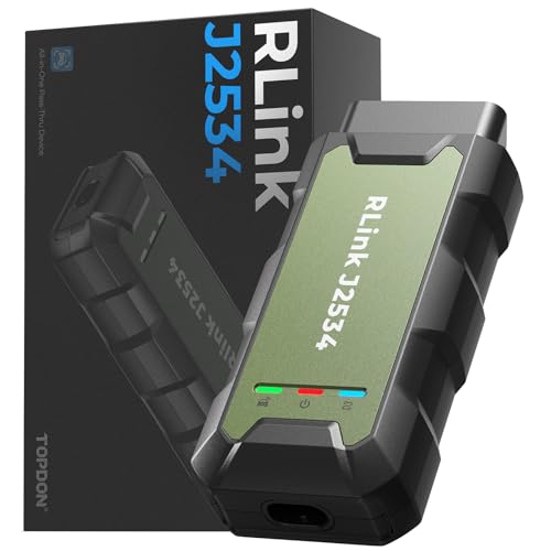
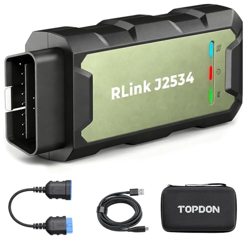
- Advanced VCI Box, Industry-leading J2534 Pass-Thru...
- High-Speed OEM-Level Diagnostics & Programming: Unlock true...
- Coverage for 17 Car Brands & Ultra Reliability: Works...
- User-Friendly RLink Platform & Expert Support: TOPDON’s...
- 6.6 ft USB-C Cable & Portable Storage Case: The RLink J...
Last update on 2026-06-23 / Affiliate links / Images from Amazon Product Advertising API
If the PDF is very large, it may not load in the preview below.
Some older TSBs had multiple PDFs — visit the NHTSA Website to view all PDFs.
If the TSB PDF does not show, download or view it on the NHTSA Website.
Click on the (+) Plus Sign
Then Click on Associated Document(s)
Search NHTSA Database for Recalls
Search NHTSA Database for Vehicle Investigations
View Latest Vehicle Investigations
Search NHTSA Database for Vehicle Complaints
View Latest Vehicle Complaints
TSB/Document ID: ENP-729
Replacement Service Bulletin Number:
MFR Communication Date: 2020-06-03
MFR Internal Campaign ID/Software Version:
Communication Type: Service Bulletin/Repair Instructions
NHTSA Components: EQUIPMENT ADAPTIVE/MOBILITY
MFR Component System:
MFR Component Subsystem:
Previous TSB | Next TSB |

- [Notice] When you receive a used device, it may be a customer return resold by Amazon without inspection. You can exchange it for a new one through Amazon. As this situation is unavoidable, we sincerely apologize. For any issues, contacting us via Amazon's "Messages" is the best way. THINKSCAN 689BT Bidirectional Scan Tool Can Be Used Immediately After It is Turned On, Without Complicated Registration Process, Which is More Convenient & Quick.
- Full Bi-Directional Control & 3000+ Active Tests: Take control and test components like actuators, fuel injectors, relays, and cooling fans in real time. You’ll quickly see if the problem is in the part itself or the control module — saving you hours of guesswork and frustrating trial-and-error.
- Advanced ECU Coding Capabilities: Handle module matching and hidden feature activation with confidence. When you replace an ECU or want to customize settings, this obd2 scanner diagnostic bi directional tool gives you the professional-level capabilities you need without the dealership price tag.
- 34+ Useful Reset and Maintenance Functions: Complete everyday service tasks smoothly with a wide range of helpful reset and maintenance functions. Whether you’re keeping up with regular upkeep or tackling a specific job, this scanner makes maintenance simpler and less stressful for both DIYers and pros.
- Comprehensive Full System Diagnostics: Diagnose every major system — Engine, Transmission, ABS, SRS, TPMS, and more — all in one place. Finally stop wondering if you’re missing something important; get the full picture and clear codes with ease.
Last update on 2026-07-02 / Affiliate links / Images from Amazon Product Advertising API

- Top Reasons to Choose the D7S OBD2 Scanner: XTOOL D7S car scan tool, an upgrade of XTOOL D7, offers comprehensive features for automotive technicians, workshops, and DIY enthusiasts 1. Upgraded Hardware: 2+64GB memory, rear camera, intuitive interface, foldable bracket 2. Complete Diagnostics: FCA
 Autoauth, OE-level all system scan, 39+ maintenance services, 4K+ bidirectional, CANFD/DoIP protocol 3. Advanced Capabilities: ECU c0ding, PMI functions 4. Wide Compatibility: Support 10,000+ models, covering 99% vehicle brands 5. Multi-language: Available in 22+ languages, No IP Restrictions 6. 3-Year Updates: Save 300 bucks on software updates for the latest features and optimizations
 - 2026 Upgraded D7S Car Scanner Features: The newly 2026 D7S V2.0 scanner for car brings exciting features for advanced vehicle diagnostics and enhanced user experience 1. FCA AutoAuth: Now supports FCA SGW module for Chrysler, for Jeep, for Dodge (2018+), for Fiat (2017+), enabling faster vehicle communication without gateway restrictions 2. PMI (Offline ECU Pr0gramming): Allows for Ford, for Lincoln, and for Mazda ECU pr0gramming for new modules 3. Optimized Diagnostic Report 2.0: Personalized reports with logos and customer info for auto shops. Note: Compatibility varies by cars, please check before order
- 39+ Services/Resets/Adaptations/Relearns/Calibrations: XTOOL D7S full system car scanner diagnostic tool tackles 99% of common car issues through its 36+ special functions, including Oil Reset, EPB, SAS, BMS, Throttle Reset, Injector C0ding, ABS Bleed, TPMS Reset, Power Balance, etc and also covers specific-vehicle functions like Crank Sensor Relearn, ABS Initialization, Cylinder Power Balance, Fuel Trim Reset, Idle Relearn etc. This car diagnostic scanner enhances efficiency, making repairs and maintenance hassle-free. Tip: DO NOT for All vehicles, please check compatibility first
- Cost-effective ECU C0ding Scan Tool for Specific Brands: Enhance your vehicle's performance with XTOOL D7S! This obd2 scanner all systems bidirectional offers advanced capabilities at an affordable price, supports online for BMW, for Benz and offline for BENZ, for MIT, along with PMI functions for Ford, for Mazda, and for Lincoln. Ideal for technicians and DIY enthusiasts, this automotive scanner diagnostic tool optimizes vehicle performance and enhances the driving experience. Note: Not for all cars and modules, please send car VIN to check the compatibility before purchase
- OE All System Diagnostic & 8 Pids Graphing: XTOOL D7S is a comprehensive all system bi directional obd2 scanner that delivers dealer-level diagnostics, completely controlling over your vehicle’s performance and health. This automotive scan tool can read and clear DTCs, view live data and ECU information, retrieve freeze frames, and perform active tests and full obd2 functions. This bi-directional scan tool can can identify your vehicle's make, model, and year information with just one click and show up to 8 PIDs live data with options for CSV viewing, playback, and recording for in-depth analysis. It is easy-to-use for both professionals and beginners, helping pinpoint issues efficiently
Last update on 2026-06-30 / Affiliate links / Images from Amazon Product Advertising API

- 【✅Compared to BOSSCOMM IF742, IF745 Offers Full-System Diagnostics】The BOSSCOMM IF745 car diagnostic scanner is an upgraded model of IF742. In addition to supporting all OBD2 Code Reader functions and 6 reset options (ABS/EPB/SAS/BMS/Oil/Throttle), it expands diagnostics from 4 systems (Check Engine/ABS/SRS/Transmission) to vehicle All systems, including Steering, Suspension, and Body Electronics. This provides deeper, more comprehensive diagnostic capabilities.
- 【✨10 OBD2 Functions】The BOSSCOMM IF745 scan tool’s DTC Lookup instantly translates fault codes into user-friendly explanations, its I/M Readiness feature streamlines emissions testing with a single tap, and Freeze Frame lets you pinpoint the exact moment of a fault for in-depth root-cause diagnosis. Combined with a live data dashboard and advanced diagnostics (O2S, OBMon, EVAP), it delivers comprehensive insights for confident troubleshooting.
- 【✨Deep Diagnostics for All Vehicle System Modules】Beyond code reading/clearing and ECU information retrieval, our all-in-one data stream feature lets you inspect all current fault codes and their locations across the vehicle’s systems. This vehicle code reader helps you turn off dashboard warning lights and perform a comprehensive self-check of your car at home—no more back-and-forth trips to the repair shop or hefty inspection fees.
- 【✨6 Essential Resets: ABS Bleeding, Oil, EPB, SAS, Throttle, BMS】The BOSSCOMM IF745 obd2 scanner diagnostic tool swiftly purges air from brake lines to restore braking sensitivity, fine-tunes maintenance cycles to eliminate false alerts, resolves parking brake issues with one-click control, recalibrates steering sensors for stability, optimizes engine idling/acceleration for smoother performance, and deeply resets battery systems to extend lifespan and range via precise parameter adjustments.❗NOTE: Does NOT support bidirectional control, coding, or programming.
- 【✨10,000+ Car Models, AutoVIN, 13 Languages】The BOSSCOMM IF745 vehicle scanner diagnostic tool covers 73+ global car brands and offers support in 13 languages, making it perfect for DIYers, auto mechanics, or as a thoughtful gift. With a single-click AutoVIN feature, it instantly retrieves vehicle serial numbers, streamlining diagnostics for users globally. This adaptable tool balances user-friendliness with precision, catering to both personal and professional requirements.✅Unsure about compatibility? Compatibility will vary on vehicles' model and year, pls reach us via 📧 [email protected] 📧 before purchase.
Last update on 2026-07-02 / Affiliate links / Images from Amazon Product Advertising API
This product presentation was made with AAWP plugin.