
NHTSA ID Number: 10133203
Manufacturer Communication Number: NTB17-039e
TSB/Document Date: 2018-04-16
Summary
PATHFINDER, ALTIMA, MAXIMA, MURANO AND QUEST; CVT JUDDER AND DTC P17F0 OR P17F1 STORED This bulletin applies only to vehicles equipped with a V6 engine. This bulletin has been amended to add Quest to Applied Vehicles and information related to Quest on pages 25, 100, 102, 103 and 105. Please discard previous versions of this bulletin. IMPORTANT: You must read the entire bulletin to properly perform this repair.
Fitting bolt
Figure 24B
b. Remove the three oil pump Allenhead bolts, and remove the oil pump
(Figure 25B).
NOTE:
o Do NOT discard the Allen-head
bolts. Bolts will be re-used.
o New oil pump will be installed
at later steps.
Figure 25B
18. Remove CVT fluid filter as follows:
a. Remove the four (4) bolts and then
remove the CVT fluid filter cover
(Figure 26B).
NOTE: Bolts will be reused.
CVT fluid filter cover
Figure 26B
26/105
NTB17-039e
Fluid filter
b. Remove the CVT fluid filter with
grommet seal and O-ring seal
(Figure 27B).
Discard the oil filter and seal. They
will be replaced.
O-ring seal
Figure 27B
Grommet
Grommet is fitted to the bottom
end of the filter and is included
with replacement filter
(Figure 28B).
Figure 28B
27/105
NTB17-039e
Clean the CVT case surfaces
1. Thoroughly clean the mating surfaces of the CVT case and Torque Converter Housing.
A plastic scraper can be used.
CAUTION:
DO NOT use sanding discs, similar abrasive tools, or metal blades.
Use brake spray or equivalent solvent and lint-free towels only.
Make sure brake spray or solvents used are compatible with local regulations.
Avoid debris entering into the inside of the CVT.
Make sure rust and debris have been cleaned off of dowel pins and receiving
holes (Figure 1C).
2. Clean the dowel pins and dowel pin receiving holes of any rust or debris with emery
cloth (Figure 1C).
NOTE: Use small wire brush or similar tool at the inside surface of dowel pin holes. DO
NOT SCRAPE CVT CASE mating surfaces.
Clean dowel pin
receiving holes
Clean
dowel pin
Figure 1C
28/105
NTB17-039e
Clean the Oil Passages in the CVT Case, Oil Pump Cover, and CVT Filter Area
In the following steps:
Brake cleaner and compressed air will be used to clean out oil passages in the CVT
assembly.
Make sure the brake cleaner or solvents are compatible with local regulations.
WARNING: Wear eye / face protection when using compressed air and cleaning
fluids.
CAUTION:
Regulate air pressure up to a maximum of 75 PSI.
Do not use water-based (aqueous) cleaners.
1. Clean the area where the CVT fluid filter
fits (Figure 2C).
Clean within
this area
Make sure the old filter grommet seal
is removed.
2. Clean the fluid passages to and from the
filter (Figure 2C).
Fluid
passages
Figure 2C
3. Clean filter cover (Figure 3C).
Figure 3C
29/105
NTB17-039e
4. Spray brake clean in all oil passages of the CVT case where shown in Figure 4C and
Figure 5C.
5. Remove lip seal if not already removed.
6. Apply compressed air in the same passages.
NOTE:
Do not stand in front of the passages while using compressed air.
Do not spray brake clean directly into clutch pack.
Lip seal
Figure 4C
Apply cleaner, and then
75 PSI maximum air
pressure in these
passages.
Air pressure comes
out these passages.
Figure 5C
30/105
NTB17-039e
New Oil Pump Installation
1. Install the new oil pump using three (3)
original Allen-head bolts (Figure 1D).
NOTE:
Finger tighten the Allen-head bolts at
this time.
IMPORTANT: A Parts Kits Reference Table
is provided on page 102.
Use the check off column on the left
to ensure the correct new part is
installed at each step.
Figure 1D
Attach this to the repair order.
Fitting bolt
O-ring
2. Place new O-ring on the fitting bolt, and
coat with CVT fluid (Figure 2D).
Figure 2D
3. Install the fitting bolt finger tight
(Figure 3D).
Fitting
bolt
Figure 3D
31/105
NTB17-039e
4. Torque the three (3) Allen head bolts and fitting bolt.
Allen head bolt torque: 17.6 – 20.6 N•m (1.79 – 2.1 kg-m, 13.0 – 15.2 ft-lb)
Fitting bolt torque: 26.0 – 30.0 N•m (2.65 – 3.06 kg-m, 19.2 – 22.1 ft-lb)
5. Install the original snap ring (Figure 4D).
Snap ring
Figure 4D
6. Install the CVT fluid filter and components (Figure 5D).
Install a new filter with grommet (one part).
Install a new O-ring.
Confirm that all components and areas where components fit are thoroughly clean.
Apply CVT fluid to the grommet seal and O-ring before installing.
Install the filter cover.
Bolt torque 4.2 N•m (0.43 kg-m, 37.2 in-lb.)
Fluid filter
O-ring seal
CVT fluid filter cover
Figure 5D
32/105
NTB17-039e
Replace the Side Cover – Pulleys and Chain (sub-assembly)
1. Temporarily install the dummy cover with
3 bolts, finger tight (Figure 1E).
IMPORTANT:
Do not install any thrust bearing to
the clutch assembly bore at this
time.
If cover does not seat flush see
trouble shooting The Dummy
Cover Will Not Sit Flush on
page 98.
Bolts
Dummy cover
Figure 1E
2. Temporarily install the converter housing
onto the CVT case with three bolts finger
tight (Figure 2E).
IMPORTANT:
When fitting the CVT case
surfaces, DO NOT use the bolts to
draw in the case halves.
Make sure the case surfaces are
flush, and have no gaps prior to
installing the bolts.
Bolts
Converter housing
Figure 2E
33/105
NTB17-039e
3. Flip the CVT case so that the converter
housing faces down and side-cover faces
up.
Lifting fixture J-51595 can be used for
this step. This tool is not shown in
Required Tools / Materials.
Manual shaft
CAUTION:
Do not hit the manual shaft (Figure
3E) while flipping the CVT; the
manual shaft protrudes past the CVT
case. Use a plastic / wooden block to
support as needed.
Figure 3E
Note the location of the terminal
connector harness. Do not pinch the
terminal connector harness between
the CVT case and work bench or
supporting blocks.
4. Rotate the primary pulley by hand to
check the pulleys rotational
characteristics.
Rotate the primary
pulley by hand
IMPORTANT:
Remember the pulley’s rotational
characteristics. This will be used
as a reference after the new side
cover-pulleys and belt subassembly (sub-assembly) have
been installed.
Figure 4E
This will be used as a reference
later in the procedure to determine
if the sub-assembly installation is
successful or not.
WARNING: Do not place fingers between
the pulley and the CVT case.
Do not place fingers
under pulley
Figure 5E
34/105
NTB17-039e
NOTE: When working with sub-assembly install, uninstall, and bracket attachment, it is
critical that CVT and sub-assembly are level. If not level, the pulleys and bearings can sit
slightly at an angle and will hinder installation.
5. Remove the nineteen (19) side cover
bolts (Figure 6E).
Loosen the bolts with hand tools only.
These bolts will be replaced with new
ones and will not be reused.
Figure 6E
6. Remove the six (6) pulley bracket bolts.
Bolts will be reinstalled to the original
pulley and belt sub-assembly.
Figure 7E
35/105
NTB17-039e
7. Attach universal Lifting Fixture J-52082 with spacers J-52082-2 to the side cover as
shown in Figure 8E.
NOTE: Install and tighten by hand only.
a. Loosen all of the wing-nut bolts on the Lifting Fixture.
b. Confirm that three (3) spacers (# J-52082-2) are present between the longer legs
and triangle bracket as shown in Figure 8E.
c. Install the Lifting Fixture to the CVT case at the six (6) bolt holes shown in Figure 7E
on page 35.
d. Tighten the two (2) joint to triangle brackets.
e. Tighten the wing-nut bolts on the Lifting Fixture finger tight.
CAUTION: Do not cross thread the bolts when attaching to the CVT side
cover.
(3) Spacers
(# J-52082-2)
Triangle
bracket
Lifting Fixture J-52082
Longer legs
Triangle
bracket joint
Figure 8E
8. Install the two CVT Assembly Guide Pins (J-51959 - Guide Pins) as shown in Figure 9E
and Figure 10E.
The Guide Pins must be located next to the dowel pins.
Guide Pin
Guide Pin
Guide Pin
Dowel Pin
Pins
Dowel Pin
Figure 9E
Figure 10E
36/105
NTB17-039e
9. Raise the Lifting Fixture so that the CVT assembly weight is mostly supported by the
Lifting Fixture and just slightly raised off of the work surface (using Tool #: J-52082).
10. Loosen the side cover with a slide hammer at the three points shown in Figure 11E.
Rotate between the 3 locations on the side cover until the CVT case separates from
the sub-assembly; this can take more than one rotation to loosen sealant.
CAUTION: DO NOT use a pry-bar, chisel, etc. to separate the side cover from
the CVT case.
NOTE: Apply rust penetrant to the two dowel pins as needed.
The following Figure is for reference only and does not show the lifting device attached.
Tool location
marks
Dowel
pin
Dowel
pin
Figure 11E
11. Raise the lifting fixture to remove the
“side cover with pulleys and chain subassembly” (sub-assembly) from the CVT
case (Figure 12E) and set aside.
CAUTION: Make sure the primary speed
sensor is removed from the subassembly.
Speed sensor will be reused.
DO NOT discard speed sensor.
This sub-assembly will not be
reused.
12. Remove the lifting Fixture from the subassembly and replace all six (6) original
bolts.
37/105
Sub-assembly
Figure 12E
CVT case
NTB17-039e
13. Thoroughly clean the mating surfaces of the CVT case (Figure 13E) that the subassembly was just separated from (a plastic scraper can be used).
Clean off dowel pins.
Confirm that dowel pins have remained in the CVT case. If not, remove them from
the sub-assembly and relocate back to the CVT case.
Reinstall guide pins if they were removed during case cleaning.
CAUTION:
DO NOT use sanding discs, similar abrasive tools, or metal blades.
Use brake cleaner or equivalent solvent and lint-free towels only.
Make sure brake spray or solvents used are compatible with local regulations
Avoid debris entering into the inside of the CVT.
Make sure rust and debris have been cleaned off of dowel pins and receiving
holes.
14. Remove the O-ring from the CVT case (Figure 14E).
This O-ring will not be reused.
Mating surfaces
O-ring
Figure 13E
Figure 14E
15. Remove the thrust bearing from the
planetary carrier plate (Figure 15E).
Thrust bearing will be re-used.
DO NOT discard.
CAUTION: If not found on the
planetary carrier plate, the thrust
bearing may still be attached to the
primary pulley.
Thrust bearing
Figure 15E
38/105
NTB17-039e
Shift select lever
16. Rotate the shift select lever counter
clockwise to the “L” range position
(Figure 16E), so that the parking rod is at
its lowest position (Figure 17E).
Figure 16E
Parking rod
Figure 17E
17. Remove the six (6) bolts from the new
sub-assembly and then remove their Orings.
These bolts will be reused.
These O-rings will not be reused.
Lifting Fixture
18. Attach Lifting Fixture to the new subassembly, and then raise sub-assembly
out of shipping box.
CAUTION: Do not cross thread side
cover holes when installing the Lifting
Fixture. Always start bolts by hand.
Sub-assembly
Figure 18E
39/105
NTB17-039e
19. Install the original thrust bearing onto the primary pulley of the new sub-assembly
(Figure 19E).
CAUTION: The thrust bearing has two different sides. Reference Figure 19E for correct
bearing orientation.
Apply a thin layer of petroleum jelly or equivalent to the original thrust bearing to
hold it in place on the primary pulley.
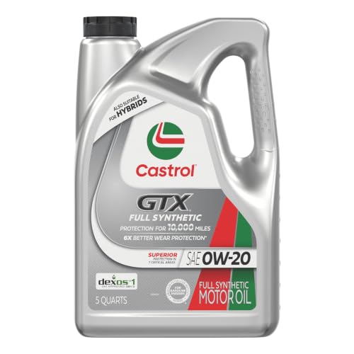
- 6X better wear protection on critical engine parts than...
- 1.3X better sludge protection than industry standards*
- 3X Stronger against viscosity breakdown than leading full...
- Protection for 10,000 miles between oil changes
- Meets or exceeds the following specifications: API SP/SN...

If the PDF is very large, it may not load in the preview below.
Some older TSBs had multiple PDFs — visit the NHTSA Website to view all PDFs.
If the TSB PDF does not show, download or view it on the NHTSA Website.
Click on the (+) Plus Sign
Then Click on Associated Document(s)
Search NHTSA Database for Recalls
Search NHTSA Database for Vehicle Investigations
View Latest Vehicle Investigations
Search NHTSA Database for Vehicle Complaints
View Latest Vehicle Complaints
TSB/Document ID: NTB17-039e
Replacement Service Bulletin Number:
MFR Communication Date: 2018-03-05
MFR Internal Campaign ID/Software Version:
Communication Type: Service Bulletin/Repair Instructions
NHTSA Components: EQUIPMENT:OTHER:OWNERS/SERVICE/OTHER MANUAL
MFR Component System:
MFR Component Subsystem:
Previous TSB | Next TSB |

- [Notice] When you receive a used device, it may be a customer return resold by Amazon without inspection. You can exchange it for a new one through Amazon. As this situation is unavoidable, we sincerely apologize. For any issues, contacting us via Amazon's "Messages" is the best way. THINKSCAN 689BT Bidirectional Scan Tool Can Be Used Immediately After It is Turned On, Without Complicated Registration Process, Which is More Convenient & Quick.
- Full Bi-Directional Control & 3000+ Active Tests: Take control and test components like actuators, fuel injectors, relays, and cooling fans in real time. You’ll quickly see if the problem is in the part itself or the control module — saving you hours of guesswork and frustrating trial-and-error.
- Advanced ECU Coding Capabilities: Handle module matching and hidden feature activation with confidence. When you replace an ECU or want to customize settings, this obd2 scanner diagnostic bi directional tool gives you the professional-level capabilities you need without the dealership price tag.
- 34+ Useful Reset and Maintenance Functions: Complete everyday service tasks smoothly with a wide range of helpful reset and maintenance functions. Whether you’re keeping up with regular upkeep or tackling a specific job, this scanner makes maintenance simpler and less stressful for both DIYers and pros.
- Comprehensive Full System Diagnostics: Diagnose every major system — Engine, Transmission, ABS, SRS, TPMS, and more — all in one place. Finally stop wondering if you’re missing something important; get the full picture and clear codes with ease.

- Top Reasons to Choose the D7S OBD2 Scanner: XTOOL D7S car scan tool, an upgrade of XTOOL D7, offers comprehensive features for automotive technicians, workshops, and DIY enthusiasts 1. Upgraded Hardware: 2+64GB memory, rear camera, intuitive interface, foldable bracket 2. Complete Diagnostics: FCA
 Autoauth, OE-level all system scan, 39+ maintenance services, 4K+ bidirectional, CANFD/DoIP protocol 3. Advanced Capabilities: ECU c0ding, PMI functions 4. Wide Compatibility: Support 10,000+ models, covering 99% vehicle brands 5. Multi-language: Available in 22+ languages, No IP Restrictions 6. 3-Year Updates: Save 300 bucks on software updates for the latest features and optimizations
 - 2026 Upgraded D7S Car Scanner Features: The newly 2026 D7S V2.0 scanner for car brings exciting features for advanced vehicle diagnostics and enhanced user experience 1. FCA AutoAuth: Now supports FCA SGW module for Chrysler, for Jeep, for Dodge (2018+), for Fiat (2017+), enabling faster vehicle communication without gateway restrictions 2. PMI (Offline ECU Pr0gramming): Allows for Ford, for Lincoln, and for Mazda ECU pr0gramming for new modules 3. Optimized Diagnostic Report 2.0: Personalized reports with logos and customer info for auto shops. Note: Compatibility varies by cars, please check before order
- 39+ Services/Resets/Adaptations/Relearns/Calibrations: XTOOL D7S full system car scanner diagnostic tool tackles 99% of common car issues through its 36+ special functions, including Oil Reset, EPB, SAS, BMS, Throttle Reset, Injector C0ding, ABS Bleed, TPMS Reset, Power Balance, etc and also covers specific-vehicle functions like Crank Sensor Relearn, ABS Initialization, Cylinder Power Balance, Fuel Trim Reset, Idle Relearn etc. This car diagnostic scanner enhances efficiency, making repairs and maintenance hassle-free. Tip: DO NOT for All vehicles, please check compatibility first
- Cost-effective ECU C0ding Scan Tool for Specific Brands: Enhance your vehicle's performance with XTOOL D7S! This obd2 scanner all systems bidirectional offers advanced capabilities at an affordable price, supports online for BMW, for Benz and offline for BENZ, for MIT, along with PMI functions for Ford, for Mazda, and for Lincoln. Ideal for technicians and DIY enthusiasts, this automotive scanner diagnostic tool optimizes vehicle performance and enhances the driving experience. Note: Not for all cars and modules, please send car VIN to check the compatibility before purchase
- OE All System Diagnostic & 8 Pids Graphing: XTOOL D7S is a comprehensive all system bi directional obd2 scanner that delivers dealer-level diagnostics, completely controlling over your vehicle’s performance and health. This automotive scan tool can read and clear DTCs, view live data and ECU information, retrieve freeze frames, and perform active tests and full obd2 functions. This bi-directional scan tool can can identify your vehicle's make, model, and year information with just one click and show up to 8 PIDs live data with options for CSV viewing, playback, and recording for in-depth analysis. It is easy-to-use for both professionals and beginners, helping pinpoint issues efficiently

- 【✅Compared to BOSSCOMM IF742, IF745 Offers Full-System Diagnostics】The BOSSCOMM IF745 car diagnostic scanner is an upgraded model of IF742. In addition to supporting all OBD2 Code Reader functions and 6 reset options (ABS/EPB/SAS/BMS/Oil/Throttle), it expands diagnostics from 4 systems (Check Engine/ABS/SRS/Transmission) to vehicle All systems, including Steering, Suspension, and Body Electronics. This provides deeper, more comprehensive diagnostic capabilities.
- 【✨10 OBD2 Functions】The BOSSCOMM IF745 scan tool’s DTC Lookup instantly translates fault codes into user-friendly explanations, its I/M Readiness feature streamlines emissions testing with a single tap, and Freeze Frame lets you pinpoint the exact moment of a fault for in-depth root-cause diagnosis. Combined with a live data dashboard and advanced diagnostics (O2S, OBMon, EVAP), it delivers comprehensive insights for confident troubleshooting.
- 【✨Deep Diagnostics for All Vehicle System Modules】Beyond code reading/clearing and ECU information retrieval, our all-in-one data stream feature lets you inspect all current fault codes and their locations across the vehicle’s systems. This vehicle code reader helps you turn off dashboard warning lights and perform a comprehensive self-check of your car at home—no more back-and-forth trips to the repair shop or hefty inspection fees.
- 【✨6 Essential Resets: ABS Bleeding, Oil, EPB, SAS, Throttle, BMS】The BOSSCOMM IF745 obd2 scanner diagnostic tool swiftly purges air from brake lines to restore braking sensitivity, fine-tunes maintenance cycles to eliminate false alerts, resolves parking brake issues with one-click control, recalibrates steering sensors for stability, optimizes engine idling/acceleration for smoother performance, and deeply resets battery systems to extend lifespan and range via precise parameter adjustments.❗NOTE: Does NOT support bidirectional control, coding, or programming.
- 【✨10,000+ Car Models, AutoVIN, 13 Languages】The BOSSCOMM IF745 vehicle scanner diagnostic tool covers 73+ global car brands and offers support in 13 languages, making it perfect for DIYers, auto mechanics, or as a thoughtful gift. With a single-click AutoVIN feature, it instantly retrieves vehicle serial numbers, streamlining diagnostics for users globally. This adaptable tool balances user-friendliness with precision, catering to both personal and professional requirements.✅Unsure about compatibility? Compatibility will vary on vehicles' model and year, pls reach us via 📧 [email protected] 📧 before purchase.
This product presentation was made with AAWP plugin.