
NHTSA ID Number: 10117298
Manufacturer Communication Number: IK1900198
TSB/Document Date: 2017-09-08
Summary
MaxxPower No Idle Battery-Powered A/C System Diagnostic Guide; models equipped with feature 16UZL
and at louvers and recirculation grill. Check pressure switch, thermal
limit and / or discharge temperature sensor. See appendix D, F and I.
Unit Blows Cold Air, But
Low Airflow
1. Check all duct work connections
2. Air flow restricted
3. Evaporator blower motor inoperative
1. Make sure all ducts are connected, sealed and secure
2. Check for airflow at louvers and recirculation grill.
3. Check evaporator blower motor and linear power module. See
appendix M.
Unit Runs Correctly, But
Less Than Expected Run
Time
1. Ground terminal(s).
2. Batteries weak or not charged correctly
3. High amperage draw
1. Inspect and tighten ALL connections.
2. Check batteries for condition and state of charge. See appendix A.
3. Use DC Ammeter to check amps when running. Excessive amperage
could signal compressor or internal component issue. Amperage
ranges 40 to 75 depending on conditions.
Unit is Noisy or Vibrates
1.
2.
3.
4.
Evaporator Blower motor.
Condenser fan motor.
Compressor mounting.
Compressor internal.
1.
2.
3.
4.
Check evaporator blower. See appendix M.
Check Condenser fan. See appendix L.
Check rubber compressor mounts. See appendix N.
If rubber compressor mounts check out acceptable, and compressor
vibrates excessively, call Navistar Dealer.
ENGINE RUNNING
Blower Motor Runs - But
Does Not Blow Cold Air
(Unit will be operating on
Engine system, not the
MaxxPower system)
1. Airflow blockage
2. Blend door
3. Engine driven system charge level.
1. Clear any blockage from recirculation filter, grill or louvers. Also check
condenser inlet and outlet for restriction (outside truck).
2. Check blend door operation. See appendix H.
3. Check refrigeration charge level and engine driven compressor.
Appendix
A. Battery Condition and Performance:
• Battery Voltage is critical for system operation. Special attention should be given to both sets of batteries.
• Attention: Poor quality batteries or a weak alternator will have a negative impact on MaxxPower unit run time. Always maintain the best possible
batteries and charging system. Standard alternator 320 Amp.
• Load test and maintain batteries as required by the manufacturer.
B. LED Control Display and COOL - No Idle Switch Testing: Attention! Conduct the initial test with ENGINE OFF/ KEY OFF AND
BRAKES SET!!!
• Turn the MaxxPower unit on by pressing the Cool No/Idle momentary switch.
• Pushing the COOL – No Idle momentary switch will signal the MaxxPower unit to start. The led light in the switch will illuminate. At this time the display
will also light up and the MaxxPower unit will start at its default setting and will indicate this by the rows of bars showing on the display. Pushing the
temperature or blower speed buttons will increase or decrease these settings higher or lower.
• If you are pushing the COOL – No Idle momentary switch and the unit does NOT start, check for 12 volts at the switch terminals. Wire (vbat) should
have 12 volts. This voltage comes from the 10 amp System Controller Fuse, through pin A1 of the 30 pin harness connector(5205), then to pin 32 of
the System Controller connector. Pushing the COOL No Idle momentary switch sends power from the switch, through pin B13 of the 30 pin harness
connector(5205) then to pin 6 of the System Controller connector.
• If you have 12 volts at pin 6 on the System controller and the unit does not start, the System Controller is defective.
• If you have 12 volts at pin 6 and the unit starts but the display does not come on, check for proper voltage at the LED display, pin connection 7 (pos)
coming from the Blower Motor Fuse through pin A11 of the 30 pin harness connector(5205). Use pin 8 (neg) at the display, coming from chassis
ground, through pin A2 of the 30 pin harness connector(5205), to check for this voltage. You should have 12 volts. Now check the dimmer to panel
https://evalue.internationaldelivers.com/service_kb/DocTool/ArticleViewer.aspx?ControlID... 7/1/2014
IK1900198 - MaxxPower No Idle Battery-Powered A/C System Diagnostic Guide.
Page 10 of 17
signal, pin 15 on the display. You should have 1.5V at the controller from pin 18 of the System Controller passing through pin A12 of the 30 pin harness
connector(5205). If you do not have the dimmer signal you may have a bad system controller or harness.
• After a few seconds, the display will dim and the bars for temperature and blower speed will not show. As soon as you push the increase or decrease
buttons the display will wake up.
C. Relay Testing:
• With relay unplugged, confirm there is 12 VOLT on the sockets where 85 and 30 relay terminals are connected.
• If you do not have 12 VOLT here check fuses, wiring and battery connections.
• Now, with relay unplugged, check across terminals 85 and 86 on the relay, using an OHM meter. You should have 80 to 100 ohms.
◦ This is measuring the resistance through the relay coil. If you do not, replace relay.
• Starting the MaxxPower system…as soon as you turn the COOL – No Idle switch on, terminals 86 on the Compressor Relay and Condenser Fan relay
become connected to ground internally on the System Controller pin 3. Also, the Blower Motor relay terminal 86 connects to ground internally at pin 2 on
the system controller. When this happens the relays will pull in the contacts and allow voltage through the relays. You should now have 12 VOLT
passing through the relays on spade terminals 87 of the relays. This provides power to the Compressor fuse, Blower Motor fuse, and Condenser Fan
fuse, continuing to the evaporator blower motor, condenser fan and the compressor controlling section of the Compressor Controller Assembly.
• With relay plugged in: TURN THE UNIT ON.
• If you do not have 12 VOLT on terminal 87, check across terminals 85 (+) an 86 (). You should have 12 VOLT. If you do not, you may have a defective
harness or system controller. If you have 12 VOLT here and do not have 12 VOLT on terminal 87 your relay is defective. The internal coil of the relay is
energized but the contacts are not closing. Replace the relay.
• If you have 12 VOLT on terminal 87 and the compressor, condenser fan or evaporator blower does not run you could have a defective component such
as evaporator blower, condenser fan or compressor controller. See testing Evaporator Blower Motor-Appendix M, Condenser Fan-Appendix L,
Compressor / ControllerAppendix K.
D. Pressure Switch Testing:
• You must remove the top compressor controller cover of the MaxxPower unit to access the switch.
• The brazed switch is not removable.
• This switch is normally closed. When the unit is off for a few minutes, unplug the System Controller and check between pins 28 and 17, you should
always have continuity. If you do not, you may have a broken wire, bad connection, high pressure situation or defective switch. If the pressure, harness
and connections are ok, the MaxxPower unit will have to be replaced. Call Navistar.
E. Check continuity across fuse body (fuse does not look blown)
• Remove fuse from fuse holder. Using a meter, check for continuity across the fuse. You can check for voltage at and through the fuse using a dc volt
meter, with the fuse installed.
F. Discharge Temperature Sensor/Freeze Switch Testing:
•
•
•
•
•
Location: Top of unit, at evaporator blower outlet.
IF THE SENSOR OR CIRCUIT HAS A SHORT OR OPEN a fault code will be seen on J1939.
IF THE SENSOR IS DEFECTIVE THE COMPRESSOR WILL NOT OPERATE!
The freeze switch is a temperature sensor. To verify the condition you will need a Volt/OHM meter.
If a freeze condition occurs, the unit will stop the compressor. If the freeze condition leaves, the compressor will restart and the MaxxPower unit will
continue to run.
• Check resistance (ohms) value at the system controller with the 32 pin connector disconnected. You should read a resistance across terminals 26 (pos)
and17 (neg) within the range listed in the Discharge Sensor / Air inlet sensor temp chart found in the "Circuit Diagrams" section of the iKNow article. If
you cannot read the resistance, check at the sensor connection. If you read the resistance here, and it’s within the range allowed, you have a defective
harness.
• If you cannot read the resistance or it is not within the given range, your sensor is defective.
G. Inlet Temperature Sensor:
•
•
•
•
IF THE SENSOR OR CIRCUIT HAS A SHORT OR OPEN a fault code will be seen on J1939.
IF THE SENSOR IS DEFECTIVE THE unit will default to a cab temperature of 70 F and operate accordingly.
This sensor monitors the return air temperature.
Check resistance (ohms) value at the system controller with the 32 pin connector disconnected. You should read a resistance across terminals 24 (pos)
and 17 (neg) within the range listed in the Discharge Sensor / Air inlet sensor temp chart found in the "Circuit Diagrams" section of this article. If you
cannot read the resistance, check at the sensor connection. If you read the resistance here, and it’s within the range allowed, you have a defective
harness.
• If you cannot read the resistance or it is not within the given range, your sensor is defective.
H. Blend Door Actuator:
• Physical inspection of the door, can be seen through the top of the unit by removing the evaporator blower.
• This actuator motor drives the blend door.
• When in the heat mode the blend door will direct recycled air through the heater core as directed by the Digital Control Panel in order to maintain a
preset temperature. The Espar Hydronic coolant heater will provide a constant flow of heated coolant through the heater core for internal bunk heat as
well as engine heat.
• First, check for 12 volts (pos) on terminal 10 of the actuator, coming from fuse F4. Ground is terminal 7 on the actuator. If you do not have power here
you may have a defective harness or system controller.
• If you have power here, check for the move signal at pin 8 on the actuator, coming from pin 25 of the system controller. This is a variable signal ranging
from 11 volts at max cold to 0 volts full heat. If this voltage is not there or the voltage does not change, you have a defective system controller or
harness. If this voltage is present and variable, and the door does not operate, you may have a defective actuator or inoperative blend door.
I. Compressor Thermal Limit Switch:
• You must remove the top compressor controller cover of the MaxxPower unit to access the switch.
• This device is a normally closed switch. If the compressor gets too hot, the thermal limit switch will open and the compressor will stop. Checking with a
meter you should always have continuity between the two terminals when it is cool.
https://evalue.internationaldelivers.com/service_kb/DocTool/ArticleViewer.aspx?ControlID... 7/1/2014
IK1900198 - MaxxPower No Idle Battery-Powered A/C System Diagnostic Guide.
Page 11 of 17
J. System Controller:
• Do not attempt to test the controller until you have completely eliminated all other possibilities.
• The MaxxPower System controller is the device that stores the operating program for the system and controls most input and output functions. This
controller is powered through the System Controller fuse to pin 32 on the controller. Pin 31 is the ground. If you have 12 volts here, the system controller
is waiting for an input from the COOL or HEAT No Idle switch for start up.
• If you do not have 12 volts here, check fuses F6(Battery Box) and System Controller fuse, also check for chassis ground.
• If you have 12 volts here and the unit will not run, check for the input from the COOL No Idle momentary switch at pin 6 on the system controller. If you
have this 12 volt signal on pin 6 when the switch is depressed (this is a momentary switch) and the unit does not run, check the sensors, pressure
switch, and compressor thermal high limit. Also check battery voltage (LVD). If all safety devices are ok, your controller is defective. Replace the
controller.
K. Compressor Controller:
• This device controls the refrigerant compressor
• When the MaxxPower system is powered up, the compressor controller is waiting for the system to call for conditioned air. Once the system calls for
•
•
•
•
•
conditioned air, the system controller will connect Compressor Relay terminal 86 to ground at pin 3 of the system controller. This will close Compressor
Relay contacts and allow main power through the Compressor Fuse to the compressor controller. Even though main power is sent to this controller, it
will not start the compressor until it receives a speed signal at pin C16 from the System Controller pin 1. Once it has received the speed signal the
compressor controller will start the refrigerant compressor. The compressor will operate as long as the thermal limit on the compressor is closed and the
system continues to call for conditioned air.
Check for 12 VOLT from the 60 amp Compressor Fuse, continuing through the packard connector to the compressor controller. If you have 12 volts
here, check for the speed signal at pin C16. You should have a voltage here ranging from 3.2 on high to 3.9 volts on low. If you have this speed signal,
you should have voltage out on the three wires connected to the compressor.
Disconnect the three wires from the compressor. You will have to remove plastic cap from the top of compressor.
Using a volt meter check each wire, positive on (blue, orange or yellow) negative to battery ground. If you do not have a 6 volt pulse voltage out on each
wire, replace the controller. Pulse voltage means the controller will cycle to each colored wire. You should see the voltage appear and disappear
continuously.
Reconnecting the three wires you must connect blue to A, orange to B, and yellow to C.
If you do have a 6 volt pulse voltage at the compressor and the compressor does not run you have a defective compressor. Call Navistar dealer.
L. Condenser Fan Motor Testing:
• First do a visual inspection of all blower parts.
• For condenser fan location see Navistar documents.
• Turn the MaxxPower unit on; you should have 12 volts across terminals A and B at the condenser fan connector. If you do not have 12 volt at the fan,
check the Condenser Fan Fuse and Condenser Fan Relay. If you have 12 VOLT main power, check for the signal voltage at the condenser fan
connector pin C coming from pin 29 of the system controller. You should have between 3.1 volts on low speed and 4.8 volts on high. If all voltages are
correct, (the plug needs to be connected in order to read the signal voltages) and the fan does not run, it is defective, and needs to be replaced.
• Using a DC ammeter you can check the amperage draw of the blower. Normal amps approx. 6 to 10 Amps max.
• Caution: If attempting to connect blower to an outside power source, internal electronic components are sensitive to arcing or reverse
polarity! Damage will occur!!
M. Evaporator Blower Motor and Linear Power Module Testing:
• First do a visual inspection of all blower parts.
• The evaporator blower speed is controlled by the LPM, Linear Power Module, item I.
• Turn the MaxxPower unit on, you should have 12 volt at the LPM pins 6 (pos) and pin 5 (neg), if you do not, check Blower Motor Fuse and Blower Motor
Relay. If you have 12 VOLT main power, check for the speed signal voltage on the LPM at pin 3 coming from the system controller pin 30. You should
have approx. 4.5V at low speed and approx. 2.5V at high speed. If all of these voltages are correct, (the plug needs to be connected in order to read the
signal voltages) check the output voltage from the LPM pins 1 and 2 going to the blower. You should have approx 6.5V in low and 10.6V in high to the
motor depending on the speed signal from the system controller. If all voltages are correct, reconnect the plug.
• If fan does not run, it is defective, and needs to be replaced.
• Using a DC ammeter you can check the amperage draw of the blower. Normal amps will range from 4 to 10 amps.
• Caution: If attempting to connect blower to an outside power source, internal electronic components are sensitive to arcing or reverse
polarity! Damage will occur!!
N. Compressor Rubber Mounts:
• Visual inspection of the compressor rubber mounts may be necessary if excessive vibration is present. Check for loose mounting nuts. If mounting nuts
and captive studs are Ok, vibration could be from the internal part of the compressor.
Circuit Diagrams
The Bergstrom No-Idle HVAC System uses a Bergstrom harness that connects to the OEM harness. The wiring schematic books will only show the
OEM wiring. The PDF below will outline the OEM wiring and show all the Bergstrom wiring. The wiring shown as "A/C UNIT" is where the OEM and
Bergstrom harnesses meet.
Also note the OEM wiring has standard sleeper HVAC wiring and all other sleeper wiring configurations. Take time to ensure you're looking at the
correct schematic for this system. In the most current schematic book "0000002122" the No-Idle system wiring starts on Ch 12 Pg 15.
• Discharge Sensor / Air inlet sensor temp chart CLICK HERE
• Service Portal Master Service Information CLICK HERE
• MaxxPower HVAC Circuit Diagram (PDF) CLICK HERE
Photos with Call Outs
https://evalue.internationaldelivers.com/service_kb/DocTool/ArticleViewer.aspx?ControlID... 7/1/2014
IK1900198 - MaxxPower No Idle Battery-Powered A/C System Diagnostic Guide.
Page 12 of 17
https://evalue.internationaldelivers.com/service_kb/DocTool/ArticleViewer.aspx?ControlID... 7/1/2014
IK1900198 - MaxxPower No Idle Battery-Powered A/C System Diagnostic Guide.
Page 13 of 17
Parts Information
Part #
Description
Qty.
2614669C1
Sealed Ref System 12V
1
3685807C1
Condenser Fan
1
3695241C1
Temp Sensor
2
3685810C1
System Controller
1
2614670C1
Compressor Controller (Circuit Board)
1
3685818C1
Blend Door
1
3693481C1
LPM
1
3688223C1
Bunk Blower Motor
1
3688228C2
Harness, Heater 12v No-Idle
1
3838206C92
Cable, Battery
1
REPLACMENT OF NEW REFRIGERANT LOOP 2614669C1 MAY ALSO REQUIRE THE REPLACMENT OF THE NEW CLUSTER BLOCK 2614670C1 AS WELL.
Replacing the Cold Loop
The Bergstrom Maxx-Power air conditioning system has a cold loop replacement housing used to replace the non-serviceable air conditioning components. If
the system has lost it's refrigerant, if there is a compressor failure, or damage to the evaporator, condenser, or refrigerant lines, the cold loop will need to be
replaced.
Selecting the Correct Components
MaxxPower units built prior to 7/16/2012 were built with flag terminals on the compressors. Due to product improvements, the terminals were changed to a
cluster block after 7/16/2012. All cold loop service parts are built with the cluster block style compressor. The cluster block style can be identified by it's black
color. The flag style compressor is a purple/ blue color. The compressor controller is not compatible between the two units. If the vehicle was built with the flag
type compressor (purple/ blue), when replacing the cold loop, the compressor controller will also need to be replaced.
https://evalue.internationaldelivers.com/service_kb/DocTool/ArticleViewer.aspx?ControlID... 7/1/2014
IK1900198 - MaxxPower No Idle Battery-Powered A/C System Diagnostic Guide.
Page 14 of 17
If when removing the old cold loop it is found that the compressor in the unit is the cluster block style (black), the compressor controller should
not be replaced.
If you have a failed compressor controller with the Purple (Blue) Compressor, you will need to replace the cold loop with the compressor
controller.
Service Parts Based on Serial Number Prefix
The serial number can be found on a tag of the Maxx Power HVAC box. To ensure that the proper components are ordered, the serial number prefix will
determine what compressor this vehicle was built with. The tag faces the lower bunk frame front wall, and the serial number will be in the format of
BVX000035. Please see the photos below for the tag example and an example position.
https://evalue.internationaldelivers.com/service_kb/DocTool/ArticleViewer.aspx?ControlID... 7/1/2014
IK1900198 - MaxxPower No Idle Battery-Powered A/C System Diagnostic Guide.
S/N Prefix
Complete PN
(Original Build)
Cold Loop PN(Updated)
Compressor Controller PN
(Required with Cold Loop)
Date Range
Page 15 of 17
Compressor Color
(Original Build)
BOA
3685825C92
2614669C1
2614670C1
2/1/2009-8/1/2011
PURPLE (BLUE)
BOB
3685825C92
2614669C1
2614670C1
2/1/2009-8/1/2011
PURPLE (BLUE)
BWA
3685825C93
2614669C1
2614670C1
3/11/2011-6/1/2012
PURPLE (BLUE)
BVX
3685825C93
2614669C1
2614670C1
3/11/2011-6/1/2012
PURPLE (BLUE)
CBU
3685825C94
2614669C1
2614670C1
6/1/2012-7/16/2012
PURPLE (BLUE)
CBV
3685825C94
2614669C1
2614670C1
6/1/2012-7/16/2012
PURPLE (BLUE)
CCF
3685825C94
2614669C1
ORIGINAL IS COMPATIBLE
7/16/20121/7/2013
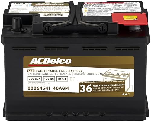
- High density negative paste, improves performance and...
- Enhanced life alloy or Silver Calcium stamped alloy...
- Calcium lead positive grid, maximizes conductivity and...
- Robust envelope separator with puncture resistant back...
- Vent cap design that resists acid leakage

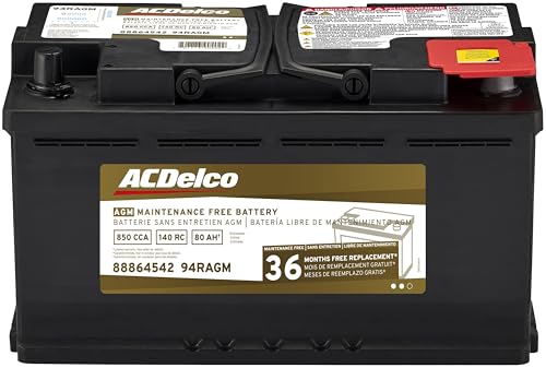
- High density negative paste, improves performance and...
- Enhanced life alloy or Silver Calcium stamped alloy...
- Calcium Lead positive grid, maximizes conductivity and...
- Robust Envelope Separator with puncture-resistant back...
- Vent cap design that resists acid leakage
If the PDF is very large, it may not load in the preview below.
Some older TSBs had multiple PDFs — visit the NHTSA Website to view all PDFs.
If the TSB PDF does not show, download or view it on the NHTSA Website.
Click on the (+) Plus Sign
Then Click on Associated Document(s)
Search NHTSA Database for Recalls
Search NHTSA Database for Vehicle Investigations
View Latest Vehicle Investigations
Search NHTSA Database for Vehicle Complaints
View Latest Vehicle Complaints
TSB/Document ID: IK1900198
Replacement Service Bulletin Number:
MFR Communication Date: 2014-06-04
MFR Internal Campaign ID/Software Version:
Communication Type: Service Bulletin/Repair Instructions
NHTSA Components: ELECTRICAL SYSTEM:12V/24V/48V BATTERY
MFR Component System:
MFR Component Subsystem:
Previous TSB | Next TSB |

- [Notice] When you receive a used device, it may be a customer return resold by Amazon without inspection. You can exchange it for a new one through Amazon. As this situation is unavoidable, we sincerely apologize. For any issues, contacting us via Amazon's "Messages" is the best way. THINKSCAN 689BT Bidirectional Scan Tool Can Be Used Immediately After It is Turned On, Without Complicated Registration Process, Which is More Convenient & Quick.
- Full Bi-Directional Control & 3000+ Active Tests: Take control and test components like actuators, fuel injectors, relays, and cooling fans in real time. You’ll quickly see if the problem is in the part itself or the control module — saving you hours of guesswork and frustrating trial-and-error.
- Advanced ECU Coding Capabilities: Handle module matching and hidden feature activation with confidence. When you replace an ECU or want to customize settings, this obd2 scanner diagnostic bi directional tool gives you the professional-level capabilities you need without the dealership price tag.
- 34+ Useful Reset and Maintenance Functions: Complete everyday service tasks smoothly with a wide range of helpful reset and maintenance functions. Whether you’re keeping up with regular upkeep or tackling a specific job, this scanner makes maintenance simpler and less stressful for both DIYers and pros.
- Comprehensive Full System Diagnostics: Diagnose every major system — Engine, Transmission
 , ABS, SRS, TPMS, and more — all in one place. Finally stop wondering if you’re missing something important; get the full picture and clear codes with ease.

- Top Reasons to Choose the D7S OBD2 Scanner: XTOOL D7S car scan tool, an upgrade of XTOOL D7, offers comprehensive features for automotive technicians, workshops, and DIY enthusiasts 1. Upgraded Hardware: 2+64GB memory, rear camera, intuitive interface, foldable bracket 2. Complete Diagnostics: FCA Autoauth, OE-level all system scan, 39+ maintenance services, 4K+ bidirectional, CANFD/DoIP protocol 3. Advanced Capabilities: ECU coding, PMI functions 4. Wide Compatibility: Support 10,000+ models, covering 99% vehicle brands 5. Multi-language: Available in 22+ languages, No IP Restrictions 6. 3-Year Updates: Save 300 bucks on software updates for the latest features and optimizations
- 2026 Upgraded D7S Car Scanner Features: The newly 2026 D7S V2.0 scanner for car brings exciting features for advanced vehicle diagnostics and enhanced user experience 1. FCA AutoAuth: Now supports FCA SGW module for Chrysler, for Jeep, for Dodge (2018+), for Fiat (2017+), enabling faster vehicle communication without gateway restrictions 2. PMI (Offline ECU Programming): Allows for Ford, for Lincoln, and for Mazda ECU programming for new modules 3. Optimized Diagnostic Report 2.0: Personalized reports with logos and customer info for auto shops. Note: Compatibility varies by cars, please check before order
- Cost-effective ECU Coding Scan Tool for Specific Brands: Enhance your vehicle's performance with XTOOL D7S! This obd2 scanner all systems bidirectional offers advanced capabilities at an affordable price, supports online for BMW, for Benz and offline for BENZ, for MIT, along with PMI functions for Ford, for Mazda, and for Lincoln. Ideal for technicians and DIY enthusiasts, this automotive scanner diagnostic tool optimizes vehicle performance and enhances the driving experience. Note: Not for all cars and modules, please send car VIN to check the compatibility before purchase
- OE All System Diagnostic & 8 Pids Graphing: XTOOL D7S is a comprehensive all system bi directional obd2 scanner that delivers dealer-level diagnostics, completely controlling over your vehicle’s performance and health. This automotive scan tool can read and clear DTCs, view live data and ECU information, retrieve freeze frames, and perform active tests and full obd2 functions. This bi-directional scan tool can can identify your vehicle's make, model, and year information with just one click and show up to 8 PIDs live data with options for CSV viewing, playback, and recording for in-depth analysis. It is easy-to-use for both professionals and beginners, helping pinpoint issues efficiently
- 3 Years Software Update, Value for Money: With 3 years of software updates and 22+ languages(no IP restrictions), XTOOL D7S auto scanner code scanner ensures ongoing compatibility for the latest car models and improved diagnostic functions. This all system vehicle diagnostic scanner comes with a 30-day return policy and a 24-month repair for dependable performance. XTOOL are dedicated to your satisfaction, so enjoy seamless support and lifetime expert assistance. Should you encounter any issues or concerns, don’t hesitate to reach out XTOOL. D7S with newest update with 22 languages freely transfer without authorization, check details from setting-language or from XTOOL

- 【✅Compared to BOSSCOMM IF742, IF745 Offers Full-System Diagnostics】The BOSSCOMM IF745 car diagnostic scanner is an upgraded model of IF742. In addition to supporting all OBD2 Code Reader functions and 6 reset options (ABS/EPB/SAS/BMS/Oil/Throttle), it expands diagnostics from 4 systems (Check Engine/ABS/SRS/Transmission) to vehicle All systems, including Steering, Suspension, and Body Electronics. This provides deeper, more comprehensive diagnostic capabilities.
- 【✨6 Essential Resets: ABS Bleeding, Oil, EPB, SAS, Throttle, BMS】The BOSSCOMM IF745 obd2 scanner diagnostic tool swiftly purges air from brake lines to restore braking sensitivity, fine-tunes maintenance cycles to eliminate false alerts, resolves parking brake issues with one-click control, recalibrates steering sensors for stability, optimizes engine idling/acceleration for smoother performance, and deeply resets battery systems to extend lifespan and range via precise parameter adjustments.❗NOTE: Does NOT support bidirectional control, coding, or programming.
- 【✨Deep Diagnostics for All Vehicle System Modules】Beyond code reading/clearing and ECU information retrieval, our all-in-one data stream feature lets you inspect all current fault codes and their locations across the vehicle’s systems. This vehicle code reader helps you turn off dashboard warning lights and perform a comprehensive self-check of your car at home—no more back-and-forth trips to the repair shop or hefty inspection fees.
- 【✨10 OBD2 Functions】The BOSSCOMM IF745 scan tool’s DTC Lookup instantly translates fault codes into user-friendly explanations, its I/M Readiness feature streamlines emissions testing with a single tap, and Freeze Frame lets you pinpoint the exact moment of a fault for in-depth root-cause diagnosis. Combined with a live data dashboard and advanced diagnostics (O2S, OBMon, EVAP), it delivers comprehensive insights for confident troubleshooting.
- 【✨10,000+ Car Models, AutoVIN, 13 Languages】The BOSSCOMM IF745 vehicle scanner diagnostic tool covers 73+ global car brands and offers support in 13 languages, making it perfect for DIYers, auto mechanics, or as a thoughtful gift. With a single-click AutoVIN feature, it instantly retrieves vehicle serial numbers, streamlining diagnostics for users globally. This adaptable tool balances user-friendliness with precision, catering to both personal and professional requirements.✅Unsure about compatibility? Compatibility will vary on vehicles' model and year, pls reach us via 📧 [email protected] 📧 before purchase.
This product presentation was made with AAWP plugin.