
NHTSA ID Number: 10115856
Manufacturer Communication Number: SD03905US006
TSB/Document Date: 2017-08-25
Summary
Update to Bendix Service Data sheet used to describe the operation and troubleshooting procedure for the Bendix QRN quick release valve.
SD-03-905
®
Bendix® QRN™ Quick Release Valve
MOUNTING HOLE (2)
SUPPLY PORT
UPPER BODY
DIAPHRAGM
DELIVERY
PORT
DELIVERY
PORT
LOWER
BODY
SPRING FOLLOWER
INSERT A
EXHAUST PORT
LOCKWASHER
SEALING RING
CAP SCREW
DIFFERENTIAL SPRING
Figure 1 – Bendix® QRN™ Quick Release Valve
DESCRIPTION
The function of the Bendix® QRN™ quick release valve is to
“speed up” the exhaust of air from the actuators it serves. It
is generally mounted on the vehicle axle midway between
the two actuators connected to it.
Various pipe thread sizes are available for the single supply
port and two delivery ports of the QRN valve. Mounting
the valve is accomplished via two 11/32" diameter holes
on 1-1/2" centers.
In the standard (Refer to Figure 1) QRN valve, a flat circular
diaphragm is installed between the nonmetallic upper body
and stamped steel lower body. An o-ring seals the two body
halves which are held together using four 1/4" machine
screws and flange nuts.
OPERATION
In its standard configuration, the QRN valve is supplied with
a 1 psi (6.9 kPa) maximum differential. For example, with
supply pressure at 10 psi (68.9 kPa) delivery pressure is 9
psi (61.8 kPa). Higher differential pressures are available
for special applications and are obtained by the addition
of a spring and diaphragm follower to the standard QRN
valve. Refer to Figure 1 - Insert A.
With no air pressure applied to the QRN valve, the
diaphragm is slightly flexed by the upper and lower body.
In this condition the center portion of the diaphragm rests on
the exhaust port in the lower body while the outer edge and
opposite side of the diaphragm rests against the sealing
lip of the upper body. Refer to Figure 1.
1
GENERAL SAFETY GUIDELINES
WARNING! PLEASE READ AND
FOLLOW THESE INSTRUCTIONS
TO AVOID PERSONAL INJURY OR DEATH:
When working on or around a vehicle, the following
guidelines should be observed AT ALL TIMES:
▲Park the vehicle on a level surface, apply the parking
brakes and always block the wheels. Always wear personal
protection equipment.
▲Stop the engine and remove the ignition key when working
under or around the vehicle. When working in the engine
compartment, the engine should be shut off and the ignition
key should be removed. Where circumstances require that
the engine be in operation, EXTREME CAUTION should be
used to prevent personal injury resulting from contact with
moving, rotating, leaking, heated or electrically-charged
components.
▲Do not attempt to install, remove, disassemble or
assemble a component until you have read, and thoroughly
understand, the recommended procedures. Use only the
proper tools and observe all precautions pertaining to use
of those tools.
▲If the work is being performed on the vehicle’s air brake
system, or any auxiliary pressurized air systems, make
certain to drain the air pressure from all reservoirs before
beginning ANY work on the vehicle. If the vehicle is
equipped with a Bendix® AD-IS® air dryer system, a Bendix®
DRM™ dryer reservoir module, or a Bendix ® AD-9si ® air
dryer, be sure to drain the purge reservoir.
▲Following the vehicle manufacturer’s recommended
procedures, deactivate the electrical system in a manner
that safely removes all electrical power from the vehicle.
▲Never exceed manufacturer’s recommended pressures.
▲Never connect or disconnect a hose or line containing
pressure; it may whip and/or cause hazardous airborne
dust and dirt particles. Wear eye protection. Slowly open
connections with care, and verify that no pressure is
present. Never remove a component or plug unless you are
certain all system pressure has been depleted.
▲Use only genuine Bendix ® brand replacement parts,
components and kits. Replacement hardware, tubing, hose,
fittings, wiring, etc. must be of equivalent size, type and
strength as original equipment and be designed specifically
for such applications and systems.
▲Components with stripped threads or damaged parts should
be replaced rather than repaired. Do not attempt repairs
requiring machining or welding unless specifically stated
and approved by the vehicle and component manufacturer.
▲Prior to returning the vehicle to service, make certain all
components and systems are restored to their proper
operating condition.
▲For vehicles with Automatic Traction Control (ATC), the ATC
function must be disabled (ATC indicator lamp should be
ON) prior to performing any vehicle maintenance where
one or more wheels on a drive axle are lifted off the ground
and moving.
▲The power MUST be temporarily disconnected from the
radar sensor whenever any tests USING A DYNAMOMETER
are conducted on a vehicle equipped with a Bendix ®
Wingman ® system.
▲You should consult the vehicle manufacturer's operating
and service manuals, and any related literature, in
conjunction with the Guidelines above.
2
APPLY
Air entering the supply port of the Bendix® QRN™ quick
release valve causes the center portion of the diaphragm
to seal the exhaust port. Simultaneously, the outer edge
of the diaphragm moves away from the sealing lip of the
upper body allowing air to flow from the supply port out
the delivery ports.
BALANCE
When air pressure on both sides of the diaphragm
is approximately equal (1 psi differential), the natural
resiliency of the diaphragm material causes the outer
edge of the diaphragm to move into contact with the upper
body sealing lip. The QRN valve exhaust remains sealed
because air pressure bears against the center portion of
the diaphragm from one side only.
RELEASE
When air pressure is reduced or removed from the QRN
quick release valve supply port, the air pressure on the
delivery side of the diaphragm is greater than that on the
supply side. The higher delivery side pressure holds the
outer edge of the diaphragm against the upper body sealing
lip while simultaneously moving the center portion away
from the exhaust port. Air from the delivery ports flows out
the exhaust. When air pressure on the delivery side of the
diaphragm equals the pressure on the supply side, the
center portion of the diaphragm moves into contact with
the exhaust port.
PREVENTIVE MAINTENANCE
IMPORTANT
Review the Bendix Warranty Policy before performing any
intrusive maintenance procedures. A warranty may be
voided if intrusive maintenance is performed during the
warranty period.
No two vehicles operate under identical conditions, as
a result, maintenance intervals may vary. Experience is
a valuable guide in determining the best maintenance
interval for air brake system components. At a
minimum, the QRN valve should be inspected every
12 months or 3600 operating hours, whichever comes
first, for proper operation. Should the QRN valve not
meet the elements of the operational tests noted in
this document, further investigation and service of the
valve may be required.
OPERATING AND LEAKAGE TESTS
1. Apply 100 psi (689 kPa) air pressure to the supply port
of the Bendix® QRN™ quick release valve and note that
the device connected to the valve responds promptly.
2. With 100 psi (689 kPa) air pressure applied to the
QRN valve SUPPLY port, apply a soap solution to the
exhaust port and around the junction of the upper and
lower body halves.
A. No leakage is permitted between the body halves.
B. Leakage of greater than a 1 inch (25.4 mm) bubble
in three seconds at the exhaust port is unacceptable.
3. Release the air pressure at the supply port and note
that the device connected to the QRN valve responds
promptly and returns to a zero air pressure condition.
4. If the QRN valve does not function as described or
if leakage is excessive, it is recommended that it be
replaced with a new or remanufactured unit or repaired
using a genuine Bendix® maintenance kit.
5. Use only genuine Bendix replacement parts and
components.
A. Only components, devices, mounting and attaching
hardware specifically designed should be used.
B. Replacement hardware, tubing, hose, fittings, etc.
should be of equivalent size, type, length, and
strength as the original equipment.
C. Make certain that when replacing tubing or hose, all
supports, clamps or suspending devices that were
originally installed by the vehicle manufacturer are
reinstalled.
6. Devices with stripped threads or damaged parts should
be replaced. Repairs requiring machining should not
be attempted.
REMOVING THE BENDIX® QRN™ VALVE
1. Park the vehicle on a level surface. Block the wheels
and/or hold the vehicle by means other than the air
brakes.
2. Drain all air brake system reservoirs.
3. Identify, mark and disconnect all air lines from the valve.
4. Remove all tubing or hose fittings from the valve.
5. Remove the valve mounting hardware and the valve.
DISASSEMBLY
The following disassembly procedure is provided as a
reference. Before disassembling the QRN valve, a Bendix
maintenance kit or genuine replacement parts should be
available.
1. Remove the four 1/4" flange nuts and bolts that secure
the upper and lower body halves. NOTE: Before
removing the last two nuts and bolts completely, check
the opening between the body halves to determine if
the QRN valve has a differential spring installed. If so,
a light spring load should be anticipated and can be
easily controlled by manually holding the body halves
together.
2. Separate the body halves and remove the diaphragm
(and diaphragm follower and spring if so equipped).
3. Remove the sealing ring between the body halves.
CLEANING & INSPECTION
1. Clean the upper and lower body halves; also the
diaphragm follower and spring (if applicable) in mineral
spirits. Do not immerse nonmetallic components for a
prolonged period of time (no more than 10 minutes).
Dry all parts thoroughly.
2. It is recommended that the diaphragm and sealing ring
be replaced after disassembly.
3. Inspect the upper body for galled threads and cracks.
If found, the entire QRN valve should be replaced.
4. Inspect the interior valve portion of the lower body for
heavy corrosion and pitting. If found, replace the entire
QRN valve assembly.
5. If applicable, inspect the diaphragm follower and spring
for any corrosion and pitting, replace if necessary.
ASSEMBLY
1. Place the supply port of the upper body down on a clean,
level work surface. Install the flat circular diaphragm in
the upper body making certain it is CENTERED.
2. If applicable, install and center the diaphragm follower
with its flat flange side against the diaphragm. Install
the spring on the diaphragm follower.
3. Install the sealing ring on the lower body and carefully
install the lower body on the upper body. Make certain
that the diaphragm remains centered in the upper body
and the sealing ring enters its groove in the upper body.
4. Install the four 1/4" flange nuts and bolts and torque to
60 in-lbs (6.78 Nm).
3
INSTALLING THE BENDIX® QRN™ VALVE
1. Mount the Bendix® QRN™ quick release valve on the
vehicle with the exhaust port pointing down.
2. Install the tubing or hose fittings in the upper body of
the valve. If a thread sealant is used, make certain that
this material will not enter the valve during use.
IMPORTANT
WHEN INSTALLING FITTINGS, DO NOT TORQUE
BEYOND THE FOLLOWING OR DAMAGE TO THE
UPPER BODY MAY RESULT:
12 ft-lbs. (16.3 Nm) for the supply port
10 ft-lbs. (13.6 Nm) for the delivery ports
(or 2-1/2 turns beyond finger tight for each.)
3. Connect the air lines to the valve as identified in Step
4 of "Removing the Bendix® QRN™ Valve".
4. Perform the “Operating and Leakage Tests” before
placing the vehicle in service.
Log-on and Learn from the Best
On-line training that's available when you are
Visit www.brake-school.com.
4
24/7/365.
SD-03-905 Rev. 006 © 2017 Bendix Commercial Vehicle Systems LLC, a member of the Knorr-Bremse Group 01/17 • All rights reserved.
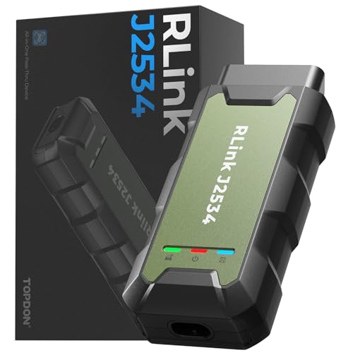
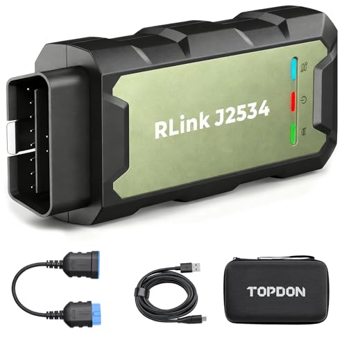
- Advanced VCI Box, Industry-leading J2534 Pass-Thru...
- High-Speed OEM-Level Diagnostics & Programming: Unlock true...
- Coverage for 17 Car Brands & Ultra Reliability: Works...
- User-Friendly RLink Platform & Expert Support: TOPDON’s...
- 6.6 ft USB-C Cable & Portable Storage Case: The RLink J...
If the PDF is very large, it may not load in the preview below.
Some older TSBs had multiple PDFs — visit the NHTSA Website to view all PDFs.
If the TSB PDF does not show, download or view it on the NHTSA Website.
Click on the (+) Plus Sign
Then Click on Associated Document(s)
Search NHTSA Database for Recalls
Search NHTSA Database for Vehicle Investigations
View Latest Vehicle Investigations
Search NHTSA Database for Vehicle Complaints
View Latest Vehicle Complaints
TSB/Document ID: SD03905US006
Replacement Service Bulletin Number:
MFR Communication Date: 2017-01-31
MFR Internal Campaign ID/Software Version:
Communication Type: Service Bulletin/Repair Instructions
NHTSA Components: EQUIPMENT:OTHER:OWNERS/SERVICE/OTHER MANUAL
MFR Component System:
MFR Component Subsystem:
Previous TSB | Next TSB |

- [Notice] When you receive a used device, it may be a customer return resold by Amazon without inspection. You can exchange it for a new one through Amazon. As this situation is unavoidable, we sincerely apologize. For any issues, contacting us via Amazon's "Messages" is the best way. THINKSCAN 689BT Bidirectional Scan Tool Can Be Used Immediately After It is Turned On, Without Complicated Registration Process, Which is More Convenient & Quick.
- Full Bi-Directional Control & 3000+ Active Tests: Take control and test components like actuators, fuel injectors, relays, and cooling fans in real time. You’ll quickly see if the problem is in the part itself or the control module — saving you hours of guesswork and frustrating trial-and-error.
- Advanced ECU Coding Capabilities: Handle module matching and hidden feature activation with confidence. When you replace an ECU or want to customize settings, this obd2 scanner diagnostic bi directional tool gives you the professional-level capabilities you need without the dealership price tag.
- 34+ Useful Reset and Maintenance Functions: Complete everyday service tasks smoothly with a wide range of helpful reset and maintenance functions. Whether you’re keeping up with regular upkeep or tackling a specific job, this scanner makes maintenance simpler and less stressful for both DIYers and pros.
- Comprehensive Full System Diagnostics: Diagnose every major system — Engine, Transmission, ABS, SRS, TPMS, and more — all in one place. Finally stop wondering if you’re missing something important; get the full picture and clear codes with ease.

- Top Reasons to Choose the D7S OBD2 Scanner: XTOOL D7S car scan tool, an upgrade of XTOOL D7, offers comprehensive features for automotive technicians, workshops, and DIY enthusiasts 1. Upgraded Hardware: 2+64GB memory, rear camera, intuitive interface, foldable bracket 2. Complete Diagnostics: FCA
 Autoauth, OE-level all system scan, 39+ maintenance services, 4K+ bidirectional, CANFD/DoIP protocol 3. Advanced Capabilities: ECU c0ding, PMI functions 4. Wide Compatibility: Support 10,000+ models, covering 99% vehicle brands 5. Multi-language: Available in 22+ languages, No IP Restrictions 6. 3-Year Updates: Save 300 bucks on software updates for the latest features and optimizations
 - 2026 Upgraded D7S Car Scanner Features: The newly 2026 D7S V2.0 scanner for car brings exciting features for advanced vehicle diagnostics and enhanced user experience 1. FCA AutoAuth: Now supports FCA SGW module for Chrysler, for Jeep, for Dodge (2018+), for Fiat (2017+), enabling faster vehicle communication without gateway restrictions 2. PMI (Offline ECU Pr0gramming): Allows for Ford, for Lincoln, and for Mazda ECU pr0gramming for new modules 3. Optimized Diagnostic Report 2.0: Personalized reports with logos and customer info for auto shops. Note: Compatibility varies by cars, please check before order
- 39+ Services/Resets/Adaptations/Relearns/Calibrations: XTOOL D7S full system car scanner diagnostic tool tackles 99% of common car issues through its 36+ special functions, including Oil Reset, EPB, SAS, BMS, Throttle Reset, Injector C0ding, ABS Bleed, TPMS Reset, Power Balance, etc and also covers specific-vehicle functions like Crank Sensor Relearn, ABS Initialization, Cylinder Power Balance, Fuel Trim Reset, Idle Relearn etc. This car diagnostic scanner enhances efficiency, making repairs and maintenance hassle-free. Tip: DO NOT for All vehicles, please check compatibility first
- Cost-effective ECU C0ding Scan Tool for Specific Brands: Enhance your vehicle's performance with XTOOL D7S! This obd2 scanner all systems bidirectional offers advanced capabilities at an affordable price, supports online for BMW, for Benz and offline for BENZ, for MIT, along with PMI functions for Ford, for Mazda, and for Lincoln. Ideal for technicians and DIY enthusiasts, this automotive scanner diagnostic tool optimizes vehicle performance and enhances the driving experience. Note: Not for all cars and modules, please send car VIN to check the compatibility before purchase
- OE All System Diagnostic & 8 Pids Graphing: XTOOL D7S is a comprehensive all system bi directional obd2 scanner that delivers dealer-level diagnostics, completely controlling over your vehicle’s performance and health. This automotive scan tool can read and clear DTCs, view live data and ECU information, retrieve freeze frames, and perform active tests and full obd2 functions. This bi-directional scan tool can can identify your vehicle's make, model, and year information with just one click and show up to 8 PIDs live data with options for CSV viewing, playback, and recording for in-depth analysis. It is easy-to-use for both professionals and beginners, helping pinpoint issues efficiently

- 【✅Compared to BOSSCOMM IF742, IF745 Offers Full-System Diagnostics】The BOSSCOMM IF745 car diagnostic scanner is an upgraded model of IF742. In addition to supporting all OBD2 Code Reader functions and 6 reset options (ABS/EPB/SAS/BMS/Oil/Throttle), it expands diagnostics from 4 systems (Check Engine/ABS/SRS/Transmission) to vehicle All systems, including Steering, Suspension, and Body Electronics. This provides deeper, more comprehensive diagnostic capabilities.
- 【✨10 OBD2 Functions】The BOSSCOMM IF745 scan tool’s DTC Lookup instantly translates fault codes into user-friendly explanations, its I/M Readiness feature streamlines emissions testing with a single tap, and Freeze Frame lets you pinpoint the exact moment of a fault for in-depth root-cause diagnosis. Combined with a live data dashboard and advanced diagnostics (O2S, OBMon, EVAP), it delivers comprehensive insights for confident troubleshooting.
- 【✨Deep Diagnostics for All Vehicle System Modules】Beyond code reading/clearing and ECU information retrieval, our all-in-one data stream feature lets you inspect all current fault codes and their locations across the vehicle’s systems. This vehicle code reader helps you turn off dashboard warning lights and perform a comprehensive self-check of your car at home—no more back-and-forth trips to the repair shop or hefty inspection fees.
- 【✨6 Essential Resets: ABS Bleeding, Oil, EPB, SAS, Throttle, BMS】The BOSSCOMM IF745 obd2 scanner diagnostic tool swiftly purges air from brake lines to restore braking sensitivity, fine-tunes maintenance cycles to eliminate false alerts, resolves parking brake issues with one-click control, recalibrates steering sensors for stability, optimizes engine idling/acceleration for smoother performance, and deeply resets battery systems to extend lifespan and range via precise parameter adjustments.❗NOTE: Does NOT support bidirectional control, coding, or programming.
- 【✨10,000+ Car Models, AutoVIN, 13 Languages】The BOSSCOMM IF745 vehicle scanner diagnostic tool covers 73+ global car brands and offers support in 13 languages, making it perfect for DIYers, auto mechanics, or as a thoughtful gift. With a single-click AutoVIN feature, it instantly retrieves vehicle serial numbers, streamlining diagnostics for users globally. This adaptable tool balances user-friendliness with precision, catering to both personal and professional requirements.✅Unsure about compatibility? Compatibility will vary on vehicles' model and year, pls reach us via 📧 [email protected] 📧 before purchase.

This product presentation was made with AAWP plugin.