
| “This site contains affiliate links for which OEMDTC may be compensated” |
NHTSA ID Number: 10165671
Manufacturer Communication Number: 059-260-00
Summary
Hydraulic Drum Brake Replacement Shoe Lining Kit – 10″ x 2-1/4″ or 12″ x 2″ Installation Instructions
1 Affected Product
Equipment
| BRAND | PART NO. | PRODUCTION DATES |
| DEXTER AXLE CO | DEXTER AXLE CO | |
INSTALLATION INSTRUCTIONS
Hydraulic Drum Brake Replacement Shoe Lining Kit – 10” x 2¼” or 12” x 2”
IT IS RECOMMENDED THAT ALL FOUR (4) SHOE/LININGS BE REPLACED AT THE SAME TIME TO ENSURE BALANCED BRAKING PERFORMANCE. The brakes and shoes shown above are free backing with pivoting primary brake shoes. If your kit is for standard style brakes, both shoes will look similar with the primary shoes having the shortest length brake linings. Primary shoes should be installed to face the front of the trailer, while the secondary shoes face the rear of the trailer.
| CAUTION |
|
Removing the Old Brake Shoe/Linings
- Elevate and support the trailer unit per trailer manufacturer instructions. Remove wheel.
- If the brake drum does not rotate freely it may be difficult to remove. This may require under adjusting the brakes to free the brake shoes from the drum. This can be accomplished by rotating the star adjuster located through the bottom rear of the brake assembly.
- Remove the hub dust cap by carefully prying it progressively off or gently tapping it to the side as the brake drum is rotated by hand. Remove excess grease to expose the spindle nut and its retainer or cotter pin. Depending on how the trailer is equipped, carefully remove any reusable nut retainers or remove the cotter pin. Loosen and remove the spindle nut. This can be done by hand or may require a wrench. Be careful not to damage spindle threads on removal.
- Hold the outer (front) tapered roller bearing and thrust washer in place by hand while removing the drum to prevent them falling out during the disassembly. Turn the drum over and remove the inner bearing seal with a seal puller or appropriate pry bar. Do not attempt to drive the seal out by striking the seal or inner bearing. Inspect bearings for any imperfections on the rollers, cone, or race. If replacement is needed, it must be done in pairs. If not replacing bearings, return them to their original location.
- Inspect the drum and resurface/replace if necessary. The maximum machining diameter is typically stamped into the drum. Inspect for seal leaks and replace components if necessary before replacing your brake shoes.
| CAUTION |
|
- Screw the brake star adjuster in all the way to make it easier to remove the brake springs.
- Note the correct position of the star adjuster and the brake spring prior to removal. Each will need to be reassembled in the same manner to assure proper brake function.
- Remove the two retractor springs and the flat washer plate using the appropriate retractor spring removal tool. Please note the primary shoe (front) return spring is on top.
- Using a hold down spring removal tool, remove the secondary (rear) shoe-retaining washer, retaining spring and keeper pin. Hold outward pressure on the keeper pin with one hand while pressing inward on the shoe retaining washer with the tool. Turn it a quarter turn to release the keeper pin head. Remove the hold down spring and washer. Lift the top of the secondary shoe off the anchor pin and pull it out slightly. Pivot it forward to release the tension on the (bottom) spanner spring so that the star adjuster and spring can be removed and set aside. Remove the hold down pin through the rear of the backing plate.
- Remove the primary shoe retaining spring, keeper pin and washers by the same method and carefully pivot the shoe away from the wheel cylinder push rod. On free backing brakes, remove the bolt, lock nut, and retaining loop from the top of the primary shoe and the pivoting pin, spring, bolt, and nut from the bottom of the shoe. Retain them for later re-installation on the replacement shoes.
- Unscrew the brake adjuster and clean the threads with a wire brush. Lubricate the adjuster threads lightly with a high temperature anti-seize grease and screw the adjuster all the way in (minimum length) for later re-installation.
- Inspect hydraulic wheel cylinder for fluid leaks. Replace wheel cylinder assembly if leakage is detected.
Installing the New Brake Shoes/Lining
If you have free backing brakes, reinstall the hardware from the original primary shoe as required onto the replacement primary shoe. Avoid torquing lock nut and bolt together as there should be a gap between components. The gap allows components to swivel or slide during operation.
- Assemble the primary shoe (with the shorter lining) first on the front facing side of the backing plate. On free backing brake shoes, put the round loop at the top of the shoe over the backing plate anchor post before installing the keeper pin and its hold down spring. If the shoes in this kit have reinforcement plates on the shoe webs, install the shoes with the reinforcement plates towards the backing plate. Secure the hold down spring on the end of the hold down pin by holding the pin pressed outward with one hand and installing the hold down washer by rotating the tool a quarter turn to secure it.
- Assemble the secondary shoe in the same manner. The secondary shoe is the shoe with the longest lining, and mounts on the side of the backing plate closest to the rear of the trailer.
- Spread the brake shoes slightly apart at the bottom and insert the star adjuster into the notches at the bottom of the brake shoes in the direction it was originally installed. Install the spanner spring in the holes at the bottom of the primary shoe. Ensure the adjuster is correctly seated upon reassembly.
- Place the flat washer over the backing plate anchor pin and install the secondary return spring with the installation tool.
- Install the primary return spring with the installation tool.
- Inspect the assembly for all components being properly in place. The primary and secondary shoes should be firmly seated against their anchor pins/springs, with the ends of the pins securely seated at 90 degrees across the slots in the spring keeper washers. The retaining and spanner springs should be fully hooked and seated in their respective holes in the brake shoes. The star adjuster ends firmly seated in their notches in the brake shoes, etc. If the completed assembly is not centered on the mounting plate, bump the shoes from both directions with your hands to center them and assure everything is seated at the minimum assembled diameter.
- Remove the rubber dust plug from the rear access hole in the backing plate. Insert a brake adjusting spoon or flat screw driver in the access hole and TAKE NOTE which direction the star adjuster needs to be rotated in order to expand the brake shoes.
- Clean, inspect, and/or replace the bearing cones and races, and install a new inner wheel bearing seal per the Light Duty Service Manual. Wipe a thin coat of the lubricant on the rubber lip of the seal. Grease the bearing journals on the spindle to help with drum installation. Avoid getting any grease on the brake linings.
- Center the hub-drum on the spindle and slide it over the brake shoes. Do not nick the wheel bearing seal on installation. Slide the drum over the shoes with a slight rotation in the direction of forward travel to help align and fully seat the inner bearing and seal on the spindle. Install the outer bearing, thrust washer, nut locking tab washer (if applicable) and spindle nut finger tight.
- Adjust the bearings in the steps below:
For standard grease or oil axles using cotter pin:
-
- After placing the hub, bearings, washers, and spindle nut back on the axle spindle in reverse order as detailed in the previous section on hub removal, rotate the hub assembly slowly while tightening the spindle nut to approximately 50 Ft. Lbs. (12” wrench or pliers with full hand force.)
- Then loosen the spindle nut to remove the torque. Do not rotate the hub.
- Finger tighten the spindle nut until just snug.
- Back the spindle nut out slightly until the first castellation lines up with the cotter key hole and insert the cotter pin.
- Bend over the cotter pin legs to secure the nut.
- Nut should move freely with only restraint being the cotter pin.
For E-Z Lube® axles using the new nut retainer:
-
- After placing the hub, bearings, washers, and spindle nut back on the axle spindle in reverse order as detailed in the previous section on hub removal, rotate the hub assembly slowly while tightening the spindle nut to approximately 50 Ft. Lbs. (12” wrench or pliers with full hand force.)
- Then loosen the spindle nut to remove the torque. Do not rotate the hub.
- Finger tighten the nut until just snug, align the retainer to the machined flat on the spindle and press the retainer onto the nut. The retainer should snap into place. Once in place, the retainer/nut assembly should be free to move slightly.
- If the nut is too tight, remove the retainer and back the nut off approximately one twelfth of a turn and reinstall the retainer. The nut should now be free to move slightly.
- Reinstall grease cap.
- Install a new cotter pin, nut retainer, or bend tabs on the locking tab washer to the original specifications. If moving the spindle nut is required to install a cotter pin or locking washer only do so in a loosing direction. A properly installed nut and retainer should make contact with the thrust washer but not apply any tension.
- Install the dust cap by driving it in with a method that applies pressure to the perimeter not the face.
Brake Adjustment
Dexter electric brakes that have a self adjusting feature require no manual adjustment. Brakes not equipped with this feature can be adjusted by using the following procedure:
Brakes should be adjusted (1) after the first 200 miles of operation when the brake shoes and drums have “seated,” (2) at 3,000 mile intervals, (3) or as use and performance requires. The brakes should be adjusted in the following manner:
- Jack up trailer and secure on adequate capacity jack stands. Follow trailer manufacturer’s recommendations for lifting and supporting the unit. Make sure the wheel and drum rotates freely.
| CAUTION |
| Do not lift or support the trailer on any part of the axle or suspension system. Never go under any trailer unless it is properly supported on jack stands which have been rated for the load. Improperly supported vehicles can fall unexpectedly and cause serious injury or death. |
- If equipped, remove the adjusting hole cover, if present, from the adjusting slot on the bottom of the brake backing plate.
- With a screwdriver or standard adjusting tool, rotate the star wheel of the adjuster assembly to expand the brake shoes. Adjust the brake shoes out until the pressure of the linings against the drum makes the wheel very difficult to turn. Note: For drop spindle axles, a modified adjusting tool may be necessary.
- Then rotate the star wheel in the opposite direction until the wheel turns freely with a slight lining drag.
- Replace the adjusting hole cover, if available, and lower the wheel to the ground.
- Repeat the above procedure on all brakes. For best results, the brakes should all be set at the same clearance.
Images in this instruction sheet are used for illustration purposes only and may not match your exact kit.
059-260-00 2019.10
059-260-00
https://www.nhtsa.gov/recalls?nhtsaId=10165671
https://static.nhtsa.gov/odi/tsbs/2019/MC-10165671-0001.pdf
 Loading...


- Self-Adjusting Electric Brake: Say goodbye to manual adjustments! Dive into the world of 12" x 2" electric trailer brake assemblies that self-adjust. It's not just smart; it's efficient and gives your trailer that smooth braking touch.
- Hassle-Free Installation: DIY's best friend! Our electric trailer brake is straightforward and a breeze to install. It's ready to install right out of the box and boasts high compatibility. Wherever you are, installation is just a few steps away.
- Built for the Long Haul: Keep on rolling! With a lifespan of up to 30,000 kilometers, these trailer brakes are in it for the long haul, designed for your trailer's daily adventures. Constructed from premium materials, our brakes promise robust durability and resistance to wear and tear.
- Versatility at Its Best: The trailer brake kit has a broad range of applications, including towing trailers, transporting goods, camping trips, and more. It's compatible with Dexter, AL-KO (a brand under the former), and other trailer axles.
- Top-Notch Packaging: When it comes to packaging, we don't just box; we care. Our trailer electric brake kit is packaged above industry standards. Every brake is meticulously checked and wrapped to ensure what you get is nothing short of perfect.
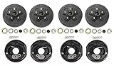
- 4 x trailer 5 on 4.5" hub drum kits + 4 x 10"x2-1/4" electric brakes for Dexter and other brands 3,500 lbs trailer axle
- Drum Bolt pattern: 5 on 4.5", bearing races and 1/2"-20 studs installed, Ref part #. 008-247-05, 84546
- Kits also includ: 4x L68149 inner cone bearings and 4x L44649 outer cone bearings, 4x Grease seals 1.719" x 2.565", 4x E Z lube grease caps with rubber plug; 20 cone wheel nuts 1/2"-20 thread
- Also include: 2 left + 2 right 10"x2-1/4" electric brakes with 3" center bore and 4" mounting bolts circle diamter
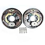
- Pair of 10" x 2.25" TruRdye electric trailer brake assemblies with parts.
- 4 Hole mounting, comes with mounting bolts, nuts, and lock washers
- For Alko, Dexter, Quality, or other popular trailer axle manufacturers.
- TruRyde Brakes
- TruRyde parts are manufactured to automotive standard in ISO/TS-16949 registered factory.

- 2x Trailer 6 on 5.5" B.C. hub drum Kits + 2x 12"x2" electric brakes for 5200-6000 Lbs Axle. Bolt pattern: 6 on 5.5";
- Kit also include: 2x 25580 inner cone bearings and 2x 15123 outer cone bearings, 2x Grease seals 2.25" x 3.371", 2x EZ lube grease caps with rubber plug, 12 cone wheel nuts 1/2"x20 thread,
- Also include: One right and one left 12" x 2" electric brakes with 3-1/4" center hole
- Ref drum part #. 008-201, 42656; ref brake part #. K23-180-00, K23-181-00

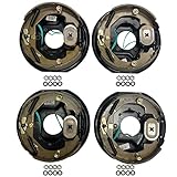
- 2-Pack 3,500 lbs. Trailer Axle Self Adjusting Electric Brake Kit 5-4.5" Bolt Circle
- 4 x 10" x 2 1/4" 5-4.5" bolt circle TruRyde hub and drums with parts (2 5/8" from center of one stud to the center of the next stud)
- 2 x 10" x 2 1/4" TruRyde Self-Adjusting electric backing plates
- Works with Al-Ko, Dexter, Lippert, and Quality Trailer Axles. TruRyde parts are manufactured to automotive standard in ISO/TS-16949 registered factory.
- Comes with TruRyde bearings, seals, lug nuts, open and closed grease caps, cotter pins, spindle washers, tang washers, spindle nuts, and brake mounting washers and nuts

- Compatible with: Fit For Alko/ for Dexter/ for Quality, and other brands 3,500lbs trailer axle
- Kit Includes: 2x 10" x 2-1/4" left electric brake assemblies, 2x 10" x 2-1/4" right electric brake assemblies, 16x spring pad, 16x nut
- Production and Installation: Strictly follow automotive standards and comply with the G3000 standard in the US; Easy to install
- Product Introduction: The AEagle electronic brake features non-asbestos brake linings for superior friction performance, ensuring longevity and enhanced braking capabilities.
- Quality Assurance: 12-month warranty! Tested before shipping.

- Set of two 12" x 2" electric trailer brake assembly, for most 5200lbs 6000lbs 7000lbs trailer axle;Center hole diameter: 3-1/4"
- Fits the wheel bolt pattern 6 lug or 8 lug,fits spline size #42 steel brake drum.Bolt hole spacing: 2.0" O.C. around the top,Bolt hole spacing: 3.0" O.C.across the bottom
- Replace :K23-180-00,K23-181-00;77-12EA-1-2;replace Axletech B12E-22 (12x2);Al-Ko Lippert,etc
- The trailer brakes are NOT self adjusting, unlike most drum brakes on cars and trucks,need to be done when installed and periodically thereafter.If you cannot adjust yourself, please find a professional adjustment
- JADODE electric and hydraulic trailer brake parts offers 3 years warranty.Note make sure it matches you size,hub has to fit over

- 10" x 2.25"electric trailer brake assembly (left & right side), fit most 3500lbs - 4000lbs trailer axle; 4-hole mount w/mounting bolt
- Fits the wheel bolt pattern 4 lug,fits spline size #84 steel drum; center hole diameter: 3" ; bolt circle diameter: 4"
- Replace 023-026-00 and 023-027-00;77-10-2;23-105, 23-106,296649;replace Dexter Lippert Al-Ko,etc brake assemblies
- The electric brakes are NOT self adjusting, unlike most drum brakes on cars and trucks,need to be done when installed and periodically thereafter.If you cannot adjust yourself, please find a professional adjustment
- JADODE electric and hydraulic trailer brake parts offers 3 years warranty.Note make sure it matches you size,hub has to fit over
Last update on 2024-04-12 / Affiliate links / Images from Amazon Product Advertising API
This product presentation was made with AAWP plugin.