
| “This site contains affiliate links for which OEMDTC may be compensated” |
March 8, 2023 NHTSA CAMPAIGN NUMBER: 23E018000
Emergency Exit Window Latch May Fail/FMVSS 217
Emergency windows that open during a crash may not properly retain passengers as intended, increasing their risk of injury.
NHTSA Campaign Number: 23E018
Manufacturer AROW Global Corp
Components STRUCTURE
Potential Number of Units Affected 1,500
Summary
AROW Global Corp (AROW) is recalling certain MV204 and MV207 emergency exit windows. Please see the recall report for a complete list of part numbers and window sizes. During a crash, the emergency exit window latch may fail and allow the window to open. As such, these windows fail to comply with the requirements of Federal Motor Vehicle Safety Standard number 217, “Bus Emergency Exits and Window Retention and Release.”
Remedy
Arow will provide a parts kit with a new latch component, free of charge. Owner notification letters were mailed March 27, 2023. Owners may contact AROW customer service at 1-715-693-6020.
Notes
Owners may also contact the National Highway Traffic Safety Administration Vehicle Safety Hotline at 1-888-327-4236 (TTY 1-800-424-9153), or go to www.nhtsa.gov.
AROW Global Service Procedure
Document Revision: 1
Procedure #: 2022-009
MV204 Egress Upgrade
MATERIALS:
1 x AR0030053 MV204 Egress Upgrade Kit – RH
TOOLS:
1 x Prop Bar (Optional, only needed if keeping window in bus)
1 x 5/32” Hex Wrench
1 x Flathead Screwdriver
1 x Blade Scraper
1 x Wire Cutter Pliers
1 x #2 Phillips Screwdriver
1 x Needle Nose Pliers
1 x #2 Phillips Drill Bit
1 x Drill Driver
1 x 760UV Sealant
1 x Isopropyl Alcohol
1 x Paper towel or cleaning rag
1 x 8” Caliper or longer
1 x Masking Tape Roll
1 x Clamp
1 x #30 Drill Bit
1 x Silicone Lubricant Spray Can 1 x Tack hammer or Ball Peen Hammer
PROCEDURE:
Note: It is recommended to remove the mainframe assembly and lay it glass down on a table or bench to allow for easier access to the egress system while performing the upgrade. This is not a necessity but will make removal and installation of the new egress system much more accessible. If the mainframe assembly will be kept in the window, skip steps “Removing the Mainframe Assembly from the Bus” and “Reinstalling the Mainframe Assembly into the Bus”.
Instead, use the 3’ prop bar to hold the mainframe assembly open while performing the upgrade. Removing the Mainframe Assembly from the Bus
1. Pull the emergency release handle located on the jamb of the window and push open the mainframe assembly. See Figure 1.
2. Open the mainframe assembly enough to allow access to the hinge retaining screws that are screwed into the female hinge on both sides of the window. These will be visible from the underside of the hinge. See Figures 2a and 2b.
3. Remove the hinge retaining screws using the 5/32” hex wrench.
CAUTION: Once the hinge retaining screws have been removed, the male hinge on the mainframe assembly can be disengaged from the female hinge and allow the mainframe to be separated from the subframe if the mainframe assembly is opened a full 90 degrees from the closed position.
4. Remove the mainframe assembly from the subframe by rotating it outward to 90 degrees from resting position and slide it towards the bus body. Be sure to support the mainframe as its weight drops free from the subframe. See Figures 3a and 3b.
5. Place the mainframe assembly on a clean flat surface with the glass down to allow optimal access to the egress system.
NOTE: Laying a barrier down, such as cardboard, over the flat surface before placing the mainframe assembly on it can help prevent scratches from getting on the glass.
Removing the Old Egress System
1. Begin removing the old egress system from the mainframe assembly by using the blade scraper to remove the sealant covering the split pins along the sill of the mainframe. See Figures 4a and 4b.
2. Use the flathead screwdriver to pry out the locator blocks along the sill of the mainframe. See Figures 5a and 5b.
3. Once the locator blocks are removed, use the wire cutter pliers to remove the split pins. Grip the side of the split pin that is closest to the glass with the wire cutter pliers. Be sure that the cutting side of the pliers is closest to the glass and contacting the mainframe as shown in Figures 6a and 6b.
4. Squeeze the pliers tightly and rock the plier handle towards the glass to slide the split pin up a small amount as shown in Figures 7a and 7b.
5. Continue this process of sliding the split pin out until it can be gripped from the interior of the frame. Then reposition the pliers and repeat the same motions until the split pin is removed as shown in Figures 8a and 8b. Do this for all the split pins along the sill of the mainframe.
6. With the split pins removed, the ER bar can be disconnected from the ER handle. Slide the ER bar towards the egress handle a small amount to take pressure off the cable connecting the two together. See Figure 9.
7. Use the #2 Phillips screwdriver to remove the screw holding the ER cable to the ER bar. Make sure to keep holding the ER bar after the screw is removed to prevent the ER bar from flinging outwards.
8. With the screw removed, guide the ER bar out of the ER track of the mainframe and set it down as shown in Figure 10.
9. Use the needle nose pliers to assist in removing the ER bar from the ER spring. It may be necessary to bend the hook of the spring outwards slightly to remove the ER bar. See Figures 11a and 11b.
10. Remove the ER handle from the mainframe using the #2 Phillips drill bit and the drill driver to remove the two screws holding it in place. See Figure 12.
11. Once the screws are removed, slide the ER cable through the enlarged section of the slot cutout. See Figure 13.
12. Clean out any dirt and grime from the exposed egress track using isopropyl alcohol and either a rag or paper towel. Removal of the old egress system is now complete.
Drilling Additional Split Pin Holes
1. Add two additional split pin holes to the mainframe to add support to the replacement ER bar. Figure 14 shows the horizontal dimensions that need to be marked on either side of the original split pin holes to drill the additional split pin holes.
2. Use the calipers to mark the horizontal locations for the additional split pin holes. Hook one jaw of the caliper on the edge of the original split pin hole and extend the caliper to the necessary dimension. Use the screw lock on the caliper to prevent the dimension from changing while scoring the new location. See Figures 15a and 15b.
3. Next, use the other jaw to score a small mark on the mainframe to mark where to align the drill jig for the next step. Repeat this for both sides using each sides respective dimension. See Figures 16a and 16b.
4. Once the locations for the additional split pin holes have been marked, use drill jig AR0030101 to drill the holes in the mainframe. Place the drill jig in the egress track and align it so that the center of the hole is lined up to the mark made in the previous step.
5. Once aligned, use the clamp to clamp the jig in place for drilling. Be sure that the clamp is positioned to apply clamping force to the portion of the jig that rests in the egress track and not to the top portion that extends above the mainframe. If not clamped in this manner, the jig will be tilted, and the hole will be drilled at an angle instead of perpendicular to the mainframe. See Figures 17a and 17b.
6. Apply a piece of masking tape to the #30 drill bit 1.5” from its tip to use as a depth indicator for drilling the additional split pin holes. See Figure 18.
7. Use the taped #30 drill bit and the drill driver to drill the hole in the mainframe. Stop when the tape on the drill bit contacts the drill jig. See Figure 19.
8. Repeat steps 4 through 7 for the second additional split pin hole. Be sure to reference Figure 14 and use the correct dimension for the split pin that is being drilled.
9. Clean out any metal shavings from the frame so that they don’t interfere with the operation of the new ER bar assembly. Once both additional holes are drilled and cleaned, the frame is ready for the new egress system to be installed.
Installing the New Egress System
1. Spray the egress track along the sill of the window with silicone spray for lubrication.
2.Take the new egress handle AR0030047 and install the ER cable through the slot in the mainframe using the enlarged section of the slot to fit the looped ends through. See Figure 20.
3. Apply 760UV sealant to both mounting holes in the ER handle base and then run a bead of sealant between them. See Figure 21.
4. Secure the ER handle to the mainframe using the drill driver and the #2 Phillips drill bit to install (2) 0001311F screws through the mainframe into the ER handle base. Clean up any squeezed-out sealant as necessary. See Figure 22.
5. With the ER handle installed, feed the ER cable down the side of the mainframe and through the locator block and split pin just below the handle. See Figures 23a and 23b.
6. Take the new ER bar assembly AR0030050 and connect the jogged end to the ER return spring. Bend the hook of the ER return spring around the ER bar once installed. See Figures 24a and 24b.
7. Place ER bar screw AR0003222 on the tip of the #2 Phillips screwdriver and install the treads through the loop end of the ER cable. Hold the screwdriver, screw, and cable with one hand, using an index finger to keep the screw on the end of the screwdriver as shown in Figure 25.
8. With the other hand, place the ER bar assembly into the ER track of the mainframe and slide it towards the ER handle with enough room to install the ER bar screw and hold it in place. See Figure 26.
9. Screw the ER bar screw into the ER bar assembly loose enough that the ER cable can move freely. See Figures 27a and 27b.
10. Release pressure on the ER bar assembly and let the ER return spring pull the slack out of the system. See Figure 28.
11. Fully tighten the ER bar screw.
12. Function test the ER system by pulling the ER handle a few times to ensure the ER bar assembly freely slides forward and returns to its original position.
13. Install 2 of locator block AR0019292 into the ER track along the sill of the window between the ER latches of the ER bar. The locator blocks press into the channel but can be tapped in with a tack or ball peen hammer if necessary. See Figure 29.
14. Center each block on one of the split pin holes that are between the ER latches. If the ER latch is too close to the split pin hole to allow the locator block to be centered on the split pin hole, position the locator block with an 1/8” gap between it and the ER latch as shown in Figure 30.
15. Install 1 of locator block AR0020076 into the ER track along the sill of the window between the ER return spring and the ER latch. See Figure 31.
16. Center the block on the split pin hole that was drilled in this location. If the ER latch is too close to the split pin hole to allow the locator block to be centered on the split pin hole, position the locator block with an 1/8” gap between it and the ER latch as shown in Figure 30 above.
17. With the locator blocks centered on their respective split pin holes, take the #30 drill bit and the drill driver and drill through the locator blocks using the split pin holes as guides. Do not drill the split pin holes in the frame any deeper than they already are, just drill through the locator blocks to allow the split pins to be installed. See Figures 32a and 32b.
18. Blow out the plastic shavings once the locator blocks have been drilled out. Actuating the ER handle while blowing the shavings out can help clear all of the shavings out of the system.
19. Install 4 of split pin 0001110F into the split pin holes along the sill of the mainframe. Use the tack hammer or a ball peen hammer to tap them flush with the mainframe. See Figures 33a and 33b.
NOTE: The split pin hole closest to the ER handle does not have a locator block installed centered on it. That split pin hole only gets a split pin installed into it.
20. Function test the ER system by pulling the ER handle a few times to ensure the ER bar assembly freely slides forward and returns to its original position. There may be a slight gritty feel as the ER handle passes beyond half of its actuation distance. This is acceptable and will not affect the ability of the egress system to function properly and within acceptable limits.
21. Clean the surface of the split pin and frame with alcohol then cover all the newly installed split pins with 760UV sealant and let sit for 1 hour before reinstalling into the bus. See Figure 34.
22. Once the 760UV sealant has cured for 1 hour, spray each newly installed locator block with silicone spray for lubrication as shown in Figure 35. The new egress system has now been fully installed and the mainframe assembly is ready to be reinstalled into the bus.
Reinstalling the Mainframe Assembly into the Bus
1. Reinstall the mainframe assembly into the bus by reversing the steps listed in section “Removing the Mainframe Assembly from the Bus” above.
2. Once the mainframe hinge is hooked, and the hinge retention screws have been reinstalled, visually inspect the alignment of the egress latches to the egress strikes to ensure that they are in alignment with each other.
3. Close the mainframe by pushing it open to a 45-degree angle and letting it drop closed on the subframe. If the window does not fully latch, open it to a greater angle and repeat until the mainframe fully latches on the subframe. The mainframe assembly is now reinstalled into the bus.
924 North Park View Circle | Mosinee, Wisconsin USA 54455 | P: 715.693.6020 | F: 715.693.7108 | www.arowglobal.com
AROW Global Service Procedure
Document Revision: 0
Procedure #: 2023-001
MV207 Egress Upgrade – 3 Latch
MATERIALS:
1 x AR0031337 MV207 Egress Upgrade Kit – LH 3 Latch
TOOLS:
1 x Prop Bar (Optional, only needed if keeping window in bus)
1 x 5/32” Hex Wrench
1 x Flathead Screwdriver
1 x Blade Scraper
1 x Wire Cutter Pliers
1 x #2 Phillips Screwdriver
1 x Needle Nose Pliers
1 x Drill Driver
1 x 760UV Sealant
1 x Isopropyl Alcohol
1 x Paper towel or cleaning rag
1 x 6” Caliper
1 x Tape Measure
1 x Marking Pen
1 x Masking Tape Roll
1 x Clamp
1 x #30 Drill Bit
1 x 17/64” Drill Bit
1 x Silicone Lubricant Spray Can
1 x Tack hammer or Ball Peen Hammer
1 x 8-32 Rivet Nut Installation Tool
1 x Deburring Tool 1 x 3/32” Hex Wrench
PROCEDURE:
Note: It is recommended to remove the mainframe assembly and lay it glass down on a table or bench to allow for easier access to the egress system while performing the upgrade. This is not a necessity but will make removal and installation of the new egress system much more accessible. If the mainframe assembly will be kept in the window, skip steps “Removing the Mainframe Assembly from the Bus” and “Reinstalling the Mainframe Assembly into the Bus”. Instead, use the prop bar to hold the mainframe assembly open while performing the upgrade.
Removing the Mainframe Assembly from the Bus
1. Pull the emergency release handle located on the jamb of the window and push open the mainframe assembly. See Figure 1.
2. Open the mainframe assembly enough to allow access to the hinge retaining screws that are screwed into the female hinge on both sides of the window. These will be visible from the underside of the hinge. See Figures 2a and 2b.
3. Remove the hinge retaining screws using the 5/32” hex wrench.
CAUTION: Once the hinge retaining screws have been removed, the male hinge on the mainframe assembly can be disengaged from the female hinge and allow the mainframe to be separated from the subframe if the mainframe assembly is opened a full 90 degrees from the closed position.
4. Remove the mainframe assembly from the subframe by rotating it outward to 90 degrees from resting position and slide it towards the bus body. Be sure to support the mainframe as its weight drops free from the subframe. See Figures 3a and 3b.
5. Place the mainframe assembly on a clean flat surface with the glass down to allow optimal access to the egress system.
NOTE: Laying a barrier down, such as cardboard, over the flat surface before placing the mainframe assembly on it can help prevent scratches from getting on the glass.
Removing the Old Egress System
1. Begin removing the old egress system from the mainframe assembly by using the blade scraper to remove the sealant covering the split pins along the sill of the mainframe. See Figures 4a and 4b.
2. Use the flathead screwdriver to pry out the locator blocks along the sill of the mainframe. See Figures 5a and 5b.
3. Once the locator blocks are removed, use the wire cutter pliers to remove the split pins. Grip the side of the split pin that is closest to the glass with the wire cutter pliers. Be sure that the cutting side of the pliers is closest to the glass and contacting the mainframe as shown in Figures 6a and 6b.
4. Squeeze the pliers tightly and rock the plier handle towards the glass to slide the split pin up a small amount as shown in Figures 7a and 7b.
5. Continue this process of sliding the split pin out until it can be gripped from the interior of the frame. Then reposition the pliers and repeat the same motions until the split pin is removed as shown in Figures 8a and 8b. Do this for all the split pins along the sill of the mainframe.
6. With the split pins removed, the ER bar can be disconnected from the ER handle. Slide the ER bar towards the egress handle a small amount to take pressure off the cable connecting the two together. See Figure 9.
7. Use the #2 Phillips screwdriver to remove the screw holding the ER cable to the ER bar. Make sure to keep holding the ER bar after the screw is removed to prevent the ER bar from flinging outwards.
8. With the screw removed, guide the ER bar out of the ER track of the mainframe and set it down as shown in Figure 10.
9. Use the needle nose pliers to assist in removing the ER bar from the ER spring. It may be necessary to bend the hook of the spring outwards slightly to remove the ER bar. See Figures 11a and 11b.
10. Clean out any dirt and grime from the exposed egress track using isopropyl alcohol and either a rag or paper towel. Removal of the old egress system is now complete.
Drilling Additional Split Pin Holes
1. Add two additional split pin holes to the mainframe to add support to the replacement ER bar. Figure 12 shows the horizontal dimensions that need to be marked on either side of the original split pin holes to drill the additional split pin holes.
2. Use the caliper to mark the horizontal locations for the additional split pin holes. Hook one jaw of the caliper on the edge of the original split pin hole and extend the caliper to the necessary dimension. Use the screw lock on the caliper to prevent the dimension from changing while scoring the new location. See Figures 13a and 13b.
3. Next, use the other jaw to score a small mark on the mainframe to mark where to align the drill jig for the next step. Repeat this for both sides using each sides respective dimension. See Figures 14a and 14b.
4. Once the locations for the additional split pin holes have been marked, use drill jig AR0030101 to drill the holes in the mainframe. Place the drill jig in the egress track and align it so that the center of the hole is lined up to the mark made in the previous step.
5. Once aligned, use the clamp to clamp the jig in place for drilling. Be sure that the clamp is positioned to apply clamping force to the portion of the jig that rests in the egress track and not to the top portion that extends above the mainframe. If not clamped in this manner, the jig will be tilted, and the hole will be drilled at an angle instead of perpendicular to the mainframe. See Figures 15a and 15b.
6. Apply a piece of masking tape to the #30 drill bit 1.5” from its tip to use as a depth indicator for drilling the additional split pin holes. See Figure 16.
7. Use the taped #30 drill bit and the drill driver to drill the hole in the mainframe. Stop when the tape on the drill bit contacts the drill jig. See Figure 17.
8. Repeat steps 4 through 7 for the second additional split pin hole. Be sure to reference Figure 12 and use the correct dimension for the split pin that is being drilled.
9. Clean out any metal shavings from the frame so that they don’t interfere with the operation of the new ER bar assembly. Once both additional holes are drilled and cleaned, the frame is ready for the new egress system to be installed.
Installing the New ER Bar in the Mainframe Assembly
1. Spray the egress track along the sill of the window with silicone spray for lubrication.
2. Take the new ER bar assembly AR0030208 and connect the jogged end to the ER return spring. Bend the hook of the ER return spring around the ER bar once installed. See Figures 18a and 18b.
3. Place ER bar screw AR0003222 on the tip of the #2 Phillips screwdriver and install the treads through the loop end of the ER cable. Hold the screwdriver, screw, and cable with one hand, using an index finger to keep the screw on the end of the screwdriver as shown in Figure 19.
4. With the other hand, place the ER bar assembly into the ER track of the mainframe and slide it towards the ER handle with enough room to install the ER bar screw and hold it in place. See Figure 20.
5. Screw the ER bar screw into the ER bar assembly loose enough that the ER cable can move freely. See Figures 21a and 21b.
6. Release pressure on the ER bar assembly and let the ER return spring pull the slack out of the system. See Figure 22.
7. Fully tighten the ER bar screw.
8. Function test the ER system by pulling the ER handle a few times to ensure the ER bar assembly freely slides forward and returns to its original position.
9. Install 4 of locator block AR0019292 into the ER track along the sill of the window between the ER latches of the ER bar. The locator blocks press into the channel but can be tapped in with a tack or ball peen hammer if necessary. See Figure 23.
10. Center each block on one of the split pin holes that are between the ER latches. If the ER latch is too close to the split pin hole to allow the locator block to be centered on the split pin hole, position the locator block with an 1/8” gap between it and the ER latch as shown in Figure 24.
11. Actuate the ER bar once the locator blocks have been placed to ensure that they clear the latch bodies.
12. With the locator blocks centered on their respective split pin holes, take the #30 drill bit and the drill driver and drill through the locator blocks using the split pin holes as guides. Do not drill the split pin holes in the frame any deeper than they already are, just drill through the locator blocks to allow the split pins to be installed. See Figures 25a and 25b.
13. Blow out the plastic shavings once the locator blocks have been drilled out. Actuating the ER handle while blowing the shavings out can help clear all of the shavings out of the system.
14. Install 4 of split pin 0001110F into the split pin holes along the sill of the mainframe. Use the tack hammer or a ball peen hammer to tap them flush with the mainframe. See Figures 26a and 26b.
15. Function test the ER system by pulling the ER handle a few times to ensure the ER bar assembly freely slides forward and returns to its original position.
16. Clean the surface of the split pin and frame with isopropyl alcohol then cover all the newly installed split pins with 760UV sealant and let sit for 1 hour before reinstalling into the bus or fully closing the window. See Figure 27.
17. See Figure 28 for the complete updated ER bar in the mainframe assembly.
18. Once the 760UV sealant has cured for 1 hour, spray each newly installed locator block with silicone spray for lubrication as shown in Figure 29. The new ER bar has now been fully installed and the mainframe assembly is ready to be reinstalled into the bus.
Drilling the Additional ER Strike Plate Holes
1. With the mainframe assembly removed or propped open, face the window from the outside of the bus and use the tape measure to mark the location of the additional ER strike hole. Measure 12-1/4” from the inside edge of the right ER strike and use the marking pen to mark the location on the subframe. See Figures 30a and 30b.
2. Once the location for the additional ER strike has been marked, use drill jig AR0031338 to drill the holes in the subframe. Tilt the drill jig to be under the inner subframe seal and rotate it to sit down on the sill of the subframe, making sure that the inner seal doesn’t interfere with the drill jig contacting the inner wall of the subframe extrusion. See Figures 31a and 31b.
3. Align the drill jig so that the mark that was made on the subframe in step 1 is centered in the right-side hole of the drill jig. See Figure 32.
4. Once aligned, use the clamp to clamp the jig in place for drilling. Verify that the drill jig is fully seated on the subframe surface before drilling. See Figures 33a and 33b.
5. Use the 17/64” drill bit and the drill driver to drill the ER strike holes in the subframe. Be sure that the drill jig doesn’t shift between hole drilling operations as that could cause the holes to be misaligned. See Figure 34.
6. Once the holes have been drilled, use the deburr tool to clean any burrs that were left from drilling so that the rivet nuts have a clean surface to mount to. See Figure 35.
7. Once both additional holes are drilled and cleaned, the frame is ready for the additional ER strike plate to be installed.
Installing the Additional ER Strike Plate in the Subframe Assembly
1. Use the rivet nut installation tool to install 1 of 0000870F into each of the new holes that were drilled in the subframe. See Figures 36a and 36b.
2. With the rivet nuts installed, put a small bead of 760UV sealant around the rivet nut heads. Do NOT put any sealant into the rivet nuts. See Figure 37.
3. Take the ER strike plate 0004040C and install the two AR0020115 screws into the mounting holes of the strike plate. See Figure 38.
4. Align the ER strike plate and screws over the rivet nuts and drop the screws into the rivet nuts. Avoid getting any sealant on the screws as they drop in. See Figure 39.
5. Use the 3/32” hex wrench to tighten the screws into the rivet nuts. Be careful not to cross-thread the screws into the rivet nuts.
NOTE: The screws have a Loctite patch applied to them that will prevent them from loosening.
6. Clean up any sealant that has squeezed out around the additional ER strike plate, especially along the interior edge where the ER plunger will latch and interface with the ER strike.
7. Use the blade scraper to remove a section of the outer subframe seal the width of the additional ER strike plate. It is ok if some adhesive residue is left behind once the seal is removed. The adhesive residue can be cleaned off using isopropyl alcohol if desired. See Figures 40a and 40b.
8. The additional ER strike has now been fully installed. See Figure 41.
Reinstalling the Mainframe Assembly into the Bus
1. Reinstall the mainframe assembly into the bus by reversing the steps listed in section “Removing the Mainframe Assembly from the Bus” above.
2. Once the mainframe hinge is hooked, and the hinge retention screws have been reinstalled, visually inspect the alignment of the egress latches to the egress strikes to ensure that they are in alignment with each other.
3. Close the mainframe by pushing it open to a 45-degree angle and letting it drop closed on the subframe. If the window does not fully latch, open it to a greater angle and repeat until the mainframe fully latches on the subframe. The mainframe assembly is now reinstalled into the bus.
924 North Park View Circle | Mosinee, Wisconsin USA 54455 | P: 715.693.6020 | F: 715.693.7108 | www.arowglobal.com
Chronology :
2020- AROW discovered there were no test reports in our records verifying compliance to FMVSS 217 relating to four window types.
2020-two of the suspect non-compliant window types were tested and verified as being non-compliant, the remaining two window types were assumed to be non-compliant since they were similar
2020-2022-additional testing and analysis occurred to achieve compliance with FMVSS 217
2023 (March)-initiation of this recall along with the rework procedure and production of parts required for the rework.
1 Affected Product
Equipment
| BRAND | PART NO. | PRODUCTION DATES |
| AROW GLOBAL | BUS EMERGENCY EXIT WINDOW | |
7 Associated Documents
Recall Acknowledgement
RCAK-23E018-7811.pdf 647.079KB
 Loading...
Noncompliance Notice 573 Report
RCLRPT-23E018-6114.PDF 217.559KB
Loading...
Recall 573 Report – 3/17/2023
RCLRPT-23E018-5530.PDF 217.772KB
Loading...
ISSUED Owner Notification Letter(Part 577)
RCONL-23E018-6618.pdf 702.818KB
Loading...
Remedy Instructions and TSB
RCRIT-23E018-8630.pdf 2296.143KB
Loading...
Remedy Instructions and TSB
RCRIT-23E018-3836.pdf 2597.074KB
Loading...
Recall 573 Report – 3/27/2023
RCLRPT-23E018-6555.PDF 219.306KB
Loading...
Latest Recalls Documents
For the Latest and Most Recent Recalls Information Visit the link below…
https://www-odi.nhtsa.dot.gov/acms/cs/documentList.xhtml?docId=23E018&docType=RCL

- Brand New Aftermarket Latch - Very High Quality - American Made Window Latches At Wholesale Pricing
- Compatible with Chevy GM Dodge & Ford ~ OEM quality aftermarket replacement part
- Replace your broken latch to secure your window ~ Replaces the following Part Numbers: OEM Part #:15616252 / 985396 / Dorman Part #: 76985
- Quantity: 1 ~ Includes Latch and Catch Plate - Does NOT Include mounting hardware (screws) ~ Made in USA!
- Fits: 1988 - 1998 Chevy / GMC Pickup Trucks / 1988 - 1998 1994 thru 2001 Dodge Ram 1500 Trucks / 1994 thru 2001 Dodge Ram 2500 Trucks / 1994 thru 2001 Dodge Ram 3500 Trucks / 1969 - 1999 Full Size Ford Pickups
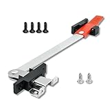
- Secure the RV EXIT Window: Replace the old egress window support with RV Murts emergency pop out window latch will providing extra peace of mind on-the-go. Aluminum steel bar has reliability for supporting your fully opened emergency window or lock it tightly for property protection.
- Safety First. Replace the old and cracking window bar with emergency window latch in time to avoid breaking the window when in emergency situation, keep your families safe, with a striking red handle helps you to quickly find the EXIT in the dark.
- Match the USA Standard: RV Murts EXIT window latch meets the need of everyday window support, with prominent steel fits for long time prop up job, plus, as a reliable window lock bar to secure the EXIT window tightly even the cold wind in winter can't enter, protecting your property.
- Two Design for Fitment: Offer 2 kinds of up side and down side window latch, the catch and keeper of egress window latch can spin 180 degrees to place on the left or right side and face up and down, designed 2 ways 4 screw holes to fit various EXIT windows, P7 shows size of each part, packaged with screws to ensure a secure fit.
- One Order for All: Keep your RV egress windows safe and secure with this reliable RV Exit window latch. Package included all the parts and accessories you need, please confirm the right kind latch you need, so can replace the old bar with RV egress window latch right away!

- Fit for: 2000-2006 Toyota Tundra.
- Replace Part Number: 62920-34012-B1. Please check it fit for your model.
- High-quality: Made of quality materials for reliable service, exact equivalent part meets the original manufacturer’s specifications and features.
- Easy Secure Installation: Plug and play, this product can be easily installed by yourself in minutes, no special skills required.
- Customer Service: All products are sold after strict inspection. We provide with professional consulting all the time. Contact with us if you have anything with question, we'll reply within 16 hours to offer help.

- Quality Material: The window tilt latch replacement is made of plastic, which is strong and not easy to break or deform.
- Window Parts: These tilt latch pairs are suitable for single or double hung vertical sliding windows.
- Elegant Design: The plastic construction spring-loaded latch pairs feature a classic white design that will complement your home decor.
- Easy to Use: Snap type sliding window tilt latch are easy to install and operate, saving time and effort.
- Window Latch Repair Kit: A total of 4 pieces of tilt window locks, including 2 left-hand locks and 2 right-hand locks, can replace old windows.

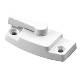
- Premium Window Latch Bracket for RV: Aucuda rv emergency window latch will help you keep your windows secure while on the road. Universal application for any size RV window, make sure your RV is safe and secure with the durable and reliable RV window latch bracket from Aucuda.
- Perfect Fit Every Time: Aucuda heavy-duty window secure bar holder is designed to be universally applied to any size RV window, ensuring a perfect fit every time. The perfect solution for keeping your windows secure no matter where you are.
- Excellent Durability: The RV egress window keeper has solid construction ensures long lasting strength and durability, provide protection against the elements, guard you and your families in years.
- Easy-to-Install: The simple design will make it easy to attach to any RV window frame, requiring minimal tools to mount it, only takes 1 minute to install, and you can enjoy peace of mind knowing that your RV is secured with Aucuda RV window latch bracket.
- Aucuda RV Window Latch Bracket: Package ONLY contains one set of latch bracket, the latch is NOT included. The durable and secure way to bring convenience and safety to your RV-living experience, thank you for choosing Aucuda EXIT window holder to guard your safety!

- Direct replacement - this sliding window latch is designed to match the fit and function of the original latch on specified vehicles.Material:Plastic
- Restores functionality - this latch is made to fit and fully restore part functionality after the original latch fails
- Durable construction - this part is made from quality materials to ensure reliable performance and long service life
- Trustworthy quality - backed by team of product experts in the United States and more than a century of automotive experience
- Ensure fit - to make sure this part fits your exact vehicle, input your make, model and trim level into the garage tool

- Fits 2003-17 Toyota Rear Window Latch: The rear window latch nut screw is used to repair or replace the Sienna rear window glass lock to ensure the stability and safety of the rear window glass, prevent rain, dust and wind noise from entering the car, and improve driving comfort and safety.
- Function: This rear window latch bolt nut screw cab glass is made of high-quality materials and workmanship, durable, rust-proof, anti-corrosion, and not easily deformed or damaged.
- Easy to install: It works perfectly with the original rear window glass lock, no additional tools or modifications are required, and the installation is simple and convenient.
- Packaging: Package contains 1x thumb screw and nut, 2 x rubber washers.
- Excellent Service: Thank you for purchasing our rear window latch nut screw. If you are not satisfied with our rear window screws or have questions, please feel free to contact us and we will give you the best solution immediately.

- QUANTITY & SIZE INFORMATION - The window locks security includes 2 pairs of tilt latches (4 pieces in total), consisting of both left and right-handed options. Before purchasing, please ensure to check the product size, which measures 3 x 1 inches, to confirmed a proper fit for your windows.
- DURABLE AND RELIABLE - Our spring-loaded window tilt latch is made of high-quality plastic, ensuring long-lasting performance without easily breaking or deforming. It is a reliable choice that will serve you well for years to come.
- EASY INSTALLATION - Installing our sliding window tilt latch is a breeze. It is lightweight, portable, You can quickly and effortlessly install it without the need for extensive time or effort.
- VERSATILE APPLICATION - Designed for single and double hung vertical sliding sash panels, our tilt latch allows for easy tilting inward and downward from the top, facilitating convenient cleaning and maintenance.
- PERFECTLY MATCHES YOUR DECOR - With its classic color, our sliding window tilt latch blends seamlessly with any home decoration style. It won't disrupt the overall aesthetics of your house, ensuring a harmonious and visually pleasing look.
- Designed for use with Silverline windows that have mounting holes 2-3/16 inch on center
- Used in vertical-sliding single- and double-hung windows in New Jersey and some other states
- Constructed of durable plastic and comes in a beautiful white finish, with all the necessary instructions and fasteners needed for installation
- Spring-loaded lever with cam-action locking allows you to lock your window securely (Keeper is sold separately)
- Please refer to the line art drawing for dimensions and compare with your original item before purchasing (Not Universal)
- Compatible with Toyota Tacoma 1989 1990 1991 1992 1993 1994 1995 1996 1997 1998 1999 Year
- Compatible with Toyota Pickup Hilux 89 90 91 92 93 94 95 96 97 Year
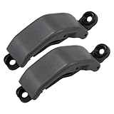
- RLB-HILON Rear Quarter Glass Window Latches at Gray Color
- Package Included: 1pair Rear Quarter Glass Window Latches, Installation Instruction is not included; Please make sure these window latches can fit for your car before placed the order.
- 3-MONTH WARRANTY: If for any reason at all, you are not fully satisfied with the window latches, you can rely on our service of free REPLACEMENT or REFUND
Last update on 2024-04-20 / Affiliate links / Images from Amazon Product Advertising API
This product presentation was made with AAWP plugin.
SEOCONTENT-START
OMB Control No.: 2127-0004 Part 573 Safety Recall Report 23E-018 The information contained in this report was submitted pursuant to 49 CFR §573 Manufacturer Name : AROW Global Corp Submission Date : MAR 07, 2023 NHTSA Recall No. : 23E-018 Manufacturer Recall No. : NR Manufacturer Information : Manufacturer Name : AROW Global Corp Address : 924 N Park View Circle Mosinee WI 54455 Company phone : 6936020 Population : Number of potentially involved : 1,500 Estimated percentage with defect : 100 % Equipment Information : Brand / Trade 1 : AROW Global Model : MV204 Part No. : MV2040000 Size : 40.83 x 40.10 Function : exit window Descriptive Information : The recalled product is based on the manufacturing date and the unique combination of size, glass type, window type, and customer. All part numbers with this combination have been identified and included. Approximately 1500 windows are affected and sold for use on New Flyer Industries transit busses between 2011 and 2023 Production Dates : MAR 03, 2011 – MAR 06, 2023 Brand / Trade 2 : AROW Global Model : MV204 Part No. : MV2040001 Size : 40.83 x 40.10 Function : NR Descriptive Information : * Production Dates : NOV 08, 2013 – MAR 06, 2023 Part 573 Safety Recall Report 23E-018 Page 2 The information contained in this report was submitted pursuant to 49 CFR §573 Brand / Trade 3 : AROW Global Model : MV204 Part No. : MV2040002 Size : 40.83 x 40.10 Function : NR Descriptive Information : * Production Dates : JAN 10, 2014 – MAR 06, 2023 Brand / Trade 4 : AROW Global Model : MV204 Part No. : MV2040005 Size : 40.83 x 40.10 Function : NR Descriptive Information : * Production Dates : FEB 25, 2014 – MAR 06, 2023 Brand / Trade 5 : AROW Global Model : MV204 Part No. : MV2040006 Size : 40.83 x 40.10 Function : NR Descriptive Information : * Production Dates : FEB 26, 2015 – MAR 06, 2023 Brand / Trade 6 : AROW Global Model : MV204 Part No. : MV2040007 Size : 40.83 x 40.10 Function : NR Descriptive Information : * Production Dates : JAN 24, 2017 – MAR 06, 2023 Part 573 Safety Recall Report 23E-018 Page 3 The information contained in this report was submitted pursuant to 49 CFR §573 Brand / Trade 7 : AROW Global Model : MV204 Part No. : MV2040008 Size : 40.83 x 40.10 Function : NR Descriptive Information : * Production Dates : AUG 04, 2017 – MAR 06, 2023 Brand / Trade 8 : AROW Global Model : MV204 Part No. : MV2040009 Size : 40.83 x 40.10 Function : NR Descriptive Information : * Production Dates : AUG 07, 2017 – MAR 06, 2023 Brand / Trade 9 : AROW Global Model : MV207 Part No. : MV2070049 Size : 49.31 x 42.60 Function : NR Descriptive Information : * Production Dates : FEB 14, 2013 – MAR 06, 2023 Brand / Trade 10 : AROW Global Model : MV207 Part No. : MV2070060 Size : 49.31 x 42.60 Function : NR Descriptive Information : * Production Dates : SEP 30, 2013 – MAR 06, 2023 Part 573 Safety Recall Report 23E-018 Page 4 The information contained in this report was submitted pursuant to 49 CFR §573 Brand / Trade 11 : AROW Global Model : MV207 Part No. : MV2070092 Size : 49.31 x 42.60 Function : NR Descriptive Information : * Production Dates : OCT 19, 2016 – MAR 06, 2023 Brand / Trade 12 : AROW Global Model : MV207 Part No. : MV2070101 Size : 49.31 x 42.60 Function : exit window Descriptive Information : * Production Dates : JUN 01, 2018 – MAR 06, 2023 Brand / Trade 13 : AROW Global Model : MV207 Part No. : MV2070108 Size : 49.31 x 42.60 Function : exit window Descriptive Information : * Production Dates : AUG 09, 2019 – MAR 06, 2023 Description of Noncompliance : Description of the Noncompliance : Specific emergency exit windows may not meet the passing criteria for FMVSS 571.217 S5.1. FMVSS 1 : 217 – Bus emergency exits and window retention and release FMVSS 2 : NR Description of the Safety Risk : Passenger retention during a vehicle accident may be reduced. Description of the Cause : Window latch mechanism failed prior to reaching any passing criteria during destructive testing. 75% of the force threshold was achieved at failure. Identification of Any Warning that can Occur : NR Involved Components : Part 573 Safety Recall Report 23E-018 Page 5 The information contained in this report was submitted pursuant to 49 CFR §573 Component Name : NR Component Description : NR Component Part Number : NR Supplier Identification : Component Manufacturer Name : AROW Global Corp Address : 924 North Park View Circle Mosinee Wisconsin 54455 Country : United States Chronology : NR Description of Remedy : Description of Remedy Program : A parts kit has been issued to correct the affected product. How Remedy Component Differs from Recalled Component : A black plastic latch component will be replaced with an aluminum component. Identify How/When Recall Condition was Corrected in Production : The recall condition has been corrected in production in March 2023. Recall Schedule : Description of Recall Schedule : New Flyer Industries has been notified and they are processing notifications to their vehicle owners Planned Dealer Notification Date : MAR 06, 2023 – MAR 31, 2023 Planned Owner Notification Date : MAR 06, 2023 – MAR 31, 2023 Purchaser Information : The following manufacturers purchased this defective/noncompliant equipment for possible use or installation in new motor vehicles or new items of motor vehicle equipment: Part 573 Safety Recall Report 23E-018 Page 6 The information contained in this report was submitted pursuant to 49 CFR §573 Name : New Flyer Industries Address : NR 00 Country : NR Company Phone : NR * NR – Not Reported
**************************************************************************************************************
OMB Control No.: 2127-0004 Part 573 Safety Recall Report 23E-018 The information contained in this report was submitted pursuant to 49 CFR §573 Manufacturer Name : AROW Global Corp Submission Date : MAR 17, 2023 NHTSA Recall No. : 23E-018 Manufacturer Recall No. : NR Manufacturer Information : Manufacturer Name : AROW Global Corp Address : 924 N Park View Circle Mosinee WI 54455 Company phone : 6936020 Population : Number of potentially involved : 1,500 Estimated percentage with defect : 100 % Equipment Information : Brand / Trade 1 : AROW Global Model : MV204 Part No. : MV2040000 Size : 40.83 x 40.10 Function : exit window Descriptive Information : The recalled product is based on the manufacturing date and the unique combination of size, glass type, window type, and customer. All part numbers with this combination have been identified and included. Approximately 1500 windows are affected and sold for use on New Flyer Industries transit busses between 2011 and 2023 Production Dates : MAR 03, 2011 – MAR 06, 2023 Brand / Trade 2 : AROW Global Model : MV204 Part No. : MV2040001 Size : 40.83 x 40.10 Function : NR Descriptive Information : * Production Dates : NOV 08, 2013 – MAR 06, 2023 Part 573 Safety Recall Report 23E-018 Page 2 The information contained in this report was submitted pursuant to 49 CFR §573 Brand / Trade 3 : AROW Global Model : MV204 Part No. : MV2040002 Size : 40.83 x 40.10 Function : NR Descriptive Information : * Production Dates : JAN 10, 2014 – MAR 06, 2023 Brand / Trade 4 : AROW Global Model : MV204 Part No. : MV2040005 Size : 40.83 x 40.10 Function : NR Descriptive Information : * Production Dates : FEB 25, 2014 – MAR 06, 2023 Brand / Trade 5 : AROW Global Model : MV204 Part No. : MV2040006 Size : 40.83 x 40.10 Function : NR Descriptive Information : * Production Dates : FEB 26, 2015 – MAR 06, 2023 Brand / Trade 6 : AROW Global Model : MV204 Part No. : MV2040007 Size : 40.83 x 40.10 Function : NR Descriptive Information : * Production Dates : JAN 24, 2017 – MAR 06, 2023 Part 573 Safety Recall Report 23E-018 Page 3 The information contained in this report was submitted pursuant to 49 CFR §573 Brand / Trade 7 : AROW Global Model : MV207 Part No. : MV2070108 Size : 49.31 x 42.60 Function : exit window Descriptive Information : * Production Dates : AUG 09, 2019 – MAR 06, 2023 Brand / Trade 8 : AROW Global Model : MV204 Part No. : MV2040009 Size : 40.83 x 40.10 Function : NR Descriptive Information : * Production Dates : AUG 07, 2017 – MAR 06, 2023 Brand / Trade 9 : AROW Global Model : MV207 Part No. : MV2070049 Size : 49.31 x 42.60 Function : NR Descriptive Information : * Production Dates : FEB 14, 2013 – MAR 06, 2023 Brand / Trade 10 : AROW Global Model : MV207 Part No. : MV2070060 Size : 49.31 x 42.60 Function : NR Descriptive Information : * Production Dates : SEP 30, 2013 – MAR 06, 2023 Part 573 Safety Recall Report 23E-018 Page 4 The information contained in this report was submitted pursuant to 49 CFR §573 Brand / Trade 11 : AROW Global Model : MV207 Part No. : MV2070092 Size : 49.31 x 42.60 Function : NR Descriptive Information : * Production Dates : OCT 19, 2016 – MAR 06, 2023 Brand / Trade 12 : AROW Global Model : MV207 Part No. : MV2070101 Size : 49.31 x 42.60 Function : exit window Descriptive Information : * Production Dates : JUN 01, 2018 – MAR 06, 2023 Brand / Trade 13 : AROW Global Model : MV204 Part No. : MV2040008 Size : 40.83 x 40.10 Function : NR Descriptive Information : * Production Dates : AUG 04, 2017 – MAR 06, 2023 Description of Noncompliance : Description of the Noncompliance : Specific emergency exit windows may not meet the passing criteria for FMVSS 571.217 S5.1. FMVSS 1 : 217 – Bus emergency exits and window retention and release FMVSS 2 : NR Description of the Safety Risk : During a crash the emergency exit window latch may fail and allow the window to open. Passenger retention during a vehicle crash may be reduced and present and increase risk of passenger injury. Description of the Cause : Window latch mechanism failed prior to reaching any passing criteria during destructive testing. 75% of the force threshold was achieved at failure. Identification of Any Warning that can Occur : NR Part 573 Safety Recall Report 23E-018 Page 5 The information contained in this report was submitted pursuant to 49 CFR §573 Involved Components : Component Name : NR Component Description : NR Component Part Number : NR Supplier Identification : Component Manufacturer Name : AROW Global Corp Address : 924 North Park View Circle Mosinee Wisconsin 54455 Country : United States Chronology : NR Description of Remedy : Description of Remedy Program : A parts kit has been issued to correct the affected product. The parts kit will be provided at no charge. Labor to install the parts kit will be provided by AROW Global or compensation for labor based on an agreed labor rate and time estimate. How Remedy Component Differs from Recalled Component : A black plastic latch component will be replaced with an aluminum component or a 2 latch assembly will be replaced with a 3 latch assembly. Identify How/When Recall Condition was Corrected in Production : The recall condition has been corrected in production in March 2023. Recall Schedule : Description of Recall Schedule : New Flyer Industries has been notified and they are processing notifications to their vehicle owners Planned Dealer Notification Date : MAR 06, 2023 – MAR 31, 2023 Planned Owner Notification Date : MAR 06, 2023 – MAR 31, 2023 Part 573 Safety Recall Report 23E-018 Page 6 The information contained in this report was submitted pursuant to 49 CFR §573 Purchaser Information : The following manufacturers purchased this defective/noncompliant equipment for possible use or installation in new motor vehicles or new items of motor vehicle equipment: Name : New Flyer Industries Address : NR 00 Country : NR Company Phone : NR * NR – Not Reported
**************************************************************************************************************
AROW Global Service Procedure Document Revision: 1 Procedure #: 2022-009 Page 1 of 17 Simplicity. Serviceability. Durability. 924 North Park View Circle | Mosinee, Wisconsin USA 54455 | P: 715.693.6020 | F: 715.693.7108 | www.arowglobal.com MATERIALS: MV204 Egress Upgrade 1 x AR0030053 MV204 Egress Upgrade Kit – RH TOOLS: 1 x Prop Bar (Optional, only needed if keeping window in bus) 1 x 5/32” Hex Wrench 1 x Flathead Screwdriver 1 x Blade Scraper 1 x Wire Cutter Pliers 1 x #2 Phillips Screwdriver 1 x Needle Nose Pliers 1 x #2 Phillips Drill Bit 1 x Drill Driver 1 x 760UV Sealant 1 x Isopropyl Alcohol 1 x Paper towel or cleaning rag 1 x 8” Caliper or longer 1 x Masking Tape Roll 1 x Clamp 1 x #30 Drill Bit 1 x Silicone Lubricant Spray Can 1 x Tack hammer or Ball Peen Hammer PROCEDURE: Note: It is recommended to remove the mainframe assembly and lay it glass down on a table or bench to allow for easier access to the egress system while performing the upgrade. This is not a necessity but will make removal and installation of the new egress system much more accessible. If the mainframe assembly will be kept in the window, skip steps “Removing the Mainframe Assembly from the Bus” and “Reinstalling the Mainframe Assembly into the Bus”. Instead, use the 3’ prop bar to hold the mainframe assembly open while performing the upgrade. Removing the Mainframe Assembly from the Bus 1. Pull the emergency release handle located on the jamb of the window and push open the mainframe assembly. See Figure 1. Figure 1: Egress handle circled in red. AROW Global Service Procedure Document Revision: 1 Procedure #: 2022-009 Page 2 of 17 Simplicity. Serviceability. Durability. 2. Open the mainframe assembly enough to allow access to the hinge retaining screws that are screwed into the female hinge on both sides of the window. These will be visible from the underside of the hinge. See Figures 2a and 2b. Figure 2a: Mainframe open to expose hinge retention screws. Figure 2b: Hinge retention screw circled in red. 3. Remove the hinge retaining screws using the 5/32” hex wrench. CAUTION: Once the hinge retaining screws have been removed, the male hinge on the mainframe assembly can be disengaged from the female hinge and allow the mainframe to be separated from the subframe if the mainframe assembly is opened a full 90 degrees from the closed position. 4. Remove the mainframe assembly from the subframe by rotating it outward to 90 degrees from resting position and slide it towards the bus body. Be sure to support the mainframe as its weight drops free from the subframe. See Figures 3a and 3b. Figure 3a: Mainframe open to 90 degrees. Figure 3b: Slide the mainframe assembly in the direction of the red arrow to separate it from the subframe. 5. Place the mainframe assembly on a clean flat surface with the glass down to allow optimal access to the egress system. NOTE: Laying a barrier down, such as cardboard, over the flat surface before placing the mainframe assembly on it can help prevent scratches from getting on the glass. 924 North Park View Circle | Mosinee, Wisconsin USA 54455 | P: 715.693.6020 | F: 715.693.7108 | www.arowglobal.com AROW Global Service Procedure Document Revision: 1 Procedure #: 2022-009 Page 3 of 17 Removing the Old Egress System Simplicity. Serviceability. Durability. 1. Begin removing the old egress system from the mainframe assembly by using the blade scraper to remove the sealant covering the split pins along the sill of the mainframe. See Figures 4a and 4b. Figure 4a: Blade scraper removing sealant. Figure 4b: Sealant removed. 2. Use the flathead screwdriver to pry out the locator blocks along the sill of the mainframe. See Figures 5a and 5b. Figure 5a: Flat head screwdriver wedged in the side of the locator block. Figure 5b: Locator block pried out of ER track. 924 North Park View Circle | Mosinee, Wisconsin USA 54455 | P: 715.693.6020 | F: 715.693.7108 | www.arowglobal.com AROW Global Service Procedure Document Revision: 1 Procedure #: 2022-009 Page 4 of 17 Simplicity. Serviceability. Durability. 3. Once the locator blocks are removed, use the wire cutter pliers to remove the split pins. Grip the side of the split pin that is closest to the glass with the wire cutter pliers. Be sure that the cutting side of the pliers is closest to the glass and contacting the mainframe as shown in Figures 6a and 6b. Figure 6a: Pliers gripping split pin. Figure 6b: Bottom of pliers contacting mainframe. 4. Squeeze the pliers tightly and rock the plier handle towards the glass to slide the split pin up a small amount as shown in Figures 7a and 7b. Figure 7a: Pliers rocked, sliding split pin up. Figure 7b: Split pin slid up. 5. Continue this process of sliding the split pin out until it can be gripped from the interior of the frame. Then reposition the pliers and repeat the same motions until the split pin is removed as shown in Figures 8a and 8b. Do this for all the split pins along the sill of the mainframe. Figure 8a: Split pin gripped from interior of frame. Figure 8b: Split pin slid up. 924 North Park View Circle | Mosinee, Wisconsin USA 54455 | P: 715.693.6020 | F: 715.693.7108 | www.arowglobal.com AROW Global Service Procedure Document Revision: 1 Procedure #: 2022-009 Page 5 of 17 Simplicity. Serviceability. Durability. 6. With the split pins removed, the ER bar can be disconnected from the ER handle. Slide the ER bar towards the egress handle a small amount to take pressure off the cable connecting the two together. See Figure 9. Figure 9: ER bar slid towards ER handle creating slack in ER cable. 7. Use the #2 Phillips screwdriver to remove the screw holding the ER cable to the ER bar. Make sure to keep holding the ER bar after the screw is removed to prevent the ER bar from flinging outwards. 8. With the screw removed, guide the ER bar out of the ER track of the mainframe and set it down as shown in Figure 10. Figure 10: ER bar removed from ER track. 924 North Park View Circle | Mosinee, Wisconsin USA 54455 | P: 715.693.6020 | F: 715.693.7108 | www.arowglobal.com AROW Global Service Procedure Document Revision: 1 Procedure #: 2022-009 Page 6 of 17 Simplicity. Serviceability. Durability. 9. Use the needle nose pliers to assist in removing the ER bar from the ER spring. It may be necessary to bend the hook of the spring outwards slightly to remove the ER bar. See Figures 11a and 11b. Figure 11a: Hold the ER bar and pull the spring hook with the pliers. Figure 11b: Pull the hook open with the pliers and slide the ER bar out. 10. Remove the ER handle from the mainframe using the #2 Phillips drill bit and the drill driver to remove the two screws holding it in place. See Figure 12. Figure 12: Removal of ER handle screws. 924 North Park View Circle | Mosinee, Wisconsin USA 54455 | P: 715.693.6020 | F: 715.693.7108 | www.arowglobal.com AROW Global Service Procedure Document Revision: 1 Procedure #: 2022-009 Page 7 of 17 Simplicity. Serviceability. Durability. 11. Once the screws are removed, slide the ER cable through the enlarged section of the slot cutout. See Figure 13. Figure 13: Use enlarged section of slot cutout to slide cable loops through. 12. Clean out any dirt and grime from the exposed egress track using isopropyl alcohol and either a rag or paper towel. Removal of the old egress system is now complete. Drilling Additional Split Pin Holes 1. Add two additional split pin holes to the mainframe to add support to the replacement ER bar. Figure 14 shows the horizontal dimensions that need to be marked on either side of the original split pin holes to drill the additional split pin holes. Figure 14: Dimensions for additional split pin holes. 924 North Park View Circle | Mosinee, Wisconsin USA 54455 | P: 715.693.6020 | F: 715.693.7108 | www.arowglobal.com AROW Global Service Procedure Document Revision: 1 Procedure #: 2022-009 Page 8 of 17 Simplicity. Serviceability. Durability. 2. Use the calipers to mark the horizontal locations for the additional split pin holes. Hook one jaw of the caliper on the edge of the original split pin hole and extend the caliper to the necessary dimension. Use the screw lock on the caliper to prevent the dimension from changing while scoring the new location. See Figures 15a and 15b. Figure 15a: Jaw hooked on original split pin hole. Figure 15b: Caliper extended to dimension for additional split pin. 924 North Park View Circle | Mosinee, Wisconsin USA 54455 | P: 715.693.6020 | F: 715.693.7108 | www.arowglobal.com AROW Global Service Procedure Document Revision: 1 Procedure #: 2022-009 Page 9 of 17 Simplicity. Serviceability. Durability. 3. Next, use the other jaw to score a small mark on the mainframe to mark where to align the drill jig for the next step. Repeat this for both sides using each sides respective dimension. See Figures 16a and 16b. Figure 16a: Jaw used to score frame. Figure 16b: Scored mark on the frame. 4. Once the locations for the additional split pin holes have been marked, use drill jig AR0030101 to drill the holes in the mainframe. Place the drill jig in the egress track and align it so that the center of the hole is lined up to the mark made in the previous step. 5. Once aligned, use the clamp to clamp the jig in place for drilling. Be sure that the clamp is positioned to apply clamping force to the portion of the jig that rests in the egress track and not to the top portion that extends above the mainframe. If not clamped in this manner, the jig will be tilted, and the hole will be drilled at an angle instead of perpendicular to the mainframe. See Figures 17a and 17b. Figure 17a: Drill jig clamped correctly. Figure 17b: Drill jig clamped incorrectly. 6. Apply a piece of masking tape to the #30 drill bit 1.5” from its tip to use as a depth indicator for drilling the additional split pin holes. See Figure 18. Figure 18: Drill bit taped for depth indication. 924 North Park View Circle | Mosinee, Wisconsin USA 54455 | P: 715.693.6020 | F: 715.693.7108 | www.arowglobal.com AROW Global Service Procedure Document Revision: 1 Procedure #: 2022-009 Page 10 of 17 Simplicity. Serviceability. Durability. 7. Use the taped #30 drill bit and the drill driver to drill the hole in the mainframe. Stop when the tape on the drill bit contacts the drill jig. See Figure 19. Figure 19: Additional split pin hole drilled to proper depth. 8. Repeat steps 4 through 7 for the second additional split pin hole. Be sure to reference Figure 14 and use the correct dimension for the split pin that is being drilled. 9. Clean out any metal shavings from the frame so that they don’t interfere with the operation of the new ER bar assembly. Once both additional holes are drilled and cleaned, the frame is ready for the new egress system to be installed. 924 North Park View Circle | Mosinee, Wisconsin USA 54455 | P: 715.693.6020 | F: 715.693.7108 | www.arowglobal.com AROW Global Service Procedure Document Revision: 1 Procedure #: 2022-009 Page 11 of 17 Installing the New Egress System Simplicity. Serviceability. Durability. 1. Spray the egress track along the sill of the window with silicone spray for lubrication. 2. Take the new egress handle AR0030047 and install the ER cable through the slot in the mainframe using the enlarged section of the slot to fit the looped ends through. See Figure 20. Figure 20: ER cable installed through slot. 3. Apply 760UV sealant to both mounting holes in the ER handle base and then run a bead of sealant between them. See Figure 21. Figure 21: Sealant applied to ER handle base. 4. Secure the ER handle to the mainframe using the drill driver and the #2 Phillips drill bit to install (2) 0001311F screws through the mainframe into the ER handle base. Clean up any squeezed-out sealant as necessary. See Figure 22. Figure 22: ER handle secured to frame. 924 North Park View Circle | Mosinee, Wisconsin USA 54455 | P: 715.693.6020 | F: 715.693.7108 | www.arowglobal.com AROW Global Service Procedure Document Revision: 1 Procedure #: 2022-009 Page 12 of 17 Simplicity. Serviceability. Durability. 5. With the ER handle installed, feed the ER cable down the side of the mainframe and through the locator block and split pin just below the handle. See Figures 23a and 23b. Figure 23a: Feed ER cable under locator block. Figure 23b: ER cable fed under locator block. 6. Take the new ER bar assembly AR0030050 and connect the jogged end to the ER return spring. Bend the hook of the ER return spring around the ER bar once installed. See Figures 24a and 24b. Figure 24a: Install spring hook into jogged end as shown. Figure 24b: Bend spring hook closed. 7. Place ER bar screw AR0003222 on the tip of the #2 Phillips screwdriver and install the treads through the loop end of the ER cable. Hold the screwdriver, screw, and cable with one hand, using an index finger to keep the screw on the end of the screwdriver as shown in Figure 25. Figure 25: Screw and ER cable held on screwdriver. 924 North Park View Circle | Mosinee, Wisconsin USA 54455 | P: 715.693.6020 | F: 715.693.7108 | www.arowglobal.com AROW Global Service Procedure Document Revision: 1 Procedure #: 2022-009 Page 13 of 17 Simplicity. Serviceability. Durability. 8. With the other hand, place the ER bar assembly into the ER track of the mainframe and slide it towards the ER handle with enough room to install the ER bar screw and hold it in place. See Figure 26. Figure 26: ER bar held in place with enough room to install ER handle cable. 9. Screw the ER bar screw into the ER bar assembly loose enough that the ER cable can move freely. See Figures 27a and 27b. Figure 27a: Installation of ER bar screw. Figure 27b: Screw partially installed with ER cable loose. 10. Release pressure on the ER bar assembly and let the ER return spring pull the slack out of the system. See Figure 28. Figure 28: ER cable without slack. 924 North Park View Circle | Mosinee, Wisconsin USA 54455 | P: 715.693.6020 | F: 715.693.7108 | www.arowglobal.com AROW Global Service Procedure Document Revision: 1 Procedure #: 2022-009 Page 14 of 17 11. Fully tighten the ER bar screw. Simplicity. Serviceability. Durability. 12. Function test the ER system by pulling the ER handle a few times to ensure the ER bar assembly freely slides forward and returns to its original position. 13. Install 2 of locator block AR0019292 into the ER track along the sill of the window between the ER latches of the ER bar. The locator blocks press into the channel but can be tapped in with a tack or ball peen hammer if necessary. See Figure 29. Figure 29: Locator blocks between ER latches. 14. Center each block on one of the split pin holes that are between the ER latches. If the ER latch is too close to the split pin hole to allow the locator block to be centered on the split pin hole, position the locator block with an 1/8” gap between it and the ER latch as shown in Figure 30. Figure 30: Offset locator block with gap between ER latch and block. 924 North Park View Circle | Mosinee, Wisconsin USA 54455 | P: 715.693.6020 | F: 715.693.7108 | www.arowglobal.com AROW Global Service Procedure Document Revision: 1 Procedure #: 2022-009 Page 15 of 17 Simplicity. Serviceability. Durability. 15. Install 1 of locator block AR0020076 into the ER track along the sill of the window between the ER return spring and the ER latch. See Figure 31. Figure 31: Locator block installed between ER return spring and ER latch. 16. Center the block on the split pin hole that was drilled in this location. If the ER latch is too close to the split pin hole to allow the locator block to be centered on the split pin hole, position the locator block with an 1/8” gap between it and the ER latch as shown in Figure 30 above. 17. With the locator blocks centered on their respective split pin holes, take the #30 drill bit and the drill driver and drill through the locator blocks using the split pin holes as guides. Do not drill the split pin holes in the frame any deeper than they already are, just drill through the locator blocks to allow the split pins to be installed. See Figures 32a and 32b. Figure 32a: Prior to drilling. Figure 32b: After drilling. 18. Blow out the plastic shavings once the locator blocks have been drilled out. Actuating the ER handle while blowing the shavings out can help clear all of the shavings out of the system. 924 North Park View Circle | Mosinee, Wisconsin USA 54455 | P: 715.693.6020 | F: 715.693.7108 | www.arowglobal.com AROW Global Service Procedure Document Revision: 1 Procedure #: 2022-009 Page 16 of 17 Simplicity. Serviceability. Durability. 19. Install 4 of split pin 0001110F into the split pin holes along the sill of the mainframe. Use the tack hammer or a ball peen hammer to tap them flush with the mainframe. See Figures 33a and 33b. NOTE: The split pin hole closest to the ER handle does not have a locator block installed centered on it. That split pin hole only gets a split pin installed into it. Figure 33a: Split pin prior to installation. Figure 33b: Split pin installed flush to mainframe. 20. Function test the ER system by pulling the ER handle a few times to ensure the ER bar assembly freely slides forward and returns to its original position. There may be a slight gritty feel as the ER handle passes beyond half of its actuation distance. This is acceptable and will not affect the ability of the egress system to function properly and within acceptable limits. 21. Clean the surface of the split pin and frame with alcohol then cover all the newly installed split pins with 760UV sealant and let sit for 1 hour before reinstalling into the bus. See Figure 34. Figure 34: Sealant applied to split pin. 924 North Park View Circle | Mosinee, Wisconsin USA 54455 | P: 715.693.6020 | F: 715.693.7108 | www.arowglobal.com AROW Global Service Procedure Document Revision: 1 Procedure #: 2022-009 Page 17 of 17 Simplicity. Serviceability. Durability. 924 North Park View Circle | Mosinee, Wisconsin USA 54455 | P: 715.693.6020 | F: 715.693.7108 | www.arowglobal.com 22. Once the 760UV sealant has cured for 1 hour, spray each newly installed locator block with silicone spray for lubrication as shown in Figure 35. The new egress system has now been fully installed and the mainframe assembly is ready to be reinstalled into the bus. Figure 35: Silicone spray lubricant applied to locator block. Reinstalling the Mainframe Assembly into the Bus 1. Reinstall the mainframe assembly into the bus by reversing the steps listed in section “Removing the Mainframe Assembly from the Bus” above. 2. Once the mainframe hinge is hooked, and the hinge retention screws have been reinstalled, visually inspect the alignment of the egress latches to the egress strikes to ensure that they are in alignment with each other. 3. Close the mainframe by pushing it open to a 45-degree angle and letting it drop closed on the subframe. If the window does not fully latch, open it to a greater angle and repeat until the mainframe fully latches on the subframe. The mainframe assembly is now reinstalled into the bus.
**************************************************************************************************************
AROW Global Service Procedure Document Revision: 0 Procedure #: 2023-001 Page 1 of 20 Simplicity. Serviceability. Durability. 924 North Park View Circle | Mosinee, Wisconsin USA 54455 | P: 715.693.6020 | F: 715.693.7108 | www.arowglobal.com MATERIALS: MV207 Egress Upgrade – 3 Latch 1 x AR0031337 MV207 Egress Upgrade Kit – LH 3 Latch TOOLS: 1 x Prop Bar (Optional, only needed if keeping window in bus) 1 x 5/32” Hex Wrench 1 x Flathead Screwdriver 1 x Blade Scraper 1 x Wire Cutter Pliers 1 x #2 Phillips Screwdriver 1 x Needle Nose Pliers 1 x Drill Driver 1 x 760UV Sealant 1 x Isopropyl Alcohol 1 x Paper towel or cleaning rag 1 x 6” Caliper 1 x Tape Measure 1 x Marking Pen 1 x Masking Tape Roll 1 x Clamp 1 x #30 Drill Bit 1 x 17/64” Drill Bit 1 x Silicone Lubricant Spray Can 1 x Tack hammer or Ball Peen Hammer 1 x 8-32 Rivet Nut Installation Tool 1 x Deburring Tool 1 x 3/32” Hex Wrench AROW Global Service Procedure Document Revision: 0 Procedure #: 2023-001 Page 2 of 20 PROCEDURE: Simplicity. Serviceability. Durability. Note: It is recommended to remove the mainframe assembly and lay it glass down on a table or bench to allow for easier access to the egress system while performing the upgrade. This is not a necessity but will make removal and installation of the new egress system much more accessible. If the mainframe assembly will be kept in the window, skip steps “Removing the Mainframe Assembly from the Bus” and “Reinstalling the Mainframe Assembly into the Bus”. Instead, use the prop bar to hold the mainframe assembly open while performing the upgrade. Removing the Mainframe Assembly from the Bus 1. Pull the emergency release handle located on the jamb of the window and push open the mainframe assembly. See Figure 1. Figure 1: Egress handle circled in red. 2. Open the mainframe assembly enough to allow access to the hinge retaining screws that are screwed into the female hinge on both sides of the window. These will be visible from the underside of the hinge. See Figures 2a and 2b. Figure 2a: Mainframe open to expose hinge retention screws. Figure 2b: Hinge retention screw circled in red. 924 North Park View Circle | Mosinee, Wisconsin USA 54455 | P: 715.693.6020 | F: 715.693.7108 | www.arowglobal.com AROW Global Service Procedure Document Revision: 0 Procedure #: 2023-001 Page 3 of 20 Simplicity. Serviceability. Durability. 3. Remove the hinge retaining screws using the 5/32” hex wrench. CAUTION: Once the hinge retaining screws have been removed, the male hinge on the mainframe assembly can be disengaged from the female hinge and allow the mainframe to be separated from the subframe if the mainframe assembly is opened a full 90 degrees from the closed position. 4. Remove the mainframe assembly from the subframe by rotating it outward to 90 degrees from resting position and slide it towards the bus body. Be sure to support the mainframe as its weight drops free from the subframe. See Figures 3a and 3b. Figure 3a: Mainframe open to 90 degrees. Figure 3b: Slide the mainframe assembly in the direction of the red arrow to separate it from the subframe. 5. Place the mainframe assembly on a clean flat surface with the glass down to allow optimal access to the egress system. NOTE: Laying a barrier down, such as cardboard, over the flat surface before placing the mainframe assembly on it can help prevent scratches from getting on the glass. 924 North Park View Circle | Mosinee, Wisconsin USA 54455 | P: 715.693.6020 | F: 715.693.7108 | www.arowglobal.com AROW Global Service Procedure Document Revision: 0 Procedure #: 2023-001 Page 4 of 20 Removing the Old Egress System Simplicity. Serviceability. Durability. 1. Begin removing the old egress system from the mainframe assembly by using the blade scraper to remove the sealant covering the split pins along the sill of the mainframe. See Figures 4a and 4b. Figure 4a: Blade scraper removing sealant. Figure 4b: Sealant removed. 2. Use the flathead screwdriver to pry out the locator blocks along the sill of the mainframe. See Figures 5a and 5b. Figure 5a: Flat head screwdriver wedged in the side of the locator block. Figure 5b: Locator block pried out of ER track. 924 North Park View Circle | Mosinee, Wisconsin USA 54455 | P: 715.693.6020 | F: 715.693.7108 | www.arowglobal.com AROW Global Service Procedure Document Revision: 0 Procedure #: 2023-001 Page 5 of 20 Simplicity. Serviceability. Durability. 3. Once the locator blocks are removed, use the wire cutter pliers to remove the split pins. Grip the side of the split pin that is closest to the glass with the wire cutter pliers. Be sure that the cutting side of the pliers is closest to the glass and contacting the mainframe as shown in Figures 6a and 6b. Figure 6a: Pliers gripping split pin. Figure 6b: Bottom of pliers contacting mainframe. 4. Squeeze the pliers tightly and rock the plier handle towards the glass to slide the split pin up a small amount as shown in Figures 7a and 7b. Figure 7a: Pliers rocked, sliding split pin up. Figure 7b: Split pin slid up. 5. Continue this process of sliding the split pin out until it can be gripped from the interior of the frame. Then reposition the pliers and repeat the same motions until the split pin is removed as shown in Figures 8a and 8b. Do this for all the split pins along the sill of the mainframe. Figure 8a: Split pin gripped from interior of frame. Figure 8b: Split pin slid up. 924 North Park View Circle | Mosinee, Wisconsin USA 54455 | P: 715.693.6020 | F: 715.693.7108 | www.arowglobal.com AROW Global Service Procedure Document Revision: 0 Procedure #: 2023-001 Page 6 of 20 Simplicity. Serviceability. Durability. 6. With the split pins removed, the ER bar can be disconnected from the ER handle. Slide the ER bar towards the egress handle a small amount to take pressure off the cable connecting the two together. See Figure 9. Figure 9: ER bar slid towards ER handle creating slack in ER cable. 7. Use the #2 Phillips screwdriver to remove the screw holding the ER cable to the ER bar. Make sure to keep holding the ER bar after the screw is removed to prevent the ER bar from flinging outwards. 8. With the screw removed, guide the ER bar out of the ER track of the mainframe and set it down as shown in Figure 10. Figure 10: ER bar removed from ER track. 924 North Park View Circle | Mosinee, Wisconsin USA 54455 | P: 715.693.6020 | F: 715.693.7108 | www.arowglobal.com AROW Global Service Procedure Document Revision: 0 Procedure #: 2023-001 Page 7 of 20 Simplicity. Serviceability. Durability. 9. Use the needle nose pliers to assist in removing the ER bar from the ER spring. It may be necessary to bend the hook of the spring outwards slightly to remove the ER bar. See Figures 11a and 11b. Figure 11a: Hold the ER bar and pull the spring hook with the pliers. Figure 11b: Pull the hook open with the pliers and slide the ER bar out. 10. Clean out any dirt and grime from the exposed egress track using isopropyl alcohol and either a rag or paper towel. Removal of the old egress system is now complete. Drilling Additional Split Pin Holes 1. Add two additional split pin holes to the mainframe to add support to the replacement ER bar. Figure 12 shows the horizontal dimensions that need to be marked on either side of the original split pin holes to drill the additional split pin holes. Figure 12: Dimensions for additional split pin holes. 924 North Park View Circle | Mosinee, Wisconsin USA 54455 | P: 715.693.6020 | F: 715.693.7108 | www.arowglobal.com AROW Global Service Procedure Document Revision: 0 Procedure #: 2023-001 Page 8 of 20 Simplicity. Serviceability. Durability. 2. Use the caliper to mark the horizontal locations for the additional split pin holes. Hook one jaw of the caliper on the edge of the original split pin hole and extend the caliper to the necessary dimension. Use the screw lock on the caliper to prevent the dimension from changing while scoring the new location. See Figures 13a and 13b. Figure 13a: Jaw hooked on original split pin hole. Figure 13b: Caliper extended to dimension for additional split pin. 924 North Park View Circle | Mosinee, Wisconsin USA 54455 | P: 715.693.6020 | F: 715.693.7108 | www.arowglobal.com AROW Global Service Procedure Document Revision: 0 Procedure #: 2023-001 Page 9 of 20 Simplicity. Serviceability. Durability. 3. Next, use the other jaw to score a small mark on the mainframe to mark where to align the drill jig for the next step. Repeat this for both sides using each sides respective dimension. See Figures 14a and 14b. Figure 14a: Jaw used to score frame. Figure 14b: Scored mark on the frame. 4. Once the locations for the additional split pin holes have been marked, use drill jig AR0030101 to drill the holes in the mainframe. Place the drill jig in the egress track and align it so that the center of the hole is lined up to the mark made in the previous step. 5. Once aligned, use the clamp to clamp the jig in place for drilling. Be sure that the clamp is positioned to apply clamping force to the portion of the jig that rests in the egress track and not to the top portion that extends above the mainframe. If not clamped in this manner, the jig will be tilted, and the hole will be drilled at an angle instead of perpendicular to the mainframe. See Figures 15a and 15b. Figure 15a: Drill jig clamped correctly. Figure 15b: Drill jig clamped incorrectly. 6. Apply a piece of masking tape to the #30 drill bit 1.5” from its tip to use as a depth indicator for drilling the additional split pin holes. See Figure 16. 924 North Park View Circle | Mosinee, Wisconsin USA 54455 | P: 715.693.6020 | F: 715.693.7108 | www.arowglobal.com AROW Global Service Procedure Document Revision: 0 Procedure #: 2023-001 Page 10 of 20 Simplicity. Serviceability. Durability. Figure 16: Drill bit taped for depth indication. 7. Use the taped #30 drill bit and the drill driver to drill the hole in the mainframe. Stop when the tape on the drill bit contacts the drill jig. See Figure 17. Figure 17: Additional split pin hole drilled to proper depth. 8. Repeat steps 4 through 7 for the second additional split pin hole. Be sure to reference Figure 12 and use the correct dimension for the split pin that is being drilled. 9. Clean out any metal shavings from the frame so that they don’t interfere with the operation of the new ER bar assembly. Once both additional holes are drilled and cleaned, the frame is ready for the new egress system to be installed. 924 North Park View Circle | Mosinee, Wisconsin USA 54455 | P: 715.693.6020 | F: 715.693.7108 | www.arowglobal.com AROW Global Service Procedure Document Revision: 0 Procedure #: 2023-001 Page 11 of 20 Installing the New ER Bar in the Mainframe Assembly Simplicity. Serviceability. Durability. 1. Spray the egress track along the sill of the window with silicone spray for lubrication. 2. Take the new ER bar assembly AR0030208 and connect the jogged end to the ER return spring. Bend the hook of the ER return spring around the ER bar once installed. See Figures 18a and 18b. Figure 18a: Install spring hook into jogged end as shown. Figure 18b: Bend spring hook closed. 3. Place ER bar screw AR0003222 on the tip of the #2 Phillips screwdriver and install the treads through the loop end of the ER cable. Hold the screwdriver, screw, and cable with one hand, using an index finger to keep the screw on the end of the screwdriver as shown in Figure 19. Figure 19: Screw and ER cable held on screwdriver. 4. With the other hand, place the ER bar assembly into the ER track of the mainframe and slide it towards the ER handle with enough room to install the ER bar screw and hold it in place. See Figure 20. Figure 20: ER bar held in place with enough room to install ER handle cable. 924 North Park View Circle | Mosinee, Wisconsin USA 54455 | P: 715.693.6020 | F: 715.693.7108 | www.arowglobal.com AROW Global Service Procedure Document Revision: 0 Procedure #: 2023-001 Page 12 of 20 Simplicity. Serviceability. Durability. 5. Screw the ER bar screw into the ER bar assembly loose enough that the ER cable can move freely. See Figures 21a and 21b. Figure 21a: Installation of ER bar screw. Figure 21b: Screw partially installed with ER cable loose. 6. Release pressure on the ER bar assembly and let the ER return spring pull the slack out of the system. See Figure 22. Figure 22: ER cable without slack. 7. Fully tighten the ER bar screw. 8. Function test the ER system by pulling the ER handle a few times to ensure the ER bar assembly freely slides forward and returns to its original position. 9. Install 4 of locator block AR0019292 into the ER track along the sill of the window between the ER latches of the ER bar. The locator blocks press into the channel but can be tapped in with a tack or ball peen hammer if necessary. See Figure 23. Figure 23: Locator blocks between ER latches. 924 North Park View Circle | Mosinee, Wisconsin USA 54455 | P: 715.693.6020 | F: 715.693.7108 | www.arowglobal.com AROW Global Service Procedure Document Revision: 0 Procedure #: 2023-001 Page 13 of 20 Simplicity. Serviceability. Durability. 10. Center each block on one of the split pin holes that are between the ER latches. If the ER latch is too close to the split pin hole to allow the locator block to be centered on the split pin hole, position the locator block with an 1/8” gap between it and the ER latch as shown in Figure 24. Figure 24: Offset locator block with gap between ER latch and block. 11. Actuate the ER bar once the locator blocks have been placed to ensure that they clear the latch bodies. 12. With the locator blocks centered on their respective split pin holes, take the #30 drill bit and the drill driver and drill through the locator blocks using the split pin holes as guides. Do not drill the split pin holes in the frame any deeper than they already are, just drill through the locator blocks to allow the split pins to be installed. See Figures 25a and 25b. Figure 25a: Prior to drilling. Figure 25b: After drilling. 13. Blow out the plastic shavings once the locator blocks have been drilled out. Actuating the ER handle while blowing the shavings out can help clear all of the shavings out of the system. 924 North Park View Circle | Mosinee, Wisconsin USA 54455 | P: 715.693.6020 | F: 715.693.7108 | www.arowglobal.com AROW Global Service Procedure Document Revision: 0 Procedure #: 2023-001 Page 14 of 20 Simplicity. Serviceability. Durability. 14. Install 4 of split pin 0001110F into the split pin holes along the sill of the mainframe. Use the tack hammer or a ball peen hammer to tap them flush with the mainframe. See Figures 26a and 26b. Figure 26a: Split pin prior to installation. Figure 26b: Split pin installed flush to mainframe. 15. Function test the ER system by pulling the ER handle a few times to ensure the ER bar assembly freely slides forward and returns to its original position. 16. Clean the surface of the split pin and frame with isopropyl alcohol then cover all the newly installed split pins with 760UV sealant and let sit for 1 hour before reinstalling into the bus or fully closing the window. See Figure 27. Figure 27: Sealant applied to split pin. 17. See Figure 28 for the complete updated ER bar in the mainframe assembly. Figure 28: Upgraded ER bar. 924 North Park View Circle | Mosinee, Wisconsin USA 54455 | P: 715.693.6020 | F: 715.693.7108 | www.arowglobal.com AROW Global Service Procedure Document Revision: 0 Procedure #: 2023-001 Page 15 of 20 Simplicity. Serviceability. Durability. 18. Once the 760UV sealant has cured for 1 hour, spray each newly installed locator block with silicone spray for lubrication as shown in Figure 29. The new ER bar has now been fully installed and the mainframe assembly is ready to be reinstalled into the bus. Figure 29: Silicone spray lubricant applied to locator block. Drilling the Additional ER Strike Plate Holes 1. With the mainframe assembly removed or propped open, face the window from the outside of the bus and use the tape measure to mark the location of the additional ER strike hole. Measure 12-1/4” from the inside edge of the right ER strike and use the marking pen to mark the location on the subframe. See Figures 30a and 30b. Figure 30a: Measuring off right strike. Figure 30b: Mark on subframe. 924 North Park View Circle | Mosinee, Wisconsin USA 54455 | P: 715.693.6020 | F: 715.693.7108 | www.arowglobal.com AROW Global Service Procedure Document Revision: 0 Procedure #: 2023-001 Page 16 of 20 Simplicity. Serviceability. Durability. 2. Once the location for the additional ER strike has been marked, use drill jig AR0031338 to drill the holes in the subframe. Tilt the drill jig to be under the inner subframe seal and rotate it to sit down on the sill of the subframe, making sure that the inner seal doesn’t interfere with the drill jig contacting the inner wall of the subframe extrusion. See Figures 31a and 31b. Figure 31a: Drill jig tipped under inner subframe seal. Figure 31b: Drill jig sitting on subframe sill. 3. Align the drill jig so that the mark that was made on the subframe in step 1 is centered in the right-side hole of the drill jig. See Figure 32. Figure 32: Right-side hole of drill jig aligned to mark on subframe. 4. Once aligned, use the clamp to clamp the jig in place for drilling. Verify that the drill jig is fully seated on the subframe surface before drilling. See Figures 33a and 33b. Figure 33a: Drill jig clamped in place. Figure 33b: Drill jig properly seated on the indicated edges. 924 North Park View Circle | Mosinee, Wisconsin USA 54455 | P: 715.693.6020 | F: 715.693.7108 | www.arowglobal.com AROW Global Service Procedure Document Revision: 0 Procedure #: 2023-001 Page 17 of 20 Simplicity. Serviceability. Durability. 5. Use the 17/64” drill bit and the drill driver to drill the ER strike holes in the subframe. Be sure that the drill jig doesn’t shift between hole drilling operations as that could cause the holes to be misaligned. See Figure 34. Figure 34: Drill aligned in drill jig. 6. Once the holes have been drilled, use the deburr tool to clean any burrs that were left from drilling so that the rivet nuts have a clean surface to mount to. See Figure 35. Figure 35: Deburr holes after drilling. 7. Once both additional holes are drilled and cleaned, the frame is ready for the additional ER strike plate to be installed. 924 North Park View Circle | Mosinee, Wisconsin USA 54455 | P: 715.693.6020 | F: 715.693.7108 | www.arowglobal.com AROW Global Service Procedure Document Revision: 0 Procedure #: 2023-001 Page 18 of 20 Simplicity. Serviceability. Durability. Installing the Additional ER Strike Plate in the Subframe Assembly 1. Use the rivet nut installation tool to install 1 of 0000870F into each of the new holes that were drilled in the subframe. See Figures 36a and 36b. Figure 36a: Rivet nut installation tool. Figure 36b: Rivet nuts properly installed. 2. With the rivet nuts installed, put a small bead of 760UV sealant around the rivet nut heads. Do NOT put any sealant into the rivet nuts. See Figure 37. Figure 37: Sealant applied around rivet nut heads. 3. Take the ER strike plate 0004040C and install the two AR0020115 screws into the mounting holes of the strike plate. See Figure 38. Figure 38: Screws installed in ER strike plate. 924 North Park View Circle | Mosinee, Wisconsin USA 54455 | P: 715.693.6020 | F: 715.693.7108 | www.arowglobal.com AROW Global Service Procedure Document Revision: 0 Procedure #: 2023-001 Page 19 of 20 Simplicity. Serviceability. Durability. 4. Align the ER strike plate and screws over the rivet nuts and drop the screws into the rivet nuts. Avoid getting any sealant on the screws as they drop in. See Figure 39. Figure 39: Install screws into rivet nuts. 5. Use the 3/32” hex wrench to tighten the screws into the rivet nuts. Be careful not to cross- thread the screws into the rivet nuts. NOTE: The screws have a Loctite patch applied to them that will prevent them from loosening. 6. Clean up any sealant that has squeezed out around the additional ER strike plate, especially along the interior edge where the ER plunger will latch and interface with the ER strike. 7. Use the blade scraper to remove a section of the outer subframe seal the width of the additional ER strike plate. It is ok if some adhesive residue is left behind once the seal is removed. The adhesive residue can be cleaned off using isopropyl alcohol if desired. See Figures 40a and 40b. Figure 40a: Blade scraper cutting seal. Figure 40b: Outer seal section fully removed. 8. The additional ER strike has now been fully installed. See Figure 41. Figure 41: Subframe sill with additional strike fully installed. 924 North Park View Circle | Mosinee, Wisconsin USA 54455 | P: 715.693.6020 | F: 715.693.7108 | www.arowglobal.com AROW Global Service Procedure Document Revision: 0 Procedure #: 2023-001 Page 20 of 20 Simplicity. Serviceability. Durability. 924 North Park View Circle | Mosinee, Wisconsin USA 54455 | P: 715.693.6020 | F: 715.693.7108 | www.arowglobal.com Reinstalling the Mainframe Assembly into the Bus 1. Reinstall the mainframe assembly into the bus by reversing the steps listed in section “Removing the Mainframe Assembly from the Bus” above. 2. Once the mainframe hinge is hooked, and the hinge retention screws have been reinstalled, visually inspect the alignment of the egress latches to the egress strikes to ensure that they are in alignment with each other. 3. Close the mainframe by pushing it open to a 45-degree angle and letting it drop closed on the subframe. If the window does not fully latch, open it to a greater angle and repeat until the mainframe fully latches on the subframe. The mainframe assembly is now reinstalled into the bus.
**************************************************************************************************************
924 North Park View Circle | Mosinee, Wisconsin USA 54455 | P: 715.693.6020 | F: 715.693.7108 | www.arowglobal.com Simplicity. Serviceability. Durability. ***IMPORTANT SAFETY RECALL*** NHTSA RECALL NO. 23E-018 AROW Global Corp. 924 Park View Circle Mosinee, WI 54455 March 17, 2023 Dear AROW OEM Customer, This notice is sent to you in accordance with the National Traffic and Motor Vehicle Safety Act. AROW Global Corp. has decided that certain window assemblies fail to conform to Federal Motor Vehicle Safety Standard No. 217 ”Window Retention”. Accordingly, AROW Global has submitted a Part 573 Non-Compliance Notification to the National Highway Traffic Safety Administration (NHTSA) on March 7,2023. Our records indicate that these windows have been supplied to New Flyer Industries for use in transit buses. The below table lists the affected window part numbers, AROW Global Corp. Part Number MV2040000 MV2040001 MV2040002 MV2040005 MV2040006 MV2040007 MV2040008 MV2040009 MV2070049 MV2070060 MV2070092 MV2070101 MV2070108 New Flyer Industries Part Number 437018 539483 547438 551155 583775 664220 690162 691327 507285 536821 640592 733775 808817 924 North Park View Circle | Mosinee, Wisconsin USA 54455 | P: 715.693.6020 | F: 715.693.7108 | www.arowglobal.com Simplicity. Serviceability. Durability. During compliance testing of the type of windows listed, the latching hardware became disengaged prior to any of the required criteria being met. During a vehicle crash, the emergency exit window latch may fail, allow the window to open, and fail to retain passengers within the vehicle, increasing the risk of injury. A rework solution has been developed and tested to ensure compliance to FMVSS 571.217 S5.1. AROW Global Corp. is making available these rework kits as of March 7, 2023. Included with the rework kit is an installation instruction. Rework kits will be provided at no charge and will take approximately 25 minutes to complete. Installation of rework kits will be provided by AROW Global service personnel or compensation for labor based on an agreed labor rate and time estimate. AROW Global Corp requests that New Flyer provides records of all vehicles with the affected windows. If AROW Global is unable to correct this noncompliance within a reasonable time, you may submit a written complaint to the; Administrator, National Highway Traffic Safety Administration, 1200 New Jersey Ave. SE, Washington, DC, 20590, Or call 1-888-327-4236 (TTY: 1-800-424-95130: Or go to htttp://www.safecar.gov Sincerely, Scot Fjeldsted VP Product Engineering
**************************************************************************************************************
OMB Control No.: 2127-0004 Part 573 Safety Recall Report 23E-018 The information contained in this report was submitted pursuant to 49 CFR §573 Manufacturer Name : Submission Date : AROW Global Corp MAR 27, 2023 NHTSA Recall No. : 23E-018 Manufacturer Recall No. : NR Manufacturer Information : Manufacturer Name : AROW Global Corp Address : 924 N Park View Circle Mosinee WI 54455 Company phone : 6936020 Population : Number of potentially involved : 1,500 Estimated percentage with defect : 100 % Equipment Information : Brand / Trade 1 : Model : AROW Global MV204 Part No. : MV2040000 Size : 40.83 x 40.10 Function : exit window Descriptive Information : The recalled product is based on the manufacturing date and the unique combination of size, glass type, window type, and customer. All part numbers with this combination have been identified and included. Approximately 1500 windows are affected and sold for use on New Flyer Industries transit busses between 2011 and 2023 Production Dates : MAR 03, 2011 – MAR 06, 2023 Brand / Trade 2 : Model : AROW Global MV204 Part No. : MV2040001 Size : 40.83 x 40.10 Function : NR Descriptive Information : * Production Dates : NOV 08, 2013 – MAR 06, 2023 Part 573 Safety Recall Report 23E-018 Page 2 Brand / Trade 3 : Model : AROW Global MV204 Part No. : MV2040002 Size : 40.83 x 40.10 Function : NR Descriptive Information : * Production Dates : JAN 10, 2014 – MAR 06, 2023 Brand / Trade 4 : Model : AROW Global MV204 Part No. : MV2040005 Size : 40.83 x 40.10 Function : NR Descriptive Information : * Production Dates : FEB 25, 2014 – MAR 06, 2023 Brand / Trade 5 : Model : AROW Global MV204 Part No. : MV2040006 Size : 40.83 x 40.10 Function : NR Descriptive Information : * Production Dates : FEB 26, 2015 – MAR 06, 2023 Brand / Trade 6 : Model : AROW Global MV204 Part No. : MV2040007 Size : 40.83 x 40.10 Function : NR Descriptive Information : * Production Dates : JAN 24, 2017 – MAR 06, 2023 The information contained in this report was submitted pursuant to 49 CFR §573 Part 573 Safety Recall Report 23E-018 Page 3 Brand / Trade 7 : Model : AROW Global MV204 Part No. : MV2040008 Size : 40.83 x 40.10 Function : NR Descriptive Information : * Production Dates : AUG 04, 2017 – MAR 06, 2023 Brand / Trade 8 : Model : AROW Global MV204 Part No. : MV2040009 Size : 40.83 x 40.10 Function : NR Descriptive Information : * Production Dates : AUG 07, 2017 – MAR 06, 2023 Brand / Trade 9 : Model : AROW Global MV207 Part No. : MV2070049 Size : 49.31 x 42.60 Function : NR Descriptive Information : * Production Dates : FEB 14, 2013 – MAR 06, 2023 Brand / Trade 10 : Model : AROW Global MV207 Part No. : MV2070060 Size : 49.31 x 42.60 Function : NR Descriptive Information : * Production Dates : SEP 30, 2013 – MAR 06, 2023 The information contained in this report was submitted pursuant to 49 CFR §573 Part 573 Safety Recall Report 23E-018 Page 4 Brand / Trade 11 : Model : AROW Global MV207 Part No. : MV2070092 Size : 49.31 x 42.60 Function : NR Descriptive Information : * Production Dates : OCT 19, 2016 – MAR 06, 2023 Brand / Trade 12 : Model : AROW Global MV207 Part No. : MV2070101 Size : 49.31 x 42.60 Function : exit window Descriptive Information : * Production Dates : JUN 01, 2018 – MAR 06, 2023 Brand / Trade 13 : Model : AROW Global MV207 Part No. : MV2070108 Size : 49.31 x 42.60 Function : exit window Descriptive Information : * Production Dates : AUG 09, 2019 – MAR 06, 2023 Description of Noncompliance : Description of the Noncompliance : Specific emergency exit windows may not meet the passing criteria for FMVSS 571.217 S5.1. FMVSS 1 : 217 – Bus emergency exits and window retention and release FMVSS 2 : NR Description of the Safety Risk : During a crash the emergency exit window latch may fail and allow the window to open. Passenger retention during a vehicle crash may be reduced and present and increase risk of passenger injury. Description of the Cause : Window latch mechanism failed prior to reaching any passing criteria during destructive testing. 75% of the force threshold was achieved at failure. Identification of Any Warning NR that can Occur : The information contained in this report was submitted pursuant to 49 CFR §573 Part 573 Safety Recall Report 23E-018 Page 5 Involved Components : Component Name : NR Component Description : MV ER HandleAssy Red-RH-13.25″ Component Part Number : 0371480A is replaced with AR0030047 Component Name : NR Component Description : MV Er Bar Assy RH – 2 Latch Component Part Number : 0003250A is replaced with AR0030050 Component Name : NR Component Description : Pin, Split-1/8 x 0.75″ Component Part Number : 0001110F quantity is increased by 2 Component Name : NR Component Description : MV Frame Locator Block-Flush Component Part Number : AR0020076 quantity is increased by 1 Component Name : NR Component Description : MV ER Bar Assy LH-3 Latch Component Part Number : AR0004371 is replaced with AR0030208 Component Name : NR Component Description : MV Flush Locator block Component Part Number : AR0019292 quantity is increased by 2 Component Name : NR Component Description : Screw, Hex BHCS, 8-32 x 0.374″ 18-8 SS Clear w/thread lock patch Component Part Number : AR0020115 quantity is increased by 2 The information contained in this report was submitted pursuant to 49 CFR §573 Part 573 Safety Recall Report 23E-018 Page 6 Component Name : NR Component Description : Nut, PemNut, 8-32, .08/.13 Component Part Number : 0000870F quantity is increased by 2 Component Name : NR Component Description : MV ER Strike Component Part Number : 0004040C quantity is increased by 1 Supplier Identification : Component Manufacturer Name : AROW Global Corp Address : 924 North Park View Circle Mosinee Wisconsin 54455 Country : United States Chronology : 2020- AROW discovered there were no test reports in our records verifying compliance to FMVSS 217 relating to four window types. 2020-two of the suspect non-compliant window types were tested and verified as being non-compliant, the remaining two window types were assumed to be non-compliant since they were similar 2020-2022-additional testing and analysis occurred to achieve compliance with FMVSS 217 2023 (March)-initiation of this recall along with the rework procedure and production of parts required for the rework. Description of Remedy : Description of Remedy Program : A parts kit has been issued to correct the affected product. The parts kit will be provided at no charge. Labor to install the parts kit will be provided by AROW Global or compensation for labor based on an agreed labor rate and time estimate. How Remedy Component Differs from Recalled Component : Identify How/When Recall Condition was Corrected in Production : A black plastic latch component will be replaced with an aluminum component or a 2 latch assembly will be replaced with a 3 latch assembly. The recall condition has been corrected in production in March 2023. The information contained in this report was submitted pursuant to 49 CFR §573 Part 573 Safety Recall Report 23E-018 Page 7 The information contained in this report was submitted pursuant to 49 CFR §573 Recall Schedule : Description of Recall Schedule : New Flyer Industries has been notified and they are processing notifications to their vehicle owners Planned Dealer Notification Date : MAR 06, 2023 – MAR 31, 2023 Planned Owner Notification Date : MAR 06, 2023 – MAR 31, 2023 Purchaser Information : The following manufacturers purchased this defective/noncompliant equipment for possible use or installation in new motor vehicles or new items of motor vehicle equipment: Name : New Flyer Industries Address : NR 00 Country : NR Company Phone : NR * NR – Not Reported
SEOCONTENT-END