
| “This site contains affiliate links for which OEMDTC may be compensated” |
January 30, 2018 NHTSA CAMPAIGN NUMBER: 18E007000
Vibrations Causing Damage to the Driveshaft
The vibration may cause driveshaft damage, disabling the vehicle and increasing the risk of a crash.
NHTSA Campaign Number: 18E007
Manufacturer Lippert Components, Inc.
Components POWER TRAIN, STRUCTURE
Potential Number of Units Affected 28
Summary
Lippert Components, Inc. (LCI) is recalling certain Ford F53 chassis reduced from a standard wheelbase of 208″ to 190″ for use by Forest River in Coachmen and Mirada recreational vehicles. The driveshaft may be misaligned, possibly resulting in excessive vibration at highway speeds.
Remedy
LCI will notify owners, and Forest River dealers will replace the two piece driveshaft with a three piece driveshaft, free of charge. The recall is expected to begin March 2018. Owners may contact LCI customer service at 1-574-538-4514. LCI’s number for this recall is 2018-001-59.
Notes
Owners may also contact the National Highway Traffic Safety Administration Vehicle Safety Hotline at 1-888-327-4236 (TTY 1-800-424-9153), or go to www.safercar.gov.
| M-TEC DRIVE SHAFT VIBRATION RECALL | |
| RECALL #18E-007 | LABOR FLAT RATE: 8 HOURS |
Purpose
This repair procedure describes how to address the drive shaft vibration on a motorized coach.
The individual components of the Forest River M-Tec Drive Shaft Recall Kit (720134) are listed in the kit parts list in the Resources Required section.
Labor Allowance
Eight man-hours per recall kit (two technicians at four hours each).
Safety
The “WARNING” symbol above is a sign that an installation procedure has a safety risk involved and may cause death, serious personal injury and severe product or property damage if not performed safely and within the parameters set forth in this manual. Always wear eye protection when performing this installation procedure. Other safety equipment to consider would be hearing protection, gloves, and possibly a full face shield, depending on the nature of the installation procedure.
The coach MUST be supported per manufacturer’s recommendations before working underneath. Failure to do so may result in death or serious personal injury.
The welding process can produce fumes, excessive heat, extreme light and sparks that can cause lung, eye and skin irritations and abrasions. Use appropriate personal protective equipment as necessary to prevent welding related injuries. Observe all state, local and industry welding standards.
Moving parts can pinch, crush or cut. Keep clear and use caution.
Resources Required
|
|
|
|
|
|
|
|
|
|
|
|
|
|
|
|
|
|
|
|
|
| Part # | Description | Qty |
| 720134 | Forest River M-Tec Drive Shaft Recall Kit | |
| 720135 | Tube, 2″ x 3″ (0.179 Nominal) cut to 33 5/8″ | 1 |
| 720142 | Tube, 2″ x 3″ (0.179 Nominal) cut to 33 7/16″ | 1 |
| 722046 | Tube, Spacer, 1 1/2″ x 2 x 2 5/8″ (0.179 Nominal) | 2 |
| 290453 | Plate, 9.0″ x 2.0″ x 1/4″ thick | 6 |
| 386062 | Plate, 9.0″ x 2.0″ x 3/16″ thick | 4 |
| 386064 | Plate, 9.0″ x 2.0″ x 11 Ga | 4 |
| 717868 | Drive Shaft Recall Kit | 1 |
| 719282 | Angle, 2.250″ x 5.938″ x 0.224″ x 9.375″ | 2 |
| 720136 | Plate, 1/2″ thick x 3″ x 9.5″ | 1 |
| 722211 | Bar, Flat, 1″ thick x 3″ x 9.5″ (as needed) | 1 |
| 251486 | Lock Nut, 1/2″ – 13, Grade 8 | 4 |
| 720137 | Flange Bolts, 1/2″ – 13 x 2″, Grade 8 | 4 |
| 720140 | M-Tec Drive Shaft Vibration Recall (CCD-0001198) | 1 |
Preparation
Check chassis for OEM cross-members. If there are two front cross-members, check to see if they are welded in-place. If OEM cross-members are welded, then modify cross-member in accordance with instructions in the Old Drive Shaft section. Old Drive Shaft
Removal of the old drive shaft, any welded-on OEM carrier bearing hangers and other modifications MUST be done before installing the new drive shaft. If the OEM bearing hanger is welded on, cut off and discard.
- Support old drive shaft with adjustable jack stands.
- Remove 12 mm, 12-point external wrenching bolts from transmission drive shaft end yoke (Fig. 1A).
- Discard bolts. Do NOT reuse.
- Remove 3/8″ – 24, 12-point external wrenching bolts (Fig. 2A) from differential drive shaft bearing straps (Fig. 2B).
- Discard bolts. Do NOT reuse.
- Remove bearing straps and set aside for later use.
- Remove old drive shaft.
- Cut off flange of exhaust hanger at front side of muffler, leaving a 1/32″ minimum gap.
- Remove manufacturer’s carrier bearing hanger. If welded on, cut off and discard.
- Clean top of chassis frame in front of roadside wheel-well to ensure an accurate digital protractor reading.
- Calculate transmission and pinion angles as follows:
A. With the digital protractor placed on top of the frame rail, zero-out the protractor.
B. Place digital protractor on top of chassis frame in front of roadside wheel-well.
C. Record calculation.
D. Press ABS/ZERO button (Fig. 3A) so the frame becomes the zero reference point.
Installation
NOTE: Blue lines indicate the centerline of an object or area. Enclosed green lines indicate a designated area, while non-enclosed green lines indicate a separator between designated areas.
Cross-Members
- Front cross-member is 33 5/8″.
A. Bevel the top corners to fit the radius inside the top of the frame rail.
I. Check for fit.
II. If cross-member is too long, trim each end to fit and to keep cross-member centered, if necessary.
B. With the cross-member clamped in-place, measure from inside driver’s side frame rail.
C. Make a mark at 13 1/2″.
D. Clamp a hanger bracket with the open end of the angle bracket facing towards the rear and with the driver’s side of the bracket lined up with the 13 1/2″ mark.
- Rear cross-member is 33 7/16″.
A. Place cross-member on bottom of inside frame rail.
I. Raise cross-member with supplied 1 1/2″ x 2″ x 2 5/8″ spacer tubes.
NOTE: Spacer tubes shall be positioned on the C-channel with a 2″ height.
II. If cross-member is too long, trim each end to fit and to keep cross-member centered, if necessary.
B. After fit, remove the cross-member.
C. Cut exhaust hanger bracket flange to allow clearance for the cross-member.
D. Place rear cross-member back inside frame rails on top of supplied 1 1/2″ x 2″ x 2 5/8″ spacer tubes as far to the rear as possible.
NOTE: Spacer tubes shall be positioned on the C-channel with a 2″ height.
E. On rear side of cross-member, measure from driver’s inside frame rail to driver’s side of 1/2″ x 3″ x 9 1/2″ plate 13 3/8″.
F. Weld on 1/2″ plate at 13 3/8″ location.
G. With the open end of the hanger bracket facing towards the rear, clamp hanger bracket from inside driver’s side frame rail to side of bracket 13 1/2″.
New Drive Shaft Assembly
- Assemble the supplied 3-piece drive shaft (Drive Shaft Recall Kit 717868), making sure the shaft alignment marks (Fig. 4) line up.
A. Support each drive shaft section with an adjustable jack.
C. Bolt front shaft to transmission with new 12 mm, 12-point bolts. Bolts NOT supplied.
C. Bolt rear shaft to pinion with new 3/8″ – 24, 12-point bolts. Bolts NOT supplied.
NOTE: Use previously remove bearing straps—Old Drive Shaft section, step 6.
D. Make sure the center support bearings line up with the hanger brackets.
E. Keep hanger brackets at 13 1/2″ from inside driver’s side frame rail.
- Set shaft angles and hanger brackets so there is enough room to shim shafts to make angle adjustments, if necessary.
- After all fit adjustments are made, weld all cross-members and brackets in-place.
Excessive heat and sparks generated during welding can ignite sensitive, flammable materials, which can result in serious personal injury or severe product and property damage. Remove or relocate welding-sensitive material. If only relocating, shield weld-sensitive materials. Wear appropriate personal protective equipment during the welding operation.
Taking Vertical Angle of Slope Readings
- After welds have cooled, use a hammer to tap the spacer tubes loose from the C-channel frame.
- Remove shielding from wire harnesses, brake lines, fuel lines and any other elements shielded during welding.
- Set wire harnesses, brake lines, fuel lines, and any other relocated elements, back to their normal locations.
- With the bottom of the digital protractor resting on a flat, horizontal surface, zero-out the digital protractor by pressing the ABS/ZERO button (Fig. 3A).
- Carefully place a short, vertical edge (Fig. 3) of the digital protractor across the flat surfaces of the transmission cover within the indicated area in figure 5.
A. The protractor’s reading will provide the slope angle of the transmission.
B. Record the reading in the Vertical Angle of Slope Chart.
Misaligned drive shafts can cause excessive vibration and wear that can result in damage to the transmission and differential. Make sure drive shaft alignment markings remain aligned to one another throughout assembly and installation to ensure proper drive shaft tolerances and operation.
- With the new drive shaft still held in-place, carefully set the digital protractor’s grooved flat bottom on top of the front shaft, taking care to make sure it is aligned with the centerline of the shaft (Fig. 6).
NOTE: If the digital protractor is not aligned properly on the drive shaft, a false reading may be given, resulting in misalignment of the entire drive shaft.
- Let digital protractor rest for at least six seconds before recording the reading.
- Record the slope angle of the front drive shaft (Front Shaft) in the Vertical Angle of Slope Chart.
- Repeat steps 6-8 for the middle and rear drive shafts (Middle Shaft, Rear Shaft).
NOTE: DO NOT zero-out the digital protractor between shaft readings. Shaft readings are relative to the transmission’s angle of slope (step 5).
Slope Adjustments
Referring to the Vertical Angle of Slope Chart, if any component’s measured slope is not within ±0.2 degrees of its required slope, adjustment is required.
| Vertical Angle of Slope Chart | ||
| Component | Required
Vertical Slope (Deg.) |
Measured
Vertical Slope (Deg.) |
| Transmission | 3.5 | |
| Front Shaft | 5.0 | |
| Middle Shaft | 3.6 | |
| Rear Shaft | 5.2 | |
| Axle | 3.6 | |
Incremental adjustments of component vertical slope angles to reach required limits may require operation of adjustable jacks to allow for the insertion of shims and the reuse of the digital protractor to verify the slope reading.
To adjust a measured slope, use a single or combination of shims to bring the slope in-line with the required limit, ±0.2 degree (Fig. 7).
Beginning with the front shaft, do as follows:
- Lower adjustable jack to create a gap between the bearing hanger and the carrier bearing.
- Place one or more shims into the gap.
- Raise adjustable jack until spacers are compressed.
- Set digital protractor on top of shaft and note the reading.
NOTE: DO NOT zero-out the digital protractor between shaft readings. Shaft readings are relative to the transmission’s angle of slope (Taking Vertical Angle of Slope Readings section, step 5).
A. Compare measured reading to required reading. Refer to Vertical Angle of Slope Chart.
B. If necessary, repeat shimming procedure until measured reading meets required reading within ±0.2 degree.
- After each required vertical slope angle has been met, insert 1/2″ – 13 UNC x 2″ hex flange bolts (Fig. 8A) through carrier bearing mounting holes and slots of shims and hangers.
- Secure bolts with 1/2″ – 13 UNC hex, all metal prevailing torque type, flange nuts (Fig. 8B).
- Use a 3/4″ wrench, 8″-10″ long, to tighten nuts.
- Repeat steps 1-7 for middle and rear shafts.
Post-installation
Remove all adjustable jacks from underneath the coach.
IMPORTANT SAFETY RECALL
NHTSA Safety Recall: 18E-007
Date: March XX, 2018
DEALER CUSTOMER NOTIFICATION
This Dealer Notification is sent to you in accordance with the requirements of the United States National Traffic and Motor Vehicle Safety Act.
REASON FOR THIS RECALL
Lippert Components, Inc. (“LCI”) has conducted a thorough investigation and decided that a defect which relates to motor vehicle safety exists in certain Forest River Coachmen MDA31FWF Mirada Motorhomes. There is the potential for excessive vibration under certain conditions when operating the unit at or above posted highway speeds which may affect the handling of the vehicle. Forest River records indicate your company purchased a 31FW which may have this issue. If the MDA31FWF listed on the attached VIN listing is still in your inventory, you must not sell the affected units. It is a violation of federal law to sell any of the units covered by this recall until the defect is remedied. The MTEC Drive Shaft Vibration Recall Instructions (Recall Repair Kit Part Number 720134) which directs you on how to complete the required remedy are enclosed with this letter.
WHAT WE WILL DO
LCI will provide a Recall Repair Kit to the repair location completing the remedy. LCI will reimburse labor charged to perform the remedy at the flat rate of 8.0 hours. The parts for the remedy are currently available.
WHAT YOU SHOULD DO
You must contact LCI’s Customer Service department at 574-538-4514 or via email at recall@lci1.com. LCI will coordinate with you shipment of the repair kit and payment of the labor charges.
If after contacting LCI’s Customer Service you are still not satisfied we have done our best to remedy this situation, you may also submit a written complaint to: Administrator, National Highway Traffic Safety Administration, 1200 New Jersey Avenue SE, Washington, DC 20590. You may call the toll-free Vehicle Safety Hotline at 1-888-327-4236 (TTY: 1-800-424-9153; or go to https://www.safercar.gov.) Federal regulations require that any vehicle lessor receiving this recall notice must forward a copy of this notice to the lessee within ten days.
We regret any inconvenience this action may cause you. As we are sure you will appreciate, the safety and quality of our products are of the utmost importance to us. Thank you for your attention and cooperation in this matter.
Sincerely,
Lippert Components, Inc.
1 Affected Product
Equipment
| BRAND | PART NO. | PRODUCTION DATES |
| LIPPERT | MODIFIED RV CHASSIS | 01/12/2017 – 04/19/2017 |
10 Associated Documents
Recall 573 Report- Amendment 1
RCLRPT-18E007-8498.PDF 215.416KB
 Loading...
Recall Quarterly Report #1, 2018-1
RCLQRT-18E007-6747.PDF 214.51KB
Loading...
Remedy Instructions and TSB
RCRIT-18E007-8379.pdf 17029.795KB
Loading...
Manufacturer Notices(to Dealers,etc)
RCMN-18E007-4675.pdf 246.003KB
Loading...
Recall Acknowledgement
Loading...
Defect Notice 573 Report
RCLRPT-18E007-9928.PDF 215.412KB
Loading...
Recall Quarterly Report #3, 2018-3
RCLQRT-18E007-1781.PDF 211.322KB
Loading...
Recall Quarterly Report #4, 2018-4
RCLQRT-18E007-5234.PDF 211.432KB
Loading...
Recall Quarterly Report #5, 2019-1
RCLQRT-18E007-3184.PDF 211.532KB
Loading...
Recall Quarterly Report #6, 2019-2
RCLQRT-18E007-1213.PDF 211.618KB
Loading...
Latest Recalls Documents
For the Latest and Most Recent Recalls Information Visit the link below…
https://www-odi.nhtsa.dot.gov/acms/cs/documentList.xhtml?docId=18E007&docType=RCL
| “This site contains affiliate links for which OEMDTC may be compensated” |
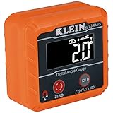
- VERSATILE DIGITAL ANGLE GAUGE AND LEVEL: Measure angles, check relative angles with zero calibration feature, or use as a digital level with ease
- HIGH VISIBILITY AND AUTO-ROTATING DISPLAY: Reverse contrast display improves visibility in low light conditions and automatically rotates when upside-down for easy viewing
- STRONG MAGNETIC BASE: Attach to ferromagnetic surfaces like pipe, electrical conduit, miter saw blades for woodworking, vents, ducts, and more for convenient hands-free operation
- V-GROOVE EDGES: Ensure optimal alignment on conduits and pipes for bending and alignment tasks
- WIDE MEASUREMENT RANGE: Measure between 0-90, or 0-180 degrees - useful when accounting for springback when bending conduit

- Precise Digital Angle Finder - Set blade bevel on table saws as well as tilt angles on your drill press, belt sanders and other power tools & machines!
- Easy Calibration - Press the ZERO button to calibrate the digital angle finder tool to any reference surface. Digital display angle ruler resolution is 0.1 degrees.
- Digital Angle Finder Magnetic - The magnetic angle finder base uses powerful rare earth magnets that strongly adhere to cast-iron tables and steel saw blades.
- Digital Inclinometer - The inclinometer on the Wixey WR300 digital angle gauge has a range of plus or minus 180 degrees making it versatile electronic level.
- Standard AAA Battery - New Wixey type 2 angle measuring tool uses one AAA battery for superior battery life and easy replacement so you can keep working.

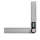
- 【2 in 1 Digital Angle Finder】TBVHOMM protractor has the function of a ruler and a protracting tool. The combination of a millimeter and inch scale ruler and a protractor makes it easy to measure internal and external angles. Suitable for woodworking, construction, drafting and other fields.
- 【2 Batteries Included】It comes with a CR2032 button battery inside, you can use it directly when you receive it. We also give you a additional battery as a spare.
- 【Large LCD Display & Accurate Reading】 TBVHOMM digital protractor is equipped with a large LCD display for easy reading; Measuring Range: 0~999.9°; Accuracy ±0.3°; Resolution 0.1°
- 【Lock, Zero, Hold and Reverse Angle Functions】This protractor can be locked at any angle by rotating the Locking Knob and pressing the HOLD function button will hold the reading. When you take large angle measurements and reverse measurements, long press the Rev button and the display can be read upside down. Zero button can reset the angle measuring tool at any time.
- 【Wide Application】Combining the functions of a digital angle meter and a protractor, it can be used to measure all the angles in your workshop for a wide range of uses, such as checking the angle of a table saw blade or the accuracy of a miter saw, making angle cuts or measurements, trimming or wall angle measurements. A perfect gift for woodworkers, architects, DIY enthusiasts, etc
- PATENTED MEASURING TECHNOLOGY -- Ruler and protractor combination for easy measuring inside and outside angles.
- DURABLE RULERS -- Well-made stainless steel rulers and laser etched measurements offer clear reading and years' usage.
- HIGH ACCURACY -- Accuracy of this protractor is ±0.3 degree. It is a good choice for most projects like woodworking, crown molding and daily use. Folded length: about 7.5 inch/220mm.Total length 400mm.
- LOCKING FUNCTION -- For read it easily, GemRed angle finder could be locked at any angle. *NO REVERSE ANGLE/DISPLAY FUNCTION.
- BATTERY -- CR2032 battery. Package contains battery.

- Manufactured from stainless steel, satin finished. 18 individual gages for easy use.
- Eight gaging surfaces per gage. Precision finished edges for accurate checking. Each gage checks primary, 1/2 primary and complementary angles
- Quick and accurate inspection of angles and I.D. or O.D. chamfers in or out of the machine. Positioning of lathe tools for chamfers
- Inspecting angles on the ground from tools and cutters. Fast set-ups and fixture of workpieces
- Eliminates time-consuming measuring set-ups. Indispensable for every inspector, tool maker, machiNist, layout and draftsman

- PROTRACTOR ARM: It's constructed of durable stainless steel and features a 6" adjustable arm for setting the bevel, transferring angles, and finding your measurement. It's an essential tool and gift idea for a fellow carpenter, student, or machinist.
- CONSTRUCTION PROTRACTORS: This square head protractor has a 0 to 180-degree semi-circle scale in forward and reverses directions to measure all angles on the job. The 3-3/8" x 2" head helps anchor the protractor against objects to hold it in place.
- ANGLE FINDER: Quickly and easily identify your angles with our rust-resistant measuring compass. The metal arm locks into place with a knurled thumb nut, allowing you to gauge the measurement of the inclination accurately.
- MEASUREMENT TOOLS: The project possibilities are endless when using our high-quality square-head protractor tool. You can master the art of building new cabinets, tables, chairs, wooden desks, framing, and various furniture makings.
- GENERAL TOOLS: We're a recognized leader in designing and developing specialized precision tools dedicated to delivering exceptional customer service. We encourage artisans and DIYers to work smarter, measure better, and repair more productively.

- ANGLE MEASURING TOOL: There's no more guesswork when it comes to measuring out your angles and cuts, thanks to our metal ruler. Create your layout on a flat surface, grab your slab of wood, your woodworking partner, and start the construction.
- SLIDING BEVEL: Set and transfer interior and exterior angles quickly and accurately with our level tool. We make it easy for you to build cabinetry, furniture, picture frames, and other wood-inspired projects.
- DIGITAL ANGLE GAUGE: Four large control buttons provide five functions, including power on/off, reading hold, read reverse angle, flip display, and clear readout. The automatic shut-off feature preserves battery life on our protractor tool.
- WOODWORKING RULER: This commercial-grade digital sliding T-bevel and digital protractor with an impact-resistant ABS handle features a 360-degree stainless steel blade. The battery-powered gauge includes 1 CR2032 lithium-ion battery.
- GENERAL TOOLS: We're a recognized leader in designing and developing specialized precision tools dedicated to delivering exceptional customer service. We encourage artisans and DIYers to work smarter, measure better, and repair more productively.
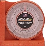
- ANGLE LOCATOR: Boasting excellent durability for unparalleled performance, this ergonomic locater level has a tough, high-impact molded body that promises to withstand the test of time.
- ACRYLIC LENS: This slope locator level features easy-to-read increments from 0-90 degrees printed on a durable acrylic lens
- POWERFUL MAGNET: The Johnson level features an extra strong, ceramic magnet that adheres to the ferrous metal surfaces, offering hand-free use.
- IDEAL APPLICATION: This level features V-groove edges that easily fit on pipe and conduit, making it an ideal and faster choice for plumbing tasks.
- PRODUCT SPECIFICATIONS: The Johnson Magnetic Angle Locator has sides marked with inches and metric graduations for convenience.

- GREAT REPEATABILITY - This angle gauge is designed with accuracy of ± 0.2° and the resolution is 0.1°. The measuring range: 0 to 360° (4*90°). Display unit: DEGREE only. It provides convenience in woodworking, construction, machinery, telecommunications, automobile etc. It is pre-calibrated in factory.
- STRONG ALUMINUM FRAMEWORK & MAGNETIC FLAT BASE - The digital angle gauge applied sturdy aluminum alloy instead of plastic for the main framework. It’ll provide years’ usage. 2 MEASUREING MODES - 1. Checking the true level. 2. Checking the relative angle between two surfaces.
- REVERSIBLE LCD DISPLAY - The Digital Angle Gauge has a large LCD display with backlight, which only needs one battery for providing accurate, quick and clear measurements and even you can easily read in dark environment. ERROR INDICATOR - If the digital angle gauge is used in an incorrect position (e.g. tilts diagonally over 30 degree), display will tell ERROR to make sure that use is getting the accurate measurement.
- EASY BATTERY INSTALLATION - You can install battery easily and need no screwdriver. WIth only one AAA battery, the digital angle gauge works 50 hours averagely. *Automatic shut-off after 5 minutes.
- WHAT YOU'LL GET - Digital angle gauge*1, 1.5V Alkaline battery*1, instruction*1

- ACCURATE - Crafted from CNC-machined Anodized Aluminum Alloy Steel. Features easy-to-read precision laser engraved scales.
- DESIGN - Internal Teflon O-ring mechanism swivels during operation and ensures smooth & precise read on inside/outside corners.
- FORGET ABOUT THE GUESSWORK - Two scales transfer your work angle directly to the miter saw for an accurate Miter cut, and Single cut.
- DO IT RIGHT THE FIRST TIME! - Perfect for crown molding, trim work, plumbing, and a variety of other carpentry applications.
- QUALITY - The 1/4-Inch thick aluminum alloy is stronger and won't bend like the plastic ones | Backed by our Lifetime Limited Warranty for your complete peace of mind!
Last update on 2024-03-23 / Affiliate links / Images from Amazon Product Advertising API
This product presentation was made with AAWP plugin.